
Abstract
On-machine error compensation (OMEC) is efficient at improving machining accuracy without increasing extra manufacturing cost, and involves the on-machine measurement (OMM) of machining accuracy and modification of program code based on the measurement results. As an excellent OMM technique, chromatic confocal sensing allows for the rapid development of accurate and reliable error compensation technique. The present study integrated a non-contact chromatic confocal probe into an ultra-precision machine for OMM and OMEC of machined components. First, the configuration and effectiveness of the OMM system were briefly described, and the relevant OMEC method was presented. With the OMM result, error compensation software was then developed to automatically generate a modified program code for error compensation. Finally, a series of cutting experiments were performed to verify the validity of the proposed OMEC method. The experimental results demonstrate that the proposed error compensation method is reliable and considerably improves the form error of machined components.
Introduction
In contrast to offline compensation, 1 on-machine error compensation (OMEC) has been proven to be a more effective method. 2 OMEC is conducted after the completion of the machining process without removing machined workpiece from machine tool. This could avoid the introduction of an additional systematic error caused by reinstalling the workpiece. Because of this advantage, OMEC has made significant results in terms of rapid compensation and high accuracy, and its application has received a great deal of attention.3–7 Jung et al. 8 used a touch-trigger probe system for on-machine measurement (OMM) in a three-axis vertical machining center. The original tool path was edited based on OMM result for the subsequent compensation machining process. Quinsat and Tournier 9 proposed an OMM method to obtain the surface profile of a machined component and introduced compensation approaches to reduce the influence of thermal expansion on the measurement results. Cho and colleagues10,11 used an OMM system in a milling machine to compensate for the machining error. Wang and colleagues12,13 developed a vision-based on-machine measurement and compensation method for volumetric errors of a micro machine tool. Jywe et al. 14 developed a three-dimensional dynamic performance measurement and error compensation method for a machine tool.
The literature review shows that a substantial amount of research has been focused on OMM and error compensation, and some methods have been successfully applied to compensate for the machining error of machine tools. However, relatively few investigations have been found on OMEC for a three-axis ultra-precision diamond turning machine. Thus, motivated by this deficiency, this article presents a theoretical and experimental study on OMEC for a three-axis diamond turning machine.
A non-contact chromatic confocal probe (CL1 MG140, STIL, France) is used to achieve the OMM of the machined component. Error compensation software is developed by using Microsoft Visual C++; 2010 programming package and modifies the program code based on the OMM result to perform error compensation. Error compensation is achieved by adding the corresponding compensation data into the previous program code to generate a new program code for the subsequent compensation processing. Finally, the validity of the proposed error compensation method was verified by the experimental method.
On-machine form error compensation
Configuration of the OMM system
The three-axis machine tool in the present study was a home-made T-type machine tool that mainly consisted of an aerostatic rotational axis denoted as a spindle or C-axis, and two hydrostatic translational slideways denoted as X- and Z-axes, respectively, as shown in Figure 1(a). In addition, the workpiece was affixed to the spindle via a vacuum chuck, and the spindle was positioned on the X-axis. The diamond tool and tool holder were installed on the Z-axis. An OMM system was integrated into a three-axis turning machine in our previous study, 15 and Figure 1 shows the OMM system. Two sufficiently accurate spheres, referred to as the master and reference spheres, respectively, were adopted. The center of the master sphere was required to be aligned with the spindle centerline by the inductance micrometer, and the reference sphere provided an orientation reference relative to the spindle. The reference sphere was connected to the spindle by a System 3R holder (GF Machining Solutions, Stockholm, Sweden), which is used to guarantee that the position of the reference sphere remained absolutely stable. A translation stage (Physik Instrumente, Karlsruhe, Germany) denoted as Y-axis was used to adjust the y-directional vertical position of the measurement probe. The validity of the OMM method was proved by comparing the results obtained by the OMM with those of Talysurf PGI 1240 (Taylor Hobson Ltd., Leicester, UK). The difference between the two measurement devices was extremely small. The small difference of these values suggests that the measurement accuracy of the OMM system was reliable. In addition, the dependence between these two measurement methods was further described by Pearson’s correlation coefficient. The results indicated that the two measurement methods were strongly correlated. 15
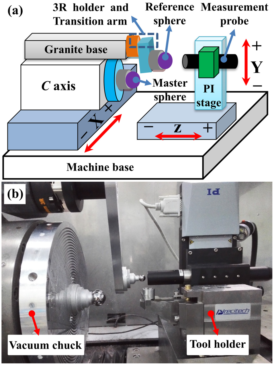
On-machine measurement (OMM) system in the present study: (a) sketch map of the OMM system; (b) layout of critical components from the OMM system.
Measurement procedure
Before the machining process, the OMM system was taken away from the machine tool for security purpose. After the machining process is complete, the workpiece was maintained on the spindle and then the removed components were reinstalled. The position of the reference sphere required recalibration after being reinstalled, which could ensure that the measurement probe conforms to the centerline of spindle during measurement. For the rotating symmetrical measured components, the two-dimensional sectional profile of the meridian was generally capable of representing the topography of measured component. The two-dimensional measurement was achieved by the x-directional movement of the workpiece relative to the measurement probe with a consistent linear velocity. The data acquisition card recorded the measured data with an equivalent time interval, and a curve representative of the sampling data was immediately plotted in the graphical interface.
Software development
Figure 2 shows a sketch map of the error compensation software based on the OMM result. The software contained four layers: input layer, data processing layer, output layer and graphical interface. The input layer included the objective surface and tool parameters. After importing the input information, the data processing layer is employed to establish the ideal profile of the objective surface and initial tool path, and simultaneously compared the ideal profile with OMM data to obtain the form error. Based on the data in the data processing layer, the output layer could generate the initial program code, compensation data and modified program code for compensation. After the data in the aforementioned three layers was transmitted into the graphical interface, the graphical interface plotted the corresponding curve for direct observation.
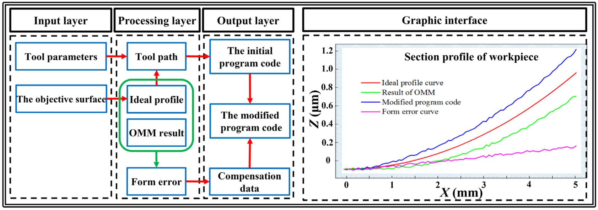
Schematic diagram of the software framework of the error compensation method.
Error compensation method
The flowchart for error compensation is shown in Figure 3(a). According to the requirement of the objective surface, the ideal profile data were first generated. Considering the tool’s radius and processing parameters, the initial program code was then obtained and used for the turning process. After the completion of the turning process, the OMM was performed for the machined component and the data processing module produced the measurement result of the OMM. The machined component was evaluated to be qualified or not according to the criterion that the form error of the machined component was less than the given tolerance range. If the form error was larger than the given tolerance, the deviation should be reduced as much as possible or even eliminated. Thus, error compensation data were requisite for a new modified program code for the compensation. A sketch of the data processing method for error compensation is shown in Figure 3(b). The deviation between the ideal profile data (red line) and measurement data (green line) is regarded as the form error (magenta line).
16
The ideal profile data

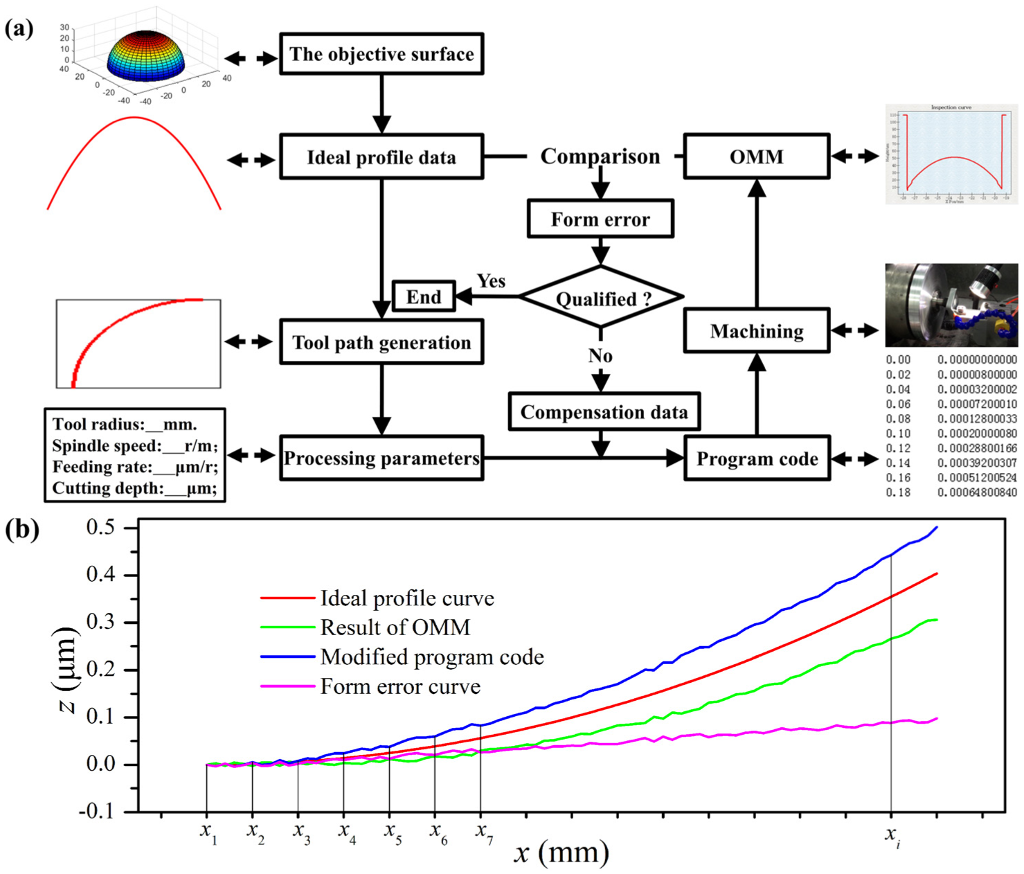
Illustration of the proposed error compensation method: (a) flowchart of the error compensation scheme; (b) sketch of the data processing method.
The compensation data should be in accordance with the form error. The form error curve was therefore discretized by a set of sectionalized lines with an equivalent interval into a set of sequential points, as shown in Figure 3(b), and these points were selected as the error compensation points. The number of compensation points should be equivalent to that of the sampling points of the OMM. The form errors at the compensation points (

and the compensated trajectory
Results and discussion
Two groups of experiments were designed to evaluate the validity of the proposed error compensation method. The first group was conducted on a workpiece for a flat surface of diameter 100 mm, and the second group was conducted on a workpiece for a convex spherical surface with a radius of curvature of 150 mm and workpiece diameter of 8 mm. The workpieces were machined under the same conditions by the home-made diamond turning machine.
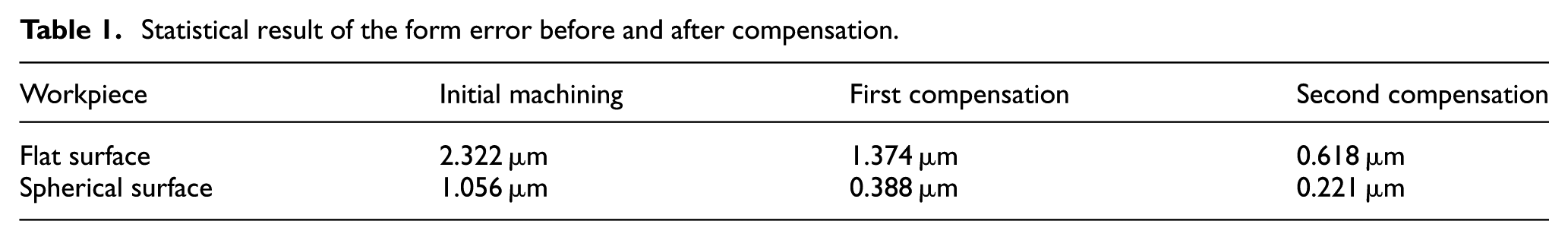
Table 1 shows the statistical results of the form error for the two workpieces before and after compensation. Figure 4 shows the measurement results and image of workpieces. Significant findings can be obtained from the experimental results. It can be observed that the form error was comparably improved by the application of the proposed error compensation method. For the flat surface, the OMM results indicate that the peak-to-valley (PV) value of the form error reduced from 2.322 μm to 0.618 μm after the second compensation. The accuracy improvement for the first and second compensations was approximately 40.83% and 73.39%, respectively, with respect to the initial machining. This demonstrates that the proposed error compensation method was effective for improving the machining accuracy. The comparison of the form error results for the spherical surface before and after compensation shows that the PV value of the form error dramatically decreased from 1.056 μm to 0.388 μm after the first compensation. The PV value decreased from 0.388 μm to 0.221 μm after the second compensation. The accuracy improvement for the first compensation was approximately 63.44% with respect to the initial machining and that for the second compensation was approximately 79.01%. Comparing the two experimental results, it is observed that although the spherical surface achieved a relatively greater improvement in performance on the dimensional scale than that for the flat surface, the accuracy improvement after the second compensation for both the flat surface and spherical surface was simultaneously greater than 70% with respect to the initial machining. It is reasonable to conclude that the proposed error compensation method based on the result of the OMM is effective and has the capacity to further improve the machining accuracy.
Statistical result of the form error before and after compensation.
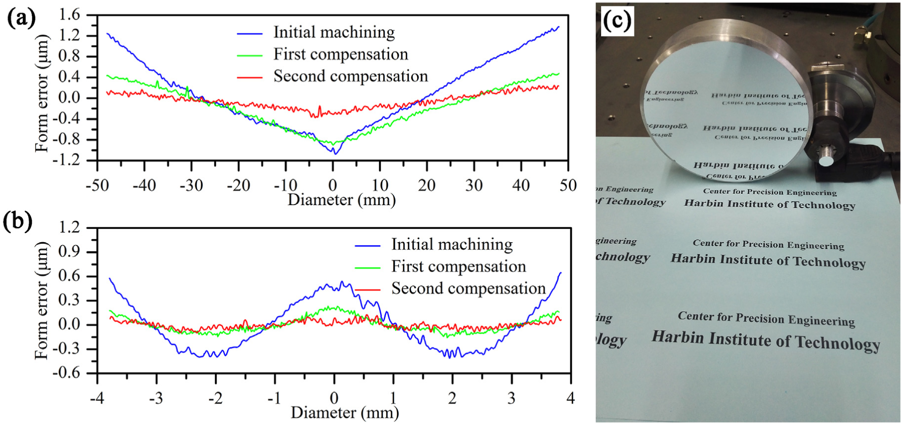
Measurement results for the workpiece before and after compensation: (a) result for the flat workpiece; (b) result for the spherical workpiece; (c) image of workpieces.
Conclusion
The OMEC method was proposed to compensate for the form error of a machined component in the ultra-precision machining. The experimental results validated the efficiency of the proposed error compensation method. Based on the obtained results, the following conclusions can be drawn:
The form error, which refers to the deviation between the ideal profile data and measurement data, was directly obtained by the OMM system. The presented error compensation method generated a new modified program code based on the OMM result for subsequent compensation processing. The experimental results demonstrated that the proposed error compensation method achieved over a 70% decrease of the PV value for both flat and spherical surfaces.
This proposed error compensation method can not only make it viable for integrating the turning process, OMM and OMEC techniques into an ultra-precision machine tool, but also greatly improve machining efficiency in ultra-precision manufacturing and simultaneously ensure machining accuracy.
Footnotes
Acknowledgements
Declaration of conflicting interests
The author(s) declared no potential conflicts of interest with respect to the research, authorship, and/or publication of this article.
Funding
The author(s) disclosed receipt of the following financial support for the research, authorship, and/or publication of this article: The present work was supported by the NSAF (National Safe Academic Foundation of National Natural Science Foundation of China, Grant No. U1530106) and National Natural Science Foundation of China (Grant No. 51005061).