
Abstract
Aspheric optics is widely used for many optical applications due to their advantages, that is, light weight, cost-effectiveness and efficiency. There are many fabrication challenges which affect the quality of aspheric optics used for infrared-based applications. Diamond turning is one of the most suitable techniques for fabrication of infrared aspheric lens with high profile accuracies, due to its deterministic approach. However, for optics with large sag value, multiple machining cycles are required to make the best fit surface. Repeated machining cycles result in generation of inherent stresses leading to subsurface deformation and poor quality. In this study, hybrid approach of grinding and machining is proposed for fabrication of silicon infrared optics in large volume. The proposed approach results in reduced fabrication time and subsurface deformation with improved surface quality and tool life. The profile accuracy after compensation of profile error (Pt) is 0.21 µm and surface roughness (Ra) 10.5 nm is achieved.
Introduction
Ultra-precision machining is widely used for the fabrication of advanced optical components, that is, aspheric, diffractive and freeform lenses, due to its accuracy and deterministic approach.1–3 Use of aspheric optics improves the performance of optical system by reducing the abrasions and system size. 4 Due to above advantages, aspheric lenses are preferred over conventional spherical lenses. Profile error correction of aspheric lens is a well-established area, and significant work is reported in the literature in last few decades.5–7 However, most of the studies are carried out for ductile materials, and relatively less research is reported for brittle materials. Due to complexities involved with the ultra-precision machining of brittle material (i.e. Si, Ge and SiC), it is still area of interest for researchers.8–10 Machining of brittle materials is difficult due to their material properties. Hence, ultra-precision machining is to be done in ductile regime to avoid generation of surface and subsurface cracks. Compensation process for any optics is iterative process and needs multiple processing cycles. Repeated machining in case of brittle materials leads to trapping of residual stresses beneath the machined surface, which is known as subsurface deformation.11–14 Similarly, excess lapping and grinding of optics can lead to surface damage and resist in achieving the required surface accuracies. To overcome this, systematic approach with optimised lapping parameters and gradually increasing lapping and grinding speed can be helpful to achieve the accuracies with less surface and subsurface damage.15–17 Rapid tool wear is another critical issue related to machining of brittle materials. Tool wear not only affects the profile accuracies but also increases the cost and processing time.18–21 Alternative approach to process the brittle material for development of aspheric lenses is grinding and polishing. 22 As grinding and polishing are the force-controlled processes and involvement of multiple cutting points makes them less deterministic. It is difficult to achieve the required profile accuracies in comparison to ultra-precision machining, due its more deterministic nature. Grinding and polishing processes are more prone to workpiece centring error, tool path errors and mounting errors, which limit the quality of fabricated optics.23–25 However, grinding alone is fast process to generate the initial profile due to higher material removal; moreover, it is cost-effective in comparison to ultra-precision machining due to use of costly diamond tools.
In this study, hybrid approach of grinding (for roughing) and ultra-precision machining (for corrective figuring) is proposed. Experiments are carried out to develop a silicon aspheric lens by proposed approach. Profile error compensation is done to achieve the higher profile accuracies. Proposed approach is compared with traditional approaches and found to be more accurate, fast and cost-effective.
Experimentation
Fabrication equipment and material
To achieve best fit spherical profile, single-crystal silicon sample is grinded on MCG 150 CNC machine. This machine has five-axes moment for pre- and fine grinding of spheres and aspheres as shown in Figure 1(a). Furthermore, single-point diamond turning (SPDT) of best fit spherical-shaped silicon was performed on an ultra-precision diamond turning machine (UPDTM) Nanoform 200 as shown in Figure 1(b). Diamond turning machine (DTM) has three axes with feedback resolution of 1.5 nm and is used to achieve the required radius of curvature (ROC) with minimum surface deformation and high surface quality. Parameters used for the rough and finished cut using DTM are given in Table 1.
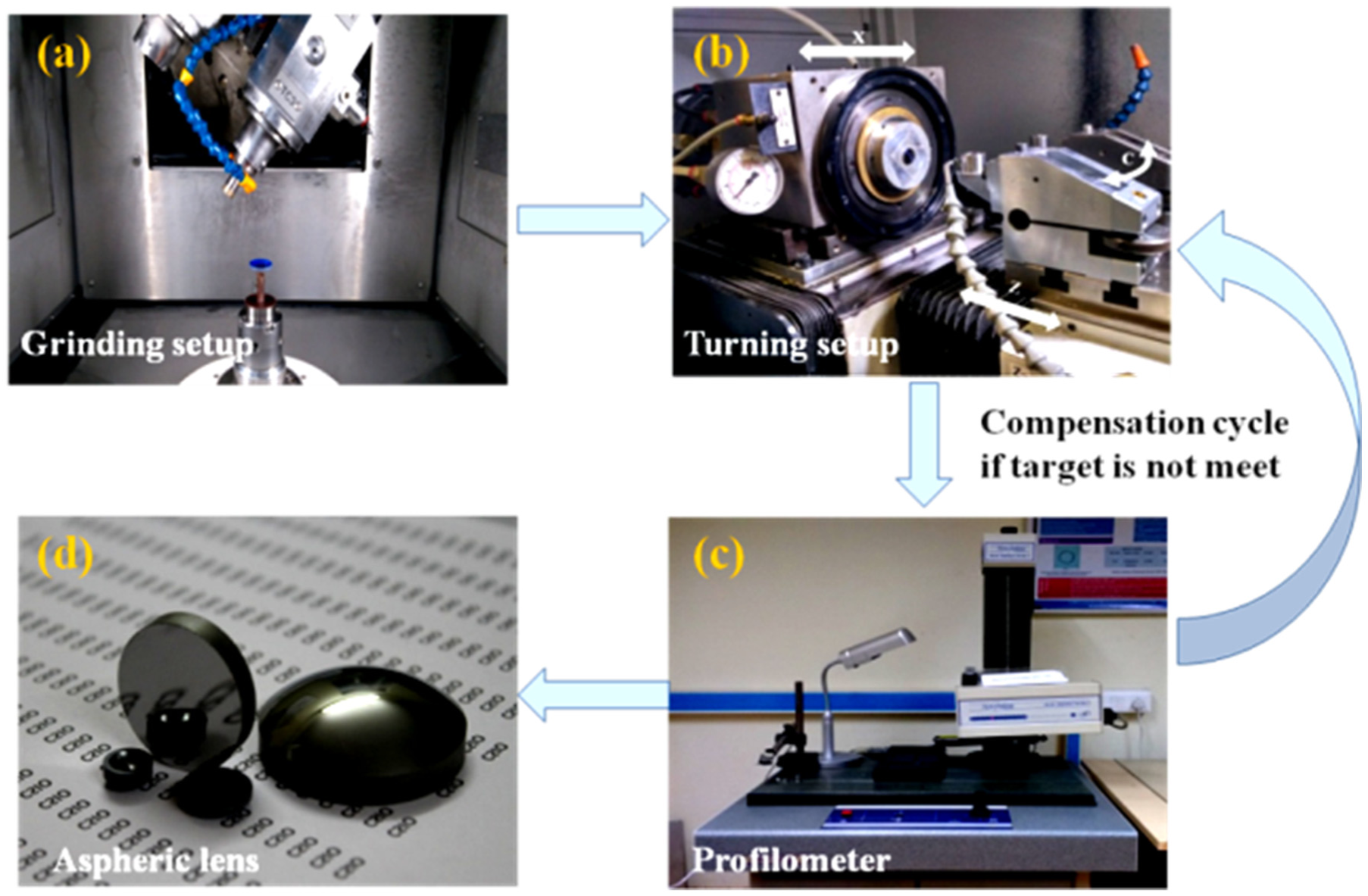
Schematic of the fabrication and compensation process: (a) grinding setup, (b) diamond turning setup, (c) profilometer PGI-120, and (d) finished aspheric lens.
Parameters used for aspheric generation during diamond turning.
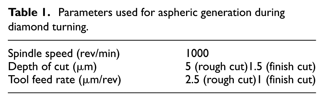
A monocrystalline diamond tool having a nose radius, rake angle and clearance angle of 0.750 mm, –20° and 10°, respectively, is used for the fabrication of aspheric surface.
Profile error measurement
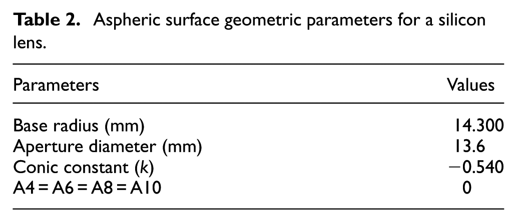
Profile error can come into existence in the workpiece due to stresses induced in the surface due to processing of the material, wear in tool, improper tool setting and offset in the tool, workpiece and spindle. After turning, profile error is measured by PGI-120 (Taylor Hobson-made). Measurement parameters considered are Pt (highest peak to lowest valley), Ra (surface roughness) and ROC, as shown in Table 2. After the turning, surface roughness and profile are checked on the contact-type profilometer having the stylus tip radius of 2 μm. The vertical measurement range and resolution are 10 mm and 16 nm, respectively.
Aspheric surface geometric parameters for a silicon lens.
Existing approach
Since the last decade, ultra-precision machining is preferred for the fabrication of aspheric lens. To get the high profile accuracies and good surface finish, this technique is preferred. But there are some complexities present in this process. As this process is highly complex and higher degree of precision is required to align the tool and workpiece. So, for the machining of brittle material, tool wear is also a big issue which needs to be solved. If we generate a silicon lens from a blank itself, then tool wear is the problem which makes this process more expensive. So, we need two different tools for the fabrication: one for roughing and another for finishing. As after the number of cycles, the tool wear will come into existence.
As in earlier approach, first we need to roughly remove the material from the blank. For the sag of 2 mm, we need approximately 200 cycles with the feed, depth of cut and spindle speed of 10 µm/rev, 10 µm and 1000 rev/min, respectively. In our other study, we found that with depth of cut more than 10 µm brittle material is more prone to subsurface deformation, which degrades the optical quality and output. 26 Many researchers found that with more number of repeated cycles more stresses are being developed. Thus, with the increased number of cycles, more stresses will be generated and will be stored in the component leading to subsurface deformation in the component. So, we need to reduce the number of cycles on the component. This approach will be helpful in saving the diamond tool, cost of the process and improve the output of component.
Hybrid approach
In hybrid approach, an attempt has been made to save the diamond tool used in ultra-precision machining and time for the fabrication of aspheric silicon lens. Two different processes were used for the fabrication of this lens, that is, grinding and turning. For the rough removal of material, grinding process is used. The aspheric compensation with grinding and turning is carried out in the OptoTech grinding machine and Precitech Nanoform 200. The equation of aspheric surface is expressed as
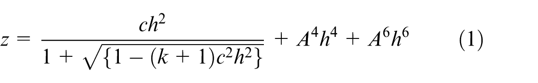
where k is the conic constant, z is the sag, h is the aperture and c is curvature (1/R = c, where R is ROC).
The hybrid approach is shown in Figure 2. In this approach, initially grinding of silicon is done in two steps (rough grinding and fine grinding). The aim of grinding is to remove the volume of material and get the spherical (i.e. best fit); after this, the lens is measured and required tool path for aspheric is generated by DIFFSYS, and accordingly, the turning is performed. After turning. Si lens is characterised by phase grating interferometer (PGI), and accordingly, the tool path is given to the machine. The tool path generated for the compensation is point to point. Then, the compensation surface is analysed for the required target. If the required target is achieved, then we stop the process; otherwise, we again give the iteration till we get the required profile.
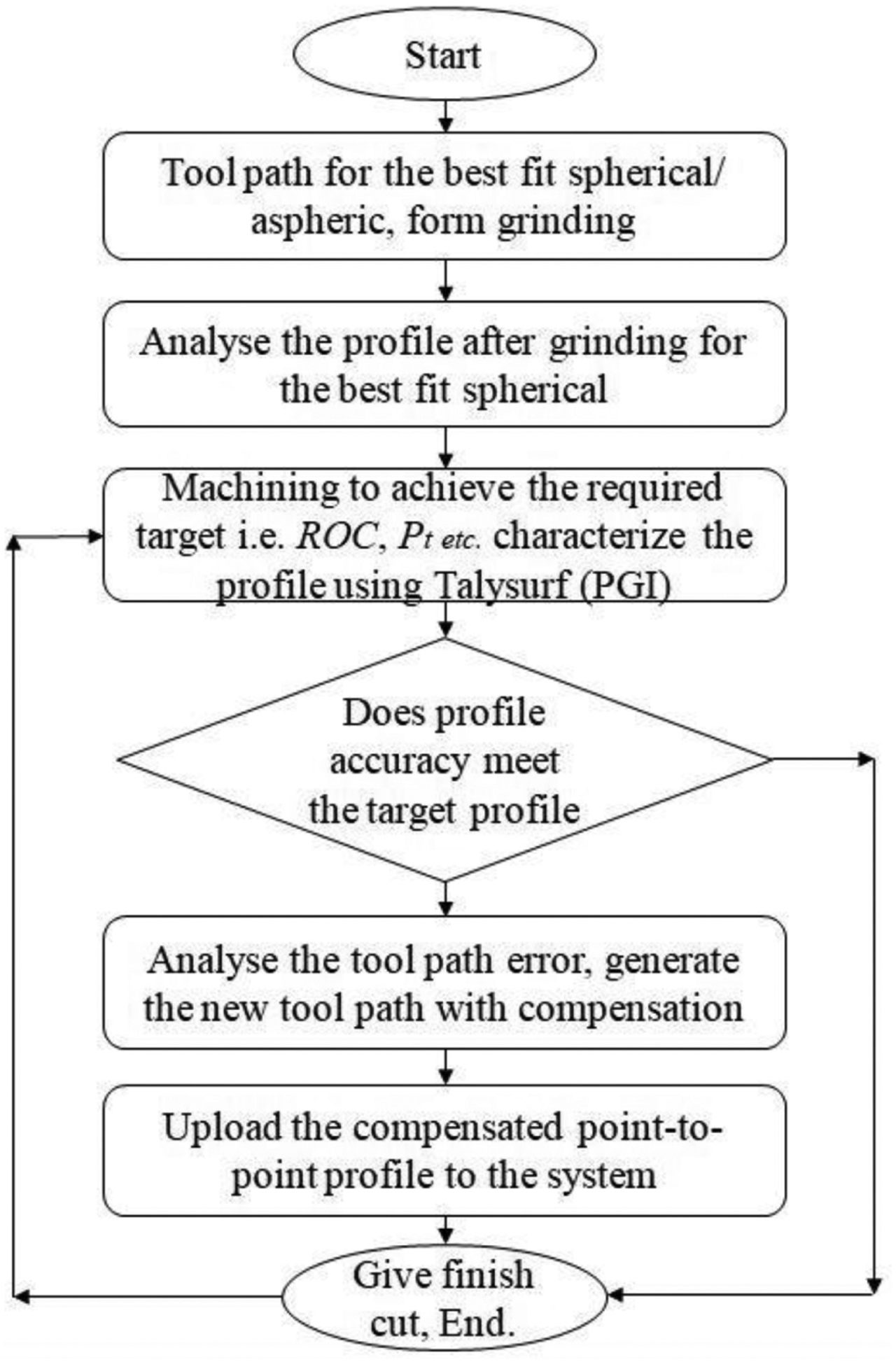
Flowchart of advanced approach for aspheric compensation.
Compensation process and results
This study focuses on the hybrid approach for the fabrication of aspheric lens with less tool wear and low cost. Initial study on silicon was done from where the machining parameters are chosen. 27
In the grinding and turning experiments, a silicon convex aspheric surface is fabricated. The protocol and procedure are shown in Figure 2. Geometric parameters are given in Table 2.
Initially, the best fit sphere of radius 14.78 mm is generated from the CNC grinding OptoTech-made. For the rough grinding, D64 grain size tool is used with feed rate of 0.1 mm/min, and for fine grinding, D20 grain size is used with feed rate of 0.05 mm/min and spindle speed of 3560 r/min. After initial grinding, diamond turning machining was done to obtain the final profiles using Nanoform 200, and the compensation is done by repeated cut. Then, re-compensation was done to achieve the required accuracies. These measurements are done by contact-type profiler.
Initially, tool and workpiece are aligned with the rotational axis of the spindle in the range of 2 µm. After the first cut, roughness is 55.2 nm, Pt is 1.4536 µm and ROC achieved is 14.2500 mm as shown in Figures 3(a) and 4(a). As after first cut, it can be seen that there is a variation in ROC of about 0.05 mm and Pt > 1. The point-to-point compensated path is then imported to the machine and again cut was initiated. Then, after second cut and first compensation, surface roughness was improved to 16.9 nm with Pt of 0.5371 µm, and ROC reduces to 14.2780 mm, which is shown in Figures 3(b) and 4(b). Then, again practising the same procedure as shown in flowchart (Figure 2) giving the third cut and second compensation, the required best conditions are meet. ROC achieved is 14.306 mm with Ra of 10.5 nm and Pt of 0.211 µm shown in Figures 3(c) and 4(c), which is considered of high quality in case of infrared (IR) optics.
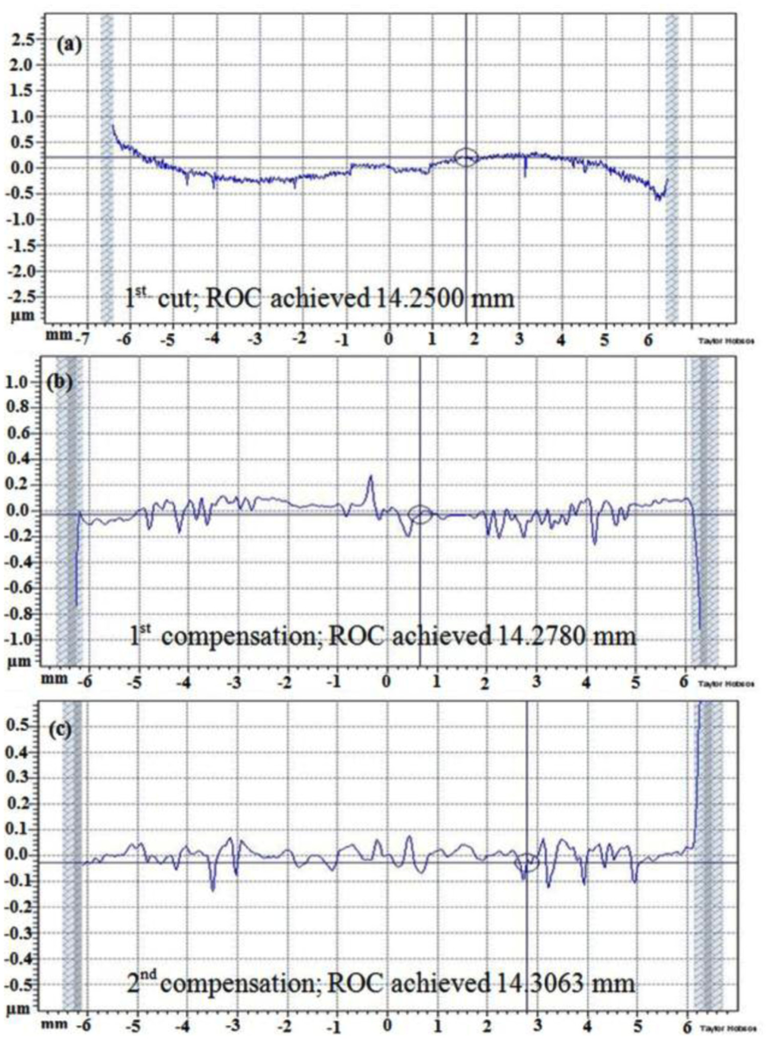
Profile error compensation results: (a) first cut Pt of 1.4536 µm and ROC of 14.2500 mm, (b) first compensation Pt of 0.5371 µm and ROC of 14.2780 mm and (c) second compensation Pt of 0.211 µm and ROC of 14.3063 mm.
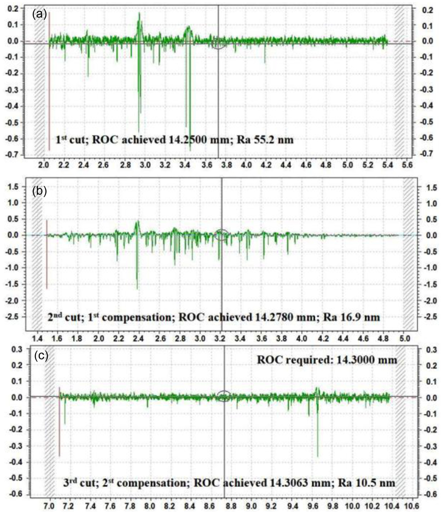
Surface roughness profile obtained at (a) first cut Ra is 55.2 nm, (b) first compensation Ra is 16.9 nm and (c) second compensation Ra is 10.5 nm.
It was found that as we give more number of cycles, more stresses are being developed due to penetration of tool into workpiece. Thus, with the increased number of cycles, more stresses will be generated and will be stored in the component leading to subsurface damage. But during this compensation process, no significant tool wear was observed. This can be seen in Figure 5. As the contact cycle time between the tool and workpiece is very less, less number of stresses will be stored in the tool and workpiece, leading to improved life of tool and good surface quality of workpiece.
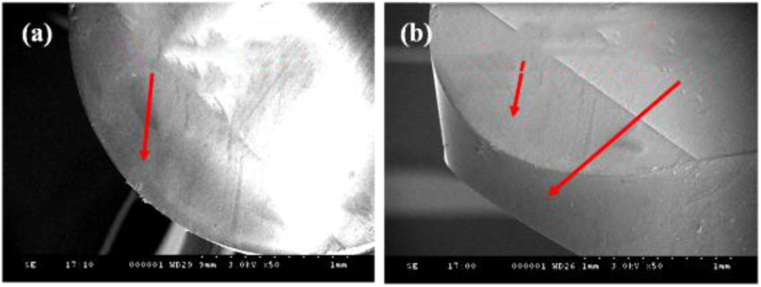
SEM image of the diamond tool showing no significant tool wear on the rake face and flank face after compensation cycles at 50× magnification and voltage of 3.0 kV: (a) top view showing rake face and (b) side view showing rake face and flank face.
Then, to check the accuracy of the hybrid process, comparison of the profile error during polishing and turning is done. During polishing compensation of aspheric lens, it was found difficult to control the profile error. But, in case of ultra-precision turning, the required profile is achieved in less number of cycles with higher accuracy. Figure 6 shows the comparison of profile error during both the processes.
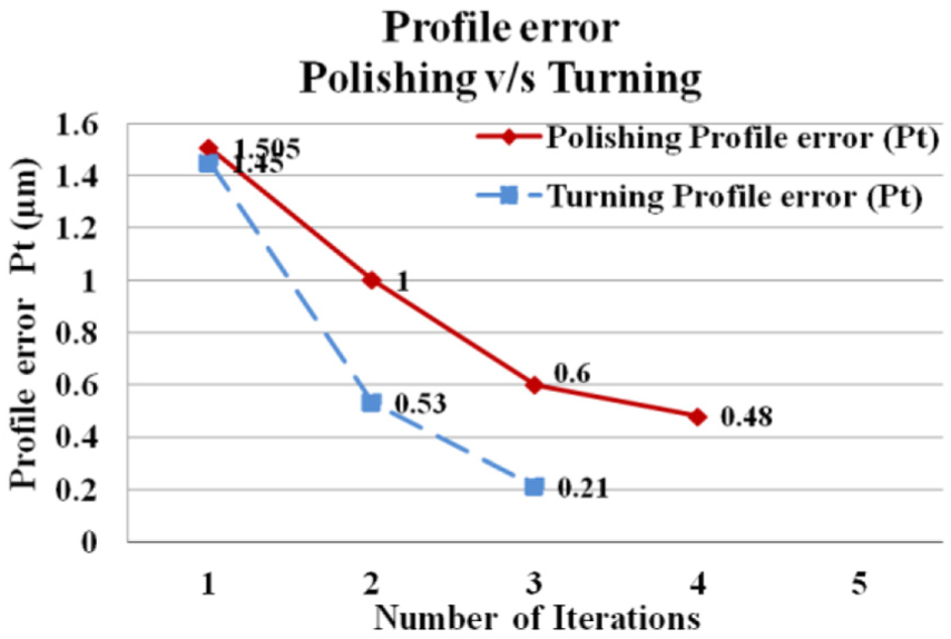
Comparison of the profile error during polishing and turning for compensation process.
Conclusion
The following conclusions are drawn from this study:
Aspheric silicon lens of diameter 13.6 mm is fabricated using the proposed hybrid approach comprising grinding and turning. Only three cycles, including two compensation cycles, are performed to achieve required ROC and profile accuracy.
The proposed hybrid approach will reduce the fabrication time, tool wear and cost for the production of aspheric silicon lenses.
Residual stresses stored during rough cutting of aspheric silicon by diamond tool, will also be overcome by this hybrid process.
Footnotes
Appendix 1
Acknowledgements
The authors thank Dr RamaGopal, Vice President, Optics & Allied Engg. Pvt Ltd, Bangalore, for his guidance.
Declaration of conflicting interests
The author(s) declared no potential conflicts of interest with respect to the research, authorship and/or publication of this article.
Funding
The author(s) disclosed receipt of the following financial support for the research, authorship, and/or publication of this article: This work was supported by the CSIR 12th Five-Year Plan (OMEGA).