
Abstract
The ultra-precision spindle is the key component of ultra-precision machine tool, which largely influences the machining accuracy. Its frequency characteristics mainly affect the frequency domain error of the machined surface. In this article, the error measurement setup for the ultra-precision aerostatic spindle in a flycutting machine tool is established. The dynamic and multi-direction errors of the spindle are real-time measured under different rotation speeds. Then, frequency domain analysis is carried out to obtain its regularity characteristics based on the measurement result. Through the analysis, the main synchronous and asynchronous errors with relatively large amplitude of the spindle errors are found, and the amplitude change law of these main spindle errors is obtained. Besides, the cause of the main synchronous and asynchronous errors is also analyzed and indicated. This study deepens the understanding of ultra-precision spindle dynamic characteristics and plays the important role in the spindle frequency domain errors’ control, machining process planning, frequency characteristics analysis and oriented control of the machined surface errors.
Introduction
With the development of precision optics, instrument, electronics and other related cutting-edge fields, high requirement for the parts’ surface accuracy has been raised. In some application fields, conventional requirement of surface roughness and figure accuracy is not the only demand and target any more, the frequency domain error requirement becomes more and more important. Ultra-precision machine tool is the irreplaceable equipment for the precision parts manufacturing. Ultra-precision spindle is the key component of the ultra-precision machine tool, whose error (or error motion) mainly influences the machining accuracy.1–4 Its frequency characteristics also mainly affect the frequency domain errors of the machined surface. Therefore, the measurement and analysis of ultra-precision spindle has great significance for deeply understanding the spindle performance and improving the machining quality.
Much work has been reported about the spindle error measurement, analysis and system development. Marsh and Grejda 5 described the master axis method for machine tool spindle measurement, which allowed the measurements to be carried out at speed and under load. Hii et al. 6 investigated the radial and tilt error motions of the prototype spindle using an analytical model and experimental measurements. The analytical model was used for the prediction of the synchronous error motion by roundness profile measurements of the rotor. Castro 7 developed a method to evaluate the radial and axial error motions of machine tool spindles using a laser interferometer. Khan and Chen 8 proposed a new method for error characterization and quantification of rotary joints of multi-axis machine tools using a calibrated double ball bar system as the working standard. Anandan and colleagues9,10 used a laser Doppler vibrometer (LDV)-based measurement method to analyze the radial and axial errors of a miniature ultra-high-speed spindle, and the results showed that the average radial motion, synchronous radial error motion value and the standard deviation of the asynchronous radial error motion varied significantly with the spindle speed due to dynamic effects. Besides, the sources of error motions were identified and quantified in their research. Madden et al. 11 presented a concurrent measurement method of spindle radial, axial and angular motions based on the concentric circle grating and phase modulation interferometers, in which the concentric circle grating with fine pitch is selected as the reference artifact. Geng et al. 12 measured the axial and radial errors of a high precision spindle by a novel atomic force microscopy (AFM)-based methodology. Nakkiew et al. 13 introduced a new and practical method to measure the radial error for the spindle with the attached cutter based on cutting mark measurement, which can be carried out at high-speed rotations without the reference sphere. Gao et al. 14 developed a measuring system for the spindle error and roundness measurement by three two-dimensional slope sensors. Ashok and Samuel15,16 used the capacitive sensor-based measurement technique to evaluate the radial errors of a miniaturized machine tool spindle and applied the harmonic analysis-based method for separation of form error during evaluation of radial errors. Murakami et al. 17 developed a simple optical measurement system for the simultaneous measurement of the 5-degree-of-freedom error motions of high-speed micro-spindles and demonstrated its effectiveness. Marsh et al. 18 conducted the experimental test to quantify the picometer-level vibration and its significant variation with both supply gas composition and pressure. Xiang et al. 19 proposed a vector–angle–cosine hybrid model for the spindle thermal error prediction, which combined the advantages of different constituent models (i.e. multivariable linear regression model, natural exponential model and finite element model). Besides, Xiang et al. 20 accurately predicted multi-degree-of-freedom spindle thermal errors by applying experimental modifications to preliminary theoretical models of the temperature field and thermal deformation. Akhondzadeh and Vahdati 21 investigated the influence of air pocket geometry and depth on air spindle vibrations through the experiment.
The available research result has lots of positive significance for the spindle error identification and characterization. However, little attention has been paid to the real-time measurement and analysis of frequency domain errors for the ultra-precision aerostatic spindle, especially for which in the ultra-precision flycutting machine tool. In this article, the dynamic error of the ultra-precision spindle in an ultra-precision flycutting machine tool will be real-time measured, before which the measurement setup will be introduced. Based on the measurement result, the frequency domain analysis of the spindle error will be conducted to obtain its regularity characteristics.
Error measurement setup of ultra-precision spindle
Basic concept of spindle error
Before the measurement and analysis of the spindle error, the basic concept should be introduced first. The spindle errors are usually classified by the spatial domain, which are axial error, radial error, tilt error and face error, respectively. However, in terms of frequency domain, they can be classified as synchronous error and asynchronous error.22,23 The synchronous errors are the components of total error motion that occur at integer multiples of the rotation frequency, and its value is the scaled difference in radii of two concentric circles from a specified error motion center just sufficient to contain the synchronous error motion polar plot. The asynchronous errors are the portions of the total error motion that occur at frequencies other than integer multiples of the rotation frequency, and its value is the maximum scaled width of the asynchronous error motion polar plot, which is measured along a radial line through polar chart center. In this article, these different kinds of spindle errors will be referred and analyzed.
Measurement setup
The measurement object is an aerostatic spindle of the ultra-precision flycutting machine tool. The spindle error analyzer of Lion Precision Company in United States is selected for the spindle error measurement instrument, which has multi-channel capacitance displacement sensors and ultra-precision master balls. It can be used to measure the axial and radial spindle errors simultaneously, and its minimum measurement resolution can reach 2 nm.
Due to the special structure of the flycutting machine tool, the flycutter head is fixed to the bottom of the spindle; therefore, it is difficult to measure the error in the bottom of the spindle. However, the spindle system adopts the motorized spindle structure, in which the connection of motor rotor and spindle is a rigid connection, and they can be treated as an integral structure. Thus, the master ball can be installed in the top of the spindle for the spindle error measurement. Figure 1 illustrates the schematic representation of spindle error measurement. It can be seen from Figure 1 that the dual master ball bar is installed in the top of the spindle, and five channel sensor probes (X, Y, Z, X2 and Y2) are used. Among them, the data from probe Z are used to get the axial error. The probes X and Y are installed on the same plane, which is the same as probes X2 and Y2. The data from these four probes can be used to get the radial error. The tilt error can be obtained based on the joint analysis from the data from probes X and X2 (or Y and Y2). The focus of this article is the frequency domain errors of the spindle errors, for which the measured data of axial and radial errors will be dealt with by fast Fourier transform (FFT) analysis.
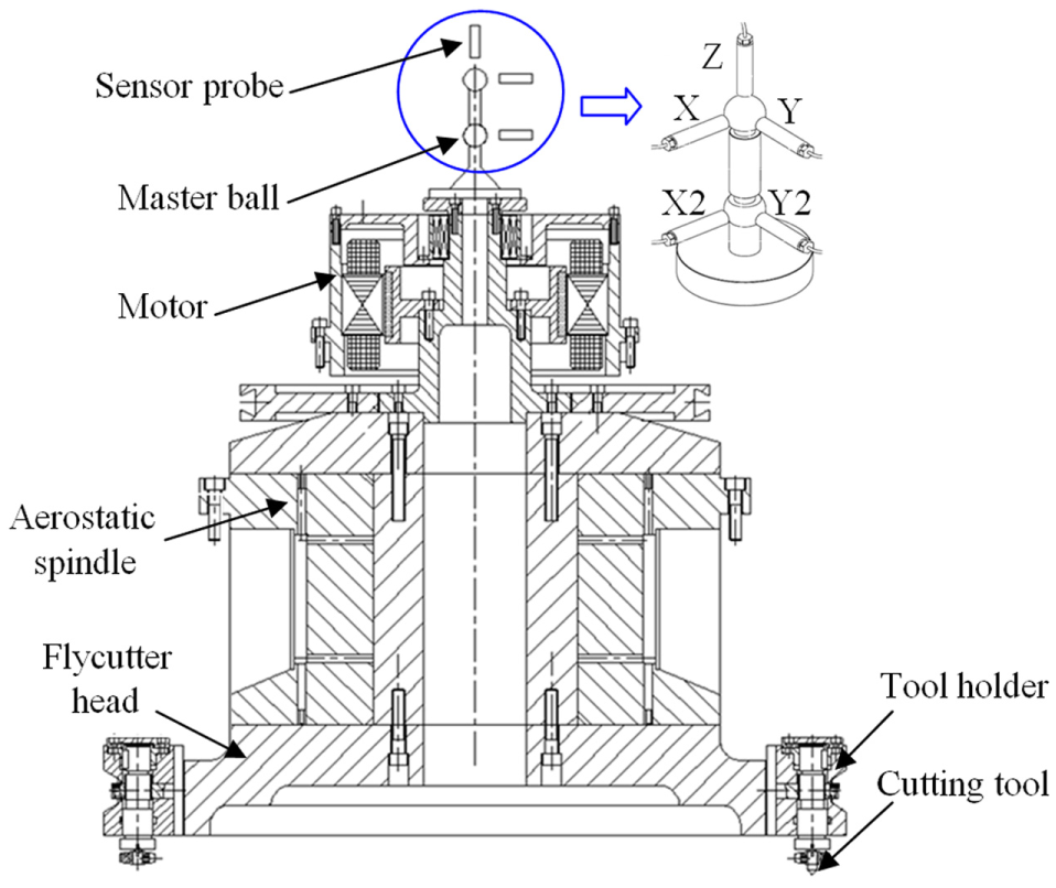
Schematic representation of spindle error measurement.
The spindle error measurement setup is shown in Figure 2. A self-made cylindrical sensor support device is installed in the top of machine tool for fixing the three-dimensional precision motion equipment, which is used to adjust the distance of sensor probe and dual master ball bar for meeting the measurement requirement of the instrument. For the better real-time sampling and analysis of dynamic error data, the dynamic signal analyzer of IOtech Company in United States is also used. This experiment belongs to ultra-precision measurement experiment, so it has high environmental requirements. The experiment is carried out in the clean room, in which the temperature and humidity are precisely controlled at around 21 °C and 18%, respectively. Besides, the machine tool is placed on the vibration isolation ground to minimize the environmental influence on the measurement results.
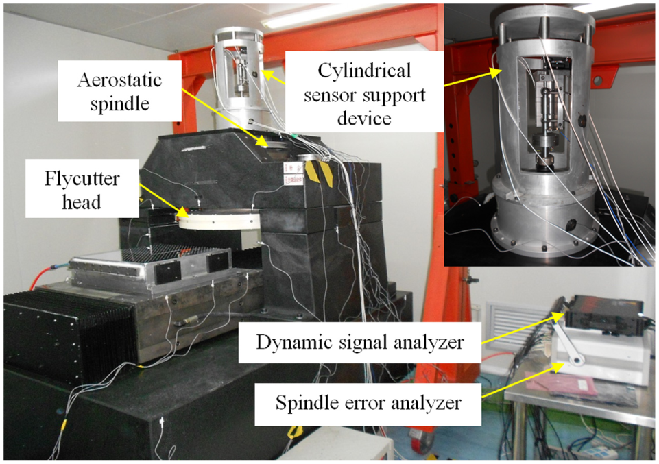
Spindle error measurement setup for ultra-precision flycutting machine.
Experiment and discussion
Experiment scheme
From Figure 1, it can be seen that the tilt error of the spindle can be deduced by the radial error data from the probes X and X2 (or Y and Y2) with the known axial distance between the two master balls. Besides, the face error of the spindle can be deduced by the axial error data from the probe Z and tilt error with the known radial distance between the cutting tool and spindle rotation axis. It means that the frequency characteristics of the radial and axial errors can basically represent the frequency characteristics of the spindle errors. In this article, therefore, only the radial error and axial error will be real-time and dynamically measured. In the radial error measurement, the frequency contents of the error data from different probes have the same frequency components, the difference of which is only reflected in the amplitude. Hence, only the radial error data from one probe are selected for the frequency domain analysis as the representative, which are the error data from probe X2 in this article. Each type of the spindle error has three times measurement and sampling, and the data are analyzed by the FFT to get the frequency components and corresponding root mean square (RMS) amplitudes. It should be mentioned that the spindle error is measured under the idling condition.
The axial and radial errors under different rotation speeds are measured for studying the influence of the rotation speed on the spindle errors. Considering that the used rotation speed of the chosen spindle in the actual flycutting is usually more than 200 r/min and less than 400 r/min, therefore, 15 groups of experiments with different rotation speed values between 210 and 390 r/min are carried out.
Results and discussion
After the experiments, the main frequency components of spindle axial and radial errors can be obtained. The main frequency components mean the corresponding amplitudes that rank in the top three and have the dominant influence. The main frequency components of spindle axial errors are shown in Table 1. In Table 1, RS and FQ stand for rotation speed and frequency, respectively. Besides, the listed frequency components under every rotation speed are sorted by its corresponding amplitudes; that is, the corresponding amplitude of FQ 1 is bigger than FQ 2, and the corresponding amplitude of FQ 2 is bigger than FQ 3.
Main frequency components of spindle axial error.
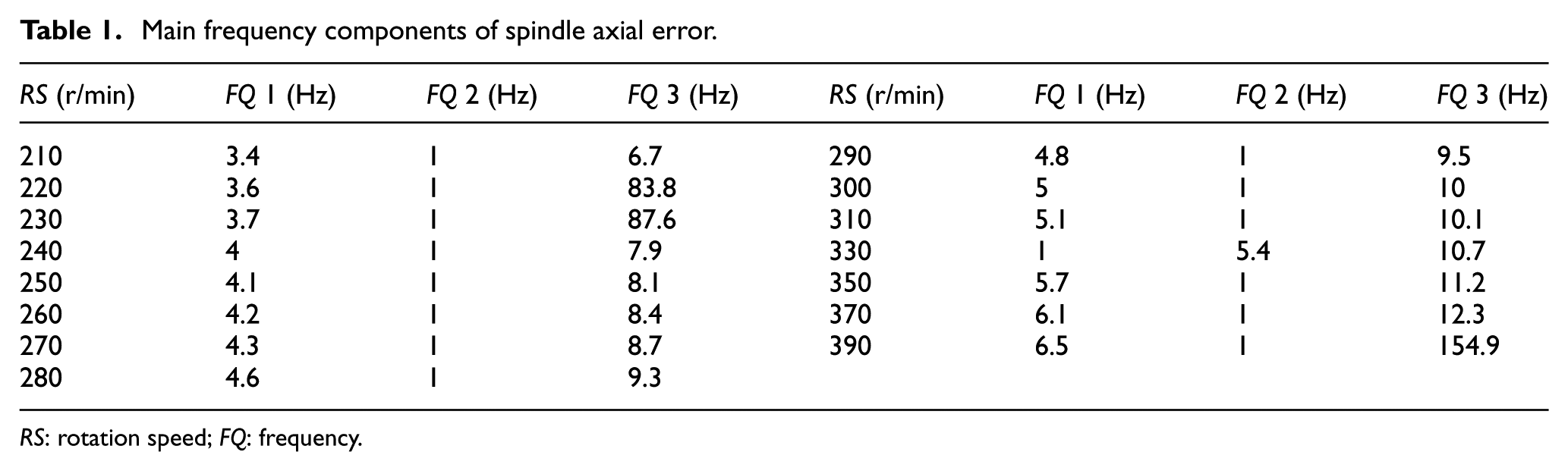
RS: rotation speed; FQ: frequency.
From Table 1, it can be found that the main frequency components under each rotation speed condition contain 1-fold frequency, 2-fold frequency and 24-fold frequency of the rotation frequency (i.e. the 60th of RS) and a low-frequency component of 1 Hz. It indicates that the axial errors mainly consist of synchronous errors and a low-frequency asynchronous error. It should be mentioned that due to the actual rotation speed in the experiment has a little difference with the theoretical value of the setting value and the FFT analysis has some error, the actual fold frequency value is not absolutely the same as the theoretical calculating value. Besides, some interference frequency components (i.e. non-spindle error frequency components) are excluded by the comparative experiments. For instance, the error measurements under the conditions of static spindle and slide and static spindle and moved slide are also carried out. The obtained frequency characteristics under these two conditions are compared with that of actual rotation error measurement, by which some interference frequency components can be known and excluded in the actual analysis.
The main frequency components of spindle radial errors are shown in Table 2. It can be seen that the main frequency components under each rotation speed condition contain 2-fold frequency, 3-fold frequency, 12-fold frequency and 24-fold frequency of the rotation frequency and a low-frequency component of 1 Hz. It also indicates that the radial errors also mainly consist of synchronous errors and a low-frequency asynchronous error.
Main frequency components of spindle radial error.
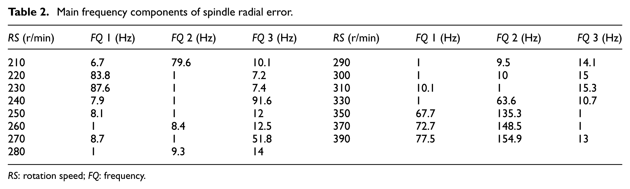
RS: rotation speed; FQ: frequency.
In the following, the key attention will be paid on the analysis of main synchronous errors under different rotation speeds. Due to the influence of structural component error and assembly error of the spindle, the frequency components of radial error, especially the one with high amplitude, have some influence on the frequency components of axial error. Therefore, the RMS amplitude change of the main axial and radial synchronous errors under different rotation speeds is further analyzed. In the amplitude analysis of axial synchronous errors, 12-fold frequency error is also considered besides 1-fold frequency error, 2-fold frequency error and 24-fold frequency error. In the amplitude analysis of radial synchronous errors, 2-fold frequency error, 3-fold frequency error, 12-fold frequency error and 24-fold frequency error are considered.
The RMS amplitude of axial synchronous errors under different rotation speeds is shown in Figure 3. It can be seen that the RMS amplitudes of 1-fold frequency error, 2-fold frequency error and 12-fold frequency error vary relatively steady under different rotation speeds; nevertheless, the 24-fold frequency error changes relatively larger than others. Besides, as for the amplitude value, the onefold frequency error ranks the first, which is approximately 80–90 nm under different rotation speeds. Basically, twofold frequency error follows, and its amplitude value is about 20 nm. The 24-fold frequency error ranks the third, except under three rotation speeds of 220, 230 and 390 r/min. The last one is 12-fold frequency error, whose amplitude is less than 10 nm.
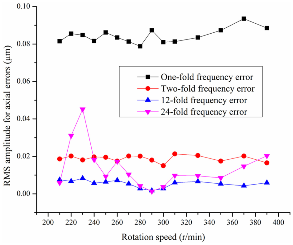
RMS amplitude of axial synchronous errors under different rotation speeds.
The RMS amplitude of radial synchronous errors under different rotation speeds is shown in Figure 4. It can be seen that the RMS amplitudes of 1-fold frequency error and 3-fold frequency error vary relatively steady under different rotation speeds, whereas, the 12-fold frequency error and 24-fold frequency error change relatively large; especially, under the rotation speed over the 300 r/min, the latter one has the change of the value order. It indicates that the increase in the rotation speed has more influence on the amplitudes of 12-fold frequency error and 24-fold frequency error. In Anandan et al., 9 the capacitive sensor-based measurement technique was also used to evaluate the radial error values of a miniaturized machine tool spindle, in which the radial synchronous errors under various spindle speeds were also analyzed. Their results showed that the spindle speed did not have much influence on synchronous radial error of the spindle. To some extent, this trend is similar to that of the results for the twofold and threefold frequency errors in this study. However, for the 12-fold frequency error and 24-fold frequency error, this trend is not applicable because the cause of these two errors is different from that of the 2-fold and 3-fold frequency errors, which will be explained in the following text. Also, it must be mentioned that the spindle speeds selected for the experimental analysis are under the low-speed range in this study.
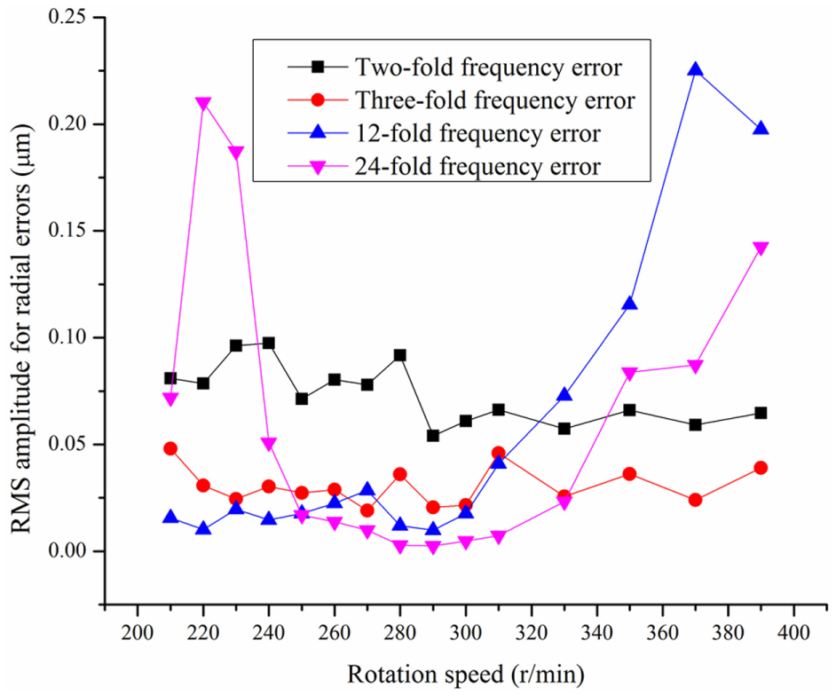
RMS amplitude of radial synchronous errors under different rotation speeds.
Based on the comparison of Figures 3 and 4, it can be found that the amplitude and variation range of the radial synchronous errors is larger than that of the axial synchronous errors with respect to the same frequency errors. Besides, for the 12-fold frequency error and 24-fold frequency error, if the RMS amplitude of its radial error is relatively large, then that of the corresponding axial error is also relatively large. It indicates that the amplitude change of radial errors has large influence on the amplitude change of axial errors, which means that improving the radial accuracy at the above-mentioned two frequencies will globally improve the spindle rotation accuracy at the corresponding frequencies from the viewpoint of engineering.
Based on the above analysis, the errors of spindle rotation mainly consist of synchronous errors, whose main frequency components contain three relatively low-frequency components of 1-fold frequency (only in axial direction), 2-fold frequency and 3-fold frequency and two high-frequency components of 12-fold frequency and 24-fold frequency. From the view of rotor dynamics, it is considered that the three low-frequency components are mainly caused by the unbalance response of spindle system, which is usually caused by the defects of spindle stator and rotor and the assembly stress. Due to the unbalance effect of the spindle in the radial direction is larger than that in the axial direction, the amplitude and variation range of the radial synchronous errors is larger than that of the axial synchronous errors for the same frequencies under different rotation speeds. In the experiment, the spindle rotation frequency is low and much less than the spindle inherent frequency, and the unbalance response can be approximately considered to be proportional to the square of the rotation frequency and inversely proportional to the square of the spindle inherent frequency; therefore, the amplitudes of synchronous errors induced by the unbalance response change are relatively small under different rotation speeds.
Through the analysis, the two relatively high-frequency components (12-fold frequency and 24-fold frequency) are considered to be mainly caused by the torque fluctuation of the drive motor. The reason is that under the low spindle rotation frequency, the error frequencies generated by the rotor and air bearing components are relatively low, which basically will not induce the error frequencies of over 12-fold frequency. However, the spindle motion is driven by the brushless direct current (DC) motor, so the drive torque fluctuation is inevitable in the motion driving process. Besides, the number of motor pole pairs is 6; that is, there are 12 pieces of magnet steel, which is basically corresponding to the multiple number of the rotation frequency (12 and 24). Thus, it is reasonable to consider that the torque fluctuation is the main cause of the two frequency components. With the increase in the rotation speeds, the input energy and electromagnetic force become larger, meanwhile, the torque fluctuation increases and finally results in the amplitude increase in the synchronous errors induced by torque fluctuation. Therefore, the 12-fold frequency error and 24-fold frequency error change relatively large with the change of rotation speeds.
In the main spindle errors, there is a low-frequency asynchronous error of 1 Hz that should not be neglected besides the above-mentioned synchronous errors. It can be seen from Tables 1 and 2 that the RMS amplitude of this asynchronous error basically ranks the second in the axial errors and radial errors. Figure 5 shows its amplitude change under different rotation speeds. It can be found that its amplitude change under different rotation speeds is relatively large, and the amplitude value is also relatively large. However, the frequency value of this asynchronous error under different rotation speeds is the same, which is 1 Hz in the experiment, all less than the rotation frequency. Considering the actual condition of aerostatic spindle, this asynchronous error is thought to be mainly induced by air-film vibration. However, the air film will be not completely the same in different long periods; therefore, it is speculated that the frequency value of this asynchronous error may have some change in different periods, but the change will be limited in a certain small range.
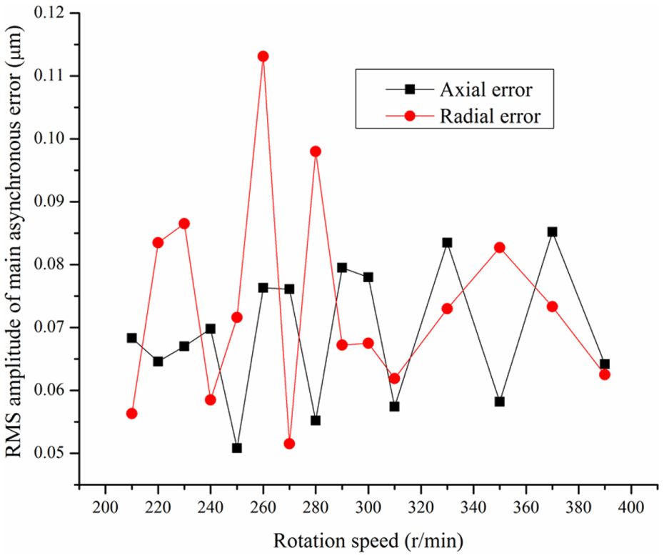
RMS amplitude of main asynchronous error under different rotation speeds.
The results of the above analysis deepen the understanding of ultra-precision spindle dynamic characteristics and lay the foundation for follow-up study, such as spindle frequency domain errors control, machining process planning, frequency characteristics analysis and oriented control of the machined surface errors. Further study will focus on the detailed analysis on the generation mechanism of the main frequency domain error for the ultra-precision spindle from the perspective of motor-bearing-rotor-coupling system.
Conclusion
This article carries out the real-time error measurement of the ultra-precision spindle in a flycutting machine tool, and the detailed frequency domain errors for the axial and radial errors are analyzed. Through the above study, the following conclusions can be drawn:
An experimental setup for the error measurement of the ultra-precision spindle is built, based on which the multi-direction spindle errors under different rotation speeds are real-time measured. It is indicated that the frequency components of the axial and radial errors can be used as the representative of the frequency components of spindle errors.
The frequency domain analysis of the axial and radial errors is conducted. The results show that the spindle errors mainly consist of synchronous errors, whose main frequency components contain three relatively low-frequency components of 1-fold frequency (only in axial direction), 2-fold frequency and 3-fold frequency and two relatively high-frequency components of 12-fold frequency and 24-fold frequency. Besides the five main synchronous errors, the main spindle errors also contain a low-frequency asynchronous error. The RMS amplitude change law of the main spindle errors is obtained. The amplitude and variation range of the radial synchronous errors is larger than that of the axial synchronous errors for the same frequencies under different rotation speeds. Besides, with the increase in rotation speeds, the amplitudes of three relatively low-frequency components change relatively small and that of the two relatively high-frequency components change relatively large, especially in the radial direction.
The cause of the main synchronous and asynchronous errors is analyzed. It is considered that the three relatively low-frequency synchronous components (i.e. 1-fold frequency, 2-fold frequency and 3-fold frequency) are mainly caused by the unbalance response of spindle system, and the two relatively high-frequency components (i.e. 12-fold frequency and 24-fold frequency) are mainly caused by the torque fluctuation of the drive motor. Besides, the low-frequency asynchronous error is analyzed to be mainly induced by air-film vibration.
Footnotes
Declaration of conflicting interests
The author(s) declared no potential conflicts of interest with respect to the research, authorship and/or publication of this article.
Funding
The author(s) disclosed receipt of the following financial support for the research, authorship, and/or publication of this article: This work was supported by Zhejiang Provincial Natural Science Foundation of China (No. LQ16E050012), National Science Fund for Distinguished Young Scholars of China (No. 50925521), National Natural Science Foundation of China (No. 51275115) and Program of International S&T Cooperation (No. 2015DFA70630).