
Abstract
In flank milling, the machined metal surface is formed by the edge of the cutting tool and is thus affected by tool errors. Cutting tool rotation errors affect the movement of the tool teeth and thus change the trajectory of the tool edge. This change will also affect the cutting force, which will result in deformation in the cutting process. Previous studies focus mostly on the cutting tool runout error and ignore the effect of tool deformation. In this article, we built a mathematical model of the machining process that considers not only the tool runout error but also the tool tilt deformation error. Using this model, we analyzed how the tool rotation error will influence workpiece surface quality and surface frequency. Results show that feed rate and rotation errors will affect surface roughness, geometric error, and surface energy distribution.
Introduction
Five-axis milling is widely used in machining many types of workpieces such as aircraft structural parts, blades, and impellers.1–4 The advantage of flank milling is that it can expand the process range and improve the machining quality and efficiency compared to ball-end cutter point milling.5–9
The processing error mechanism and its control strategies in flank milling have attracted the attention of many researchers. Previous research has revealed the effect of tool deformation, tool wear, flutter, and kinematic error on machining error. Ways of reducing errors by parameter selection and error compensation have been developed. To reduce the deformation error of the machining process, many studies of machining force and error compensation strategy have been made. Kilic and Altintas 10 presented a dynamic model of peripheral milling systems with axially varying dynamics. Ahn et al. 11 generated many force calibration data through Monte Carlo simulation to study the relationship between error of the predicted cutting forces and the error index. Zhang et al. 12 presented an analytical prediction of contouring errors in the five-axis machining of splinted tool paths and developed a method of error compensation. Srikant et al. 13 studied the influence of emulsifier content in cutting fluids on cutting forces, cutting temperatures, tool wear, and surface roughness. Tuysuz et al. 14 presented a mechanical model to predict the cutting force by modeling the chip thickness distribution. Traditional machine strategies and compensation methods do not consider tool rotation errors, which cause errors in the simulation and compensation process. Wang et al. 15 developed an adaptive smart machining method based on using constant cutting force and a smart cutting tool to automatically control cutting force in the machining process. With constantly increasing demand for manufacturing precision, more and more researchers have begun to study how tool rotation errors affect the machined surface.
Tool runout includes tool setting error and cutter grinding errors.16,17 These studies focus mostly on simulating and measuring tool runout errors. Li et al. 18 proposed a feature-based machine tool accuracy analysis method to evaluate machine tool capability. The cutter is used as a bridge for the kinematic transformation and the geometrical relationship construction in the method. In his method, component error and rotation error are considered as elements in error analysis. Yu et al. 19 studied the machined surface formed by a specially designed cutting edge under cutter runout error, including axis runout error and tilt error, in flue-axis flank milling and studied special cases of the analytical model and the runout effect on the envelope surface. Liu et al. 20 studied the spectral characteristics of milling force for chip load, tool wear, and tool runout in the end milling process to distinguish them from each other and proposed a new method of identifying tool eccentricity and wear with force. Franco et al. 21 studied the influence of back-cutting on the surface finish obtained by face milling operations, modeled the final part’s surface roughness from tool runouts and height deviations that affect the surface marks initiated by back-cutting, considered round insert cutting tools and surface positions defined by cutter axis trajectory, and developed milling experiments. Arizmendi and colleagues22–24 developed a new model to predict the effects of tool parallel axis runout error and cutter axis tilt on the topography of the machined surface in flank milling and developed a method to identify the tool parallel axis runout through the analysis of the topography of surfaces machined by flank milling. Yang and Liu 25 studied the surface generation mechanism in peripheral milling with variable-pitch end mills and proposed a corresponding surface generation model to predict the generated surface topography incorporating the cutting process parameters and several sources of machining error such as tilting, runout, deformation of the tool, and workpiece displacement. Diez et al. 26 proposed a methodology to evaluate tool runout in peripheral milling using a piezoactuator-based system that allowed tool runout compensation by controlling workpiece displacement.
In this article, we focus on the flank milling process and study the influence of cutting tool runout error and tilt error on the cutting force and the machined surface. A machining process model is built to study the influence of tool rotation error on the tool teeth movement in “Influence of tool rotation errors on tool tip movement.” In section “Influence of tool rotation errors on machining force and tool deformation,” the cutting force model influenced by tool rotation errors is studied, and the tool deformation error caused by the cutting force is calculated. The machined surface simulation results of the milling process model are also presented. The influence of tool rotation errors on surface topography is discussed in section “Simulation and analysis of machined surfaces.”
Influence of tool rotation errors on tool tip movement
Generally, the quality of the machined surface depends on the positional accuracy of the tool tip relative to the part being machined. The key to machined surface model is tool tips’ position. Tool rotation errors are errors in the tool rotation movement. These errors may have multiple causes, including spindle-rotation-induced error in numerical control (NC) machines, cutting tool assembly error, and cutting tool manufacturing error. All these errors lead to two errors of the rotational movement of the tool: runout error and tilt error.
Figure 1 shows how the tool runout error affects the rotational motion of the tool. The runout of the tool causes the tool to rotate around the rotating axis instead of its own axis, which causes a difference between the tool tip rotating radius and the ideal one.
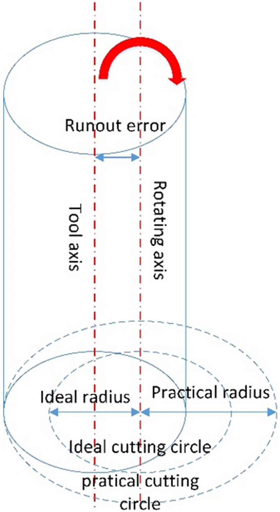
Tool runout error.
The practical tooth rotation movement of one cutting tooth influenced by tool runout error is shown in Figure 2. Tool runout error can be defined by two parameters: the runout angle a and the runout magnitude d. The runout angle a shows the direction of the tool runout error and is the angle between the tool runout error and the direction of the first tooth when z is zero.
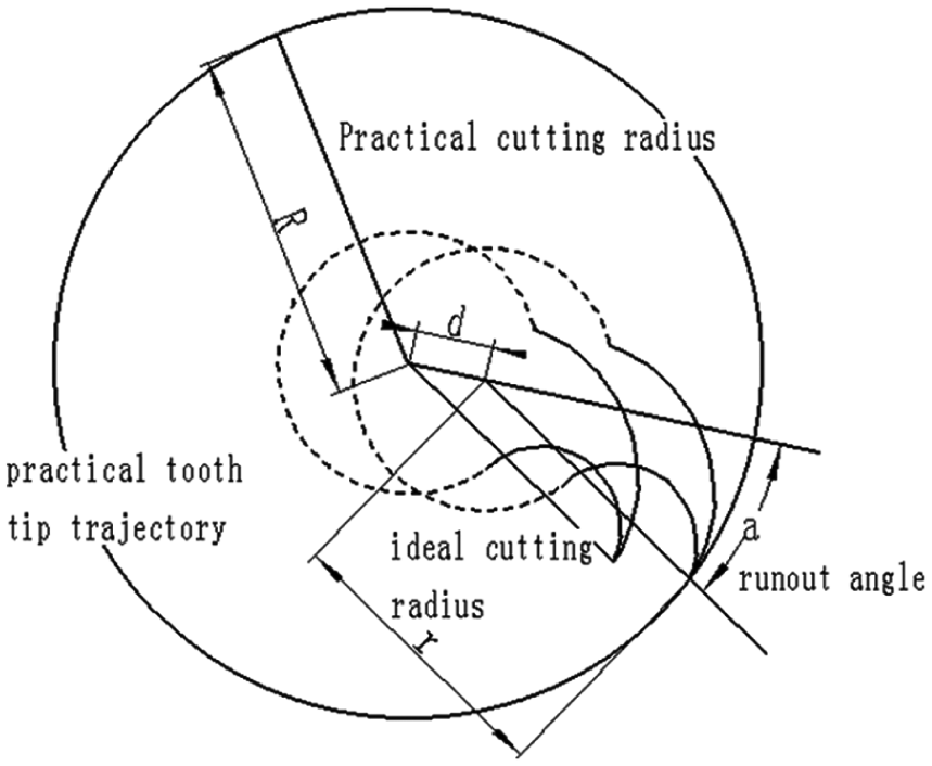
Cross section of practical tool rotation movement.
The influence of tool tilt on tooth tip movement is determined by two parameters. The first is the tilt angle, which is the angle between the tool axis and its revolving axis; this angle gives the magnitude of the tool tilt error. The other parameter is the angle
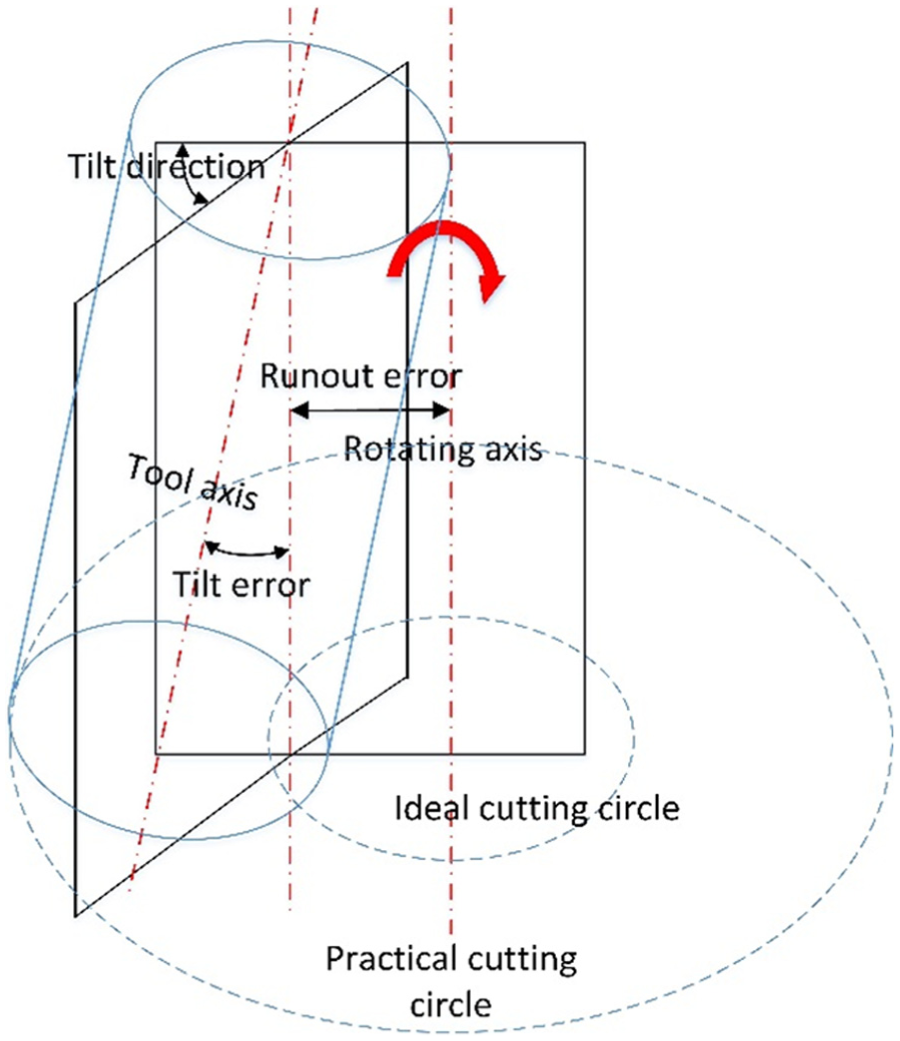
Tool runout and tilt error.
Runout error and tilt error have a combined effect on the deviation of the cutting tool axis and thus change the revolving circle of each tooth tip of the tool. Figure 4 shows the real rotating radius of the first tool tip influenced by both tool runout error and tilt error.
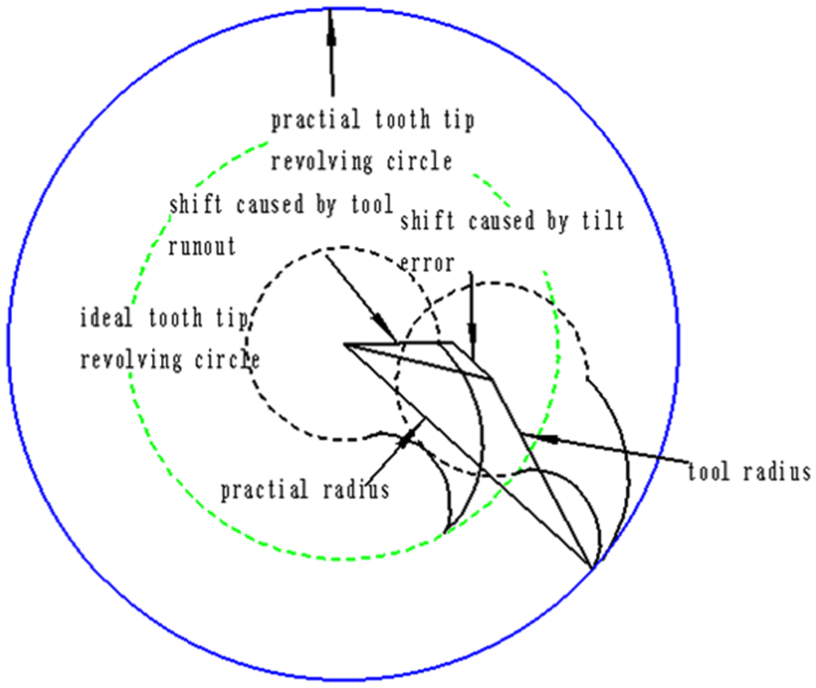
Tool edge radius with tool rotation error.
From the geometric relationship shown in Figure 4, we can determine the practical cutting radius through a triangle formed by the ideal cutting radius, the practical cutting radius, and the shift caused by tool rotation errors. A tool coordinate axis is established to define the positional relationship of the tool teeth tips and the tool spindle axis, which reflects the actual cutting condition taking into consideration the tool rotation errors. The z-axis is the cutting tool rotation axis, the coordinate origin is the intersection of the tool’s top surface and the z tool axis when the cutting process starts, and the x-axis is the feeding direction during the machining process.
From Figure 4, we can determine the real rotating radius of the first tooth tip at height 0
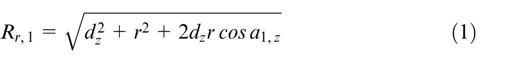
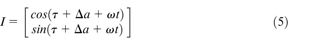
where
The rotating radius of the ith tooth tip at height z is
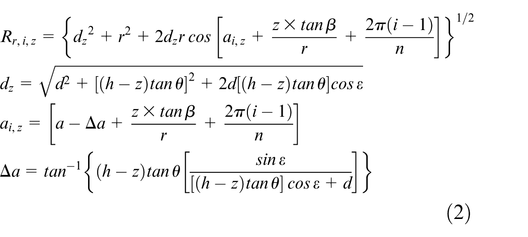
where
The machined surface is formed by the movement of the tips of the cutting tool teeth. To analyze the influence of tool rotation errors on the machined surface topography, the trajectory of tool tooth tips is needed.
The teeth tips of the milling cutter turn around the revolving axis, and the revolving axis moves at a constant speed. The practical teeth trajectories become trochoidal. In the machining process, machining force causes the deformation of the cutting tool. The coordinate position of the tooth tip can be expressed as
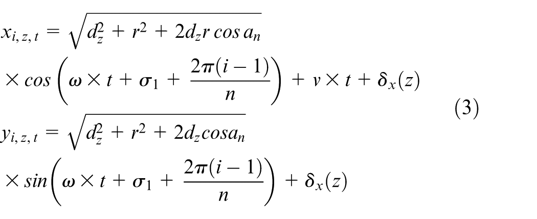
where
In the model, the origin of coordinate system is built on the center of tool end. The simulation can be expended to five-axis machining process through homogeneous transformation matrices (HTM) method and rigid-body assumption theory.
Influence of tool rotation errors on machining force and tool deformation
Machining force and tool deformation cause geometric deviations in a machined workpiece. During the last decade, much research has been done to predict the part deformation due to material processing.
27
To calculate the tool deformation errors
To simplify the simulation process, the cutting part of the tool is divided into
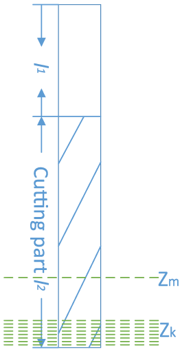
Cantilever beam infinitesimal element model.
The centrifugal force of the cutting tool at height z is

where I is direction vector of the centrifugal force
where
Previous study has shown that the cutting force of an infinitesimal element of the tool at height z can be calculated through the chip thickness 28
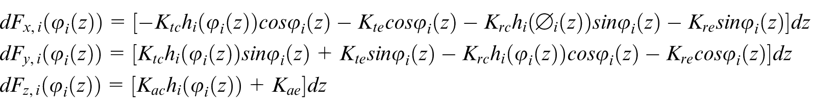
In most milling process models, the instantaneous uncut chip thickness is approximated as

The relative error in chip thickness increases when
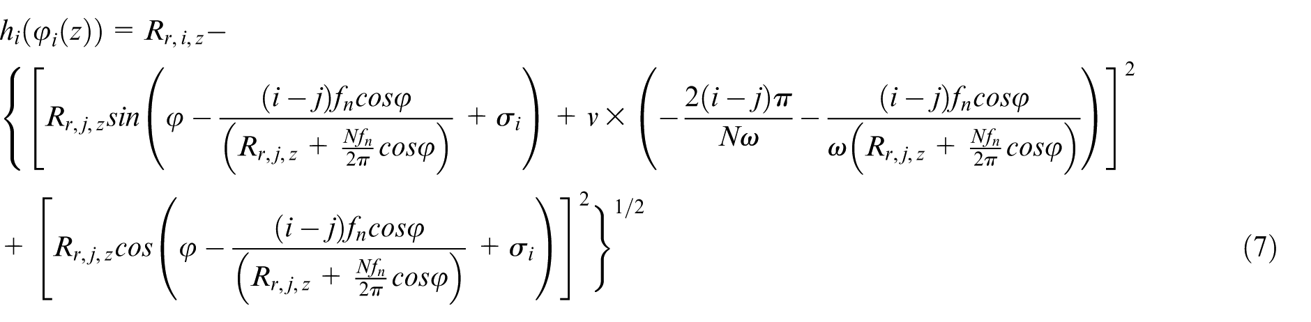
where
At height
The deformation on the tooth part of the tool at height
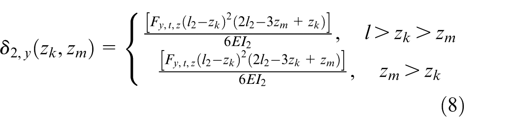
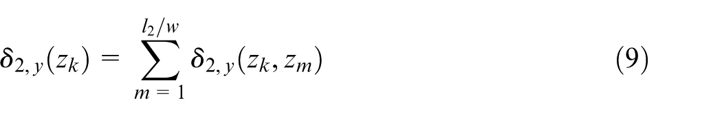
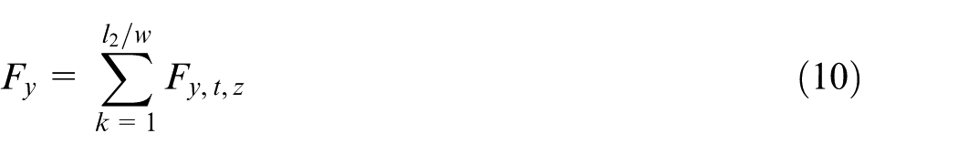
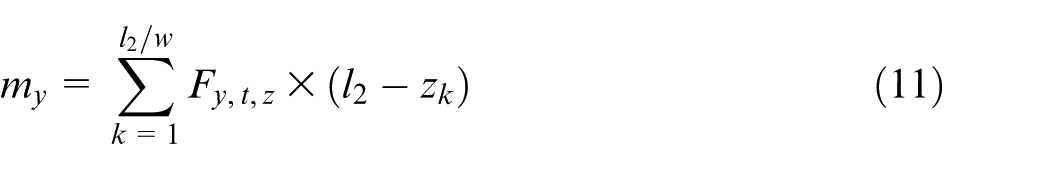
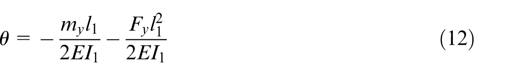
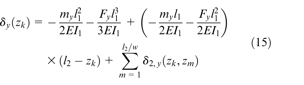
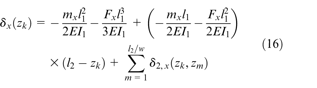
The total deformation of the tool can be calculated using the superposition principle. The deformation at any height equals the sum of the deformation caused by forces on each segment of the tool
On part
The deformation and deflection of
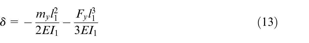
At height
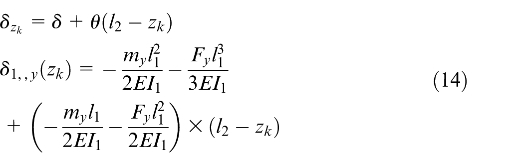
Total deformation in the y-direction is
The deformation in the x-direction can be calculated in the same way, which is
Simulation and analysis of machined surfaces
Machined surface quality
To illustrate the influence of tool errors on the machined surface, a particular manufacturing case shown in Table 1 is considered.
Simulation case.
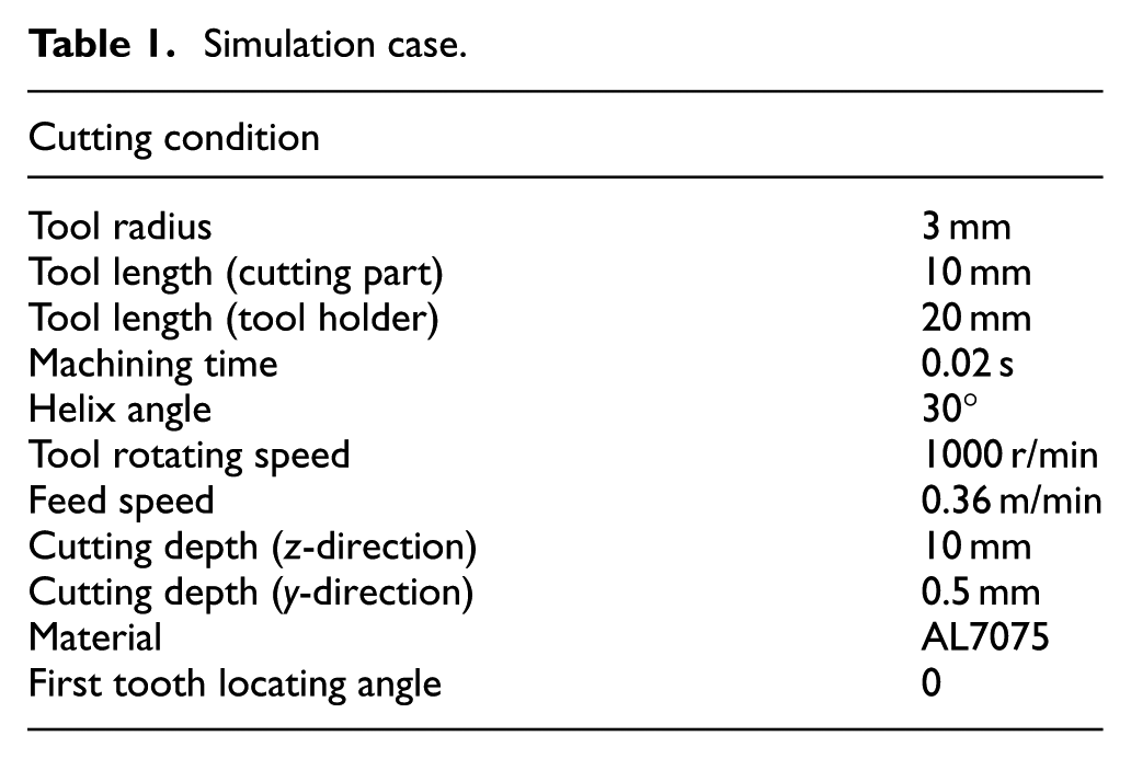
Figure 6 shows the simulation results of a four-tooth tool machined surface under different tool runout error conditions with zero tilt error. As the runout error increases, the cut of the surface becomes deeper, the surface is gradually formed by only one tooth, and the amplitude of the machined surface increases. The practical rotating radius of each tooth of the cutting tool changes with the cutting depth z as shown in equation (2), causing the change of surface topography in the z-direction.
Simulated surface machined by a four-tooth tool: (a) with no tool rotation error, (b) with a 2-µm runout error, (c) with a 5-µm runout error, and (d) with a 10-µm runout error.
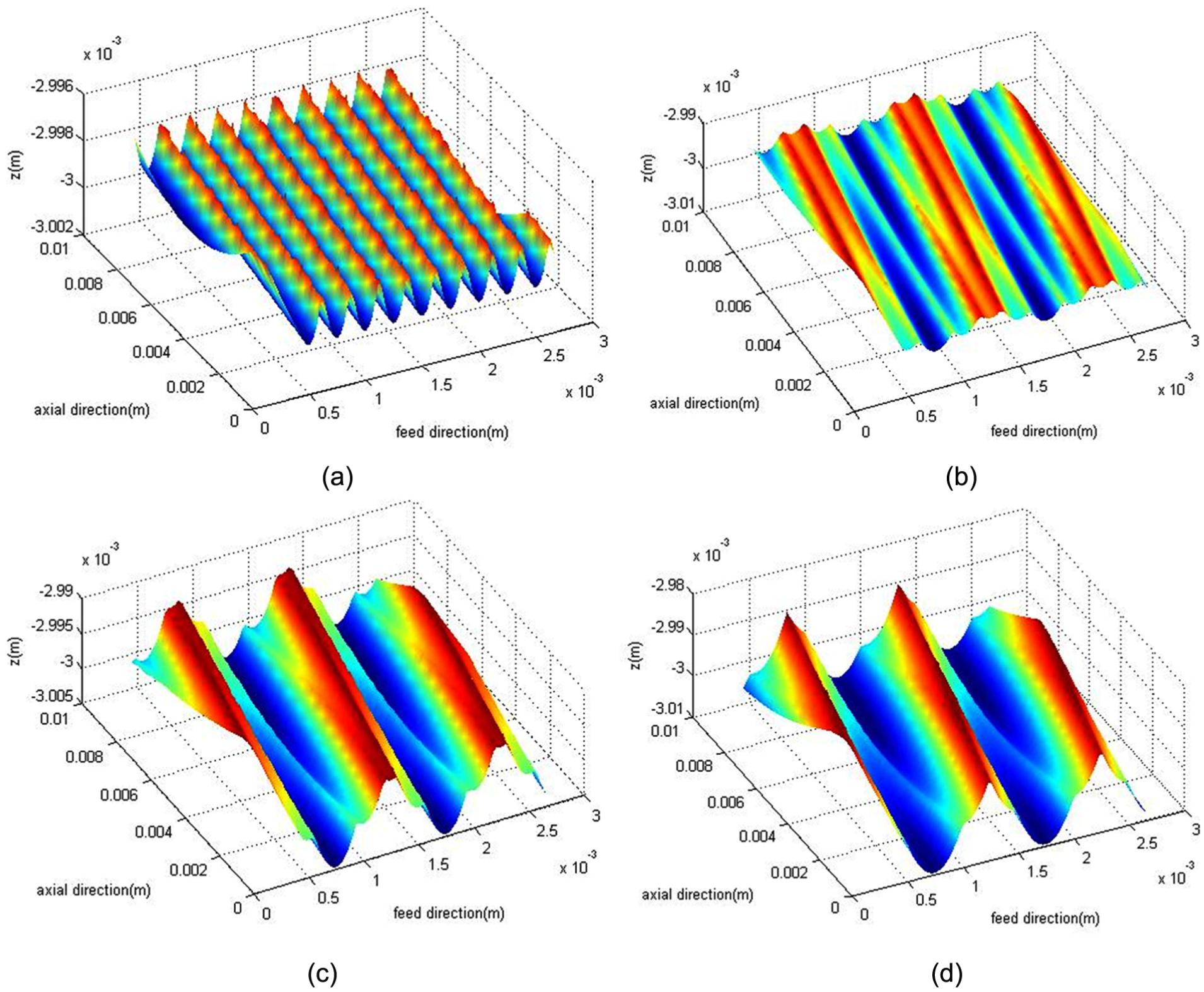
Figure 7 shows the simulation results of a two-tooth tool–machined surface at different tool tilt error conditions with no runout error. The result of the simulation shows that the tool runout error and tilt error have similar influence on surface topography and quality. The undulation of the surface increases with the tool rotation error, and therefore, the roughness of the machined surface will increase with the tool rotation error. Through a set of simulations, we find that before the error reaches a threshold value, surface roughness increases linearly with rotation errors. After that value, surface roughness slowly decreases. In the simulation case, the minimum surface roughness is 0.5 µm, while the maximum surface roughness is 2.2 µm, which means that tool rotation error will cause 360% extra surface roughness.
Simulated surface machined by a two-tooth tool with (a) a 0.0001-rad tilt error, (b) a 0.0002-rad tilt error, and (c) a 0.0005-rad tilt error.
The difference between the influence of tool runout error and tool tilt error is that the effect of the tilt error changes with the change of the machining depth z.
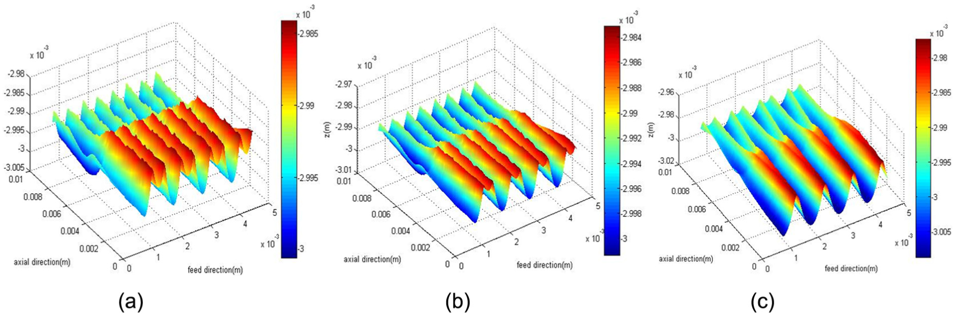
Figure 8 shows the simulation results of a two-tooth tool–machined surface under different feed rates with a 10-µm tool runout error and a 0.001167-rad tool tilt error, which are the errors measured in a rotation error experiment with a 6-mm-diameter cutting tool. The result of the simulation shows that the influence of tool rotation errors on surface topography decreases with increasing feed rate. Surface roughness decreases about 50% when feed speed increases from 0.05 to 0.3 m/min.
Simulated surface machined by a two-tooth tool with a 10-µm runout error and a 0.001167-rad tilt error: (a) feed speed 0.05 m/min, (b) feed speed 0.1 m/min, and (c) feed speed 0.3 m/min.
In conclusion, tool rotation errors cause undulation and cutting depth of machined surface, causing special topography. The effect of the tool error increases with both runout error and tilt error, whereas it decreases with feed rate.
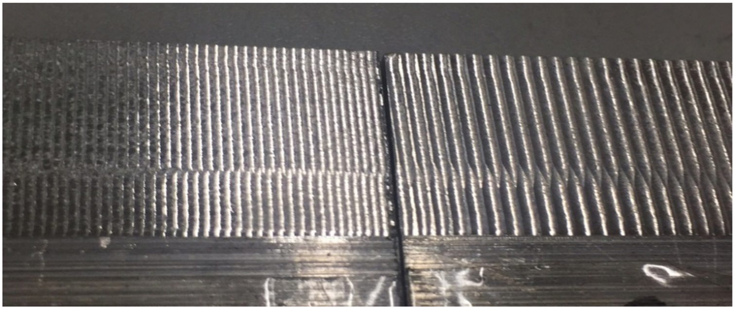
Machined surface topographies similar to those shown in Figures 6(d) and 7(c) viewed in cutting experiments have been reported by other researchers (Figure 9). 22
Photograph of the machined surface influenced by tool rotation error. 22
Machined surface frequency
From Figures 6–8, we can see that that if tool rotation error exists, the machined surface undulates each time the tool rotates. As a result, tool rotation error changes the machined surface frequency. In this article, power spectral density (PSD) is used to analyze the surface frequency.
Figure 10 shows the one-dimensional PSD calculation result of a machined surface. At each cutting depth z, the PSD is calculated, and the results are combined to form a PSD surface. From Figure 10, we can see that when the axial direction cutting depth is 0–4 mm, the PSD value remains almost the same, which indicates that in this area, the surface is formed by one tooth. When the axial direction cutting depth is 7.5 mm, the PSD value reaches a minimum, which indicates that at this depth, the practical runout angle is
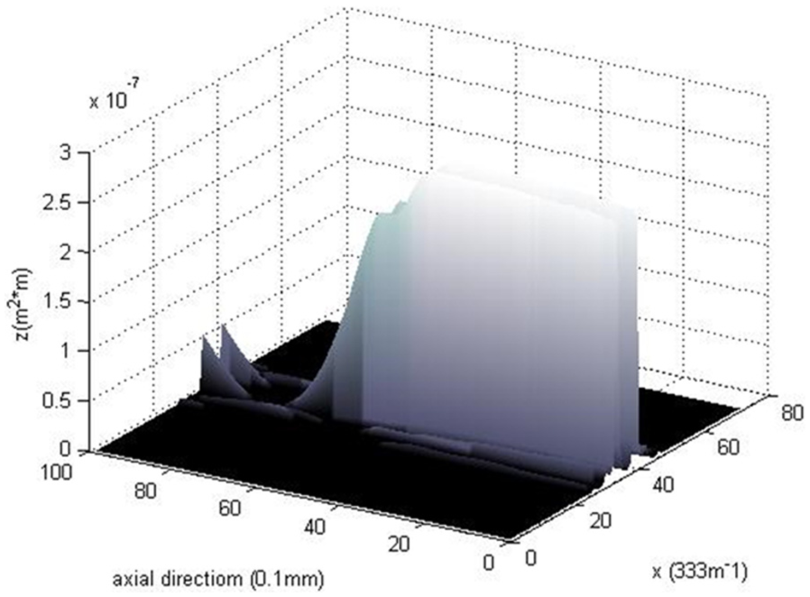
One-dimensional power spectral density of rotating frequency with a four-tooth tool.
The tool rotation errors increase the PSD of the surface with tool rotating frequency and decrease the PSD of the surface during tool feeding with tooth frequency. Estimation of the tool rotation error can be made by comparing PSDs for different surface frequencies.
Experiment
In the validation experiment, the cutting conditions are the same as in the case studied in section “Simulation and analysis of machined surfaces,” except the tool length (tool shank from holder), feed speed, and helix angle. The length of the tool shank was set to be longer (30 mm) for accuracy in the tool rotation error measuring process. Feed speed is adjusted in the machining process, and the helix angle is changed into 58°.
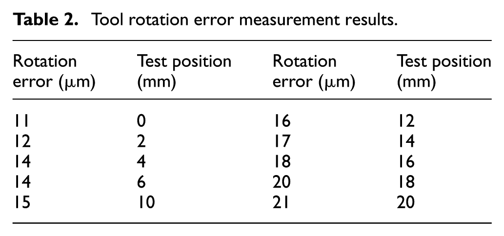
Tool rotation errors are measured before the cutting procedure by laser interferometer. The resolution of the measuring system is 0.1 µm.
In the tool rotation error measuring process, we found that if the rotation speed is below 800 r/min, rotation errors become unstable. For stability and accuracy, the tool rotating speed is 1000 r/min in the testing and cutting process. The error test results are listed in Table 2.
Tool rotation error measurement results.
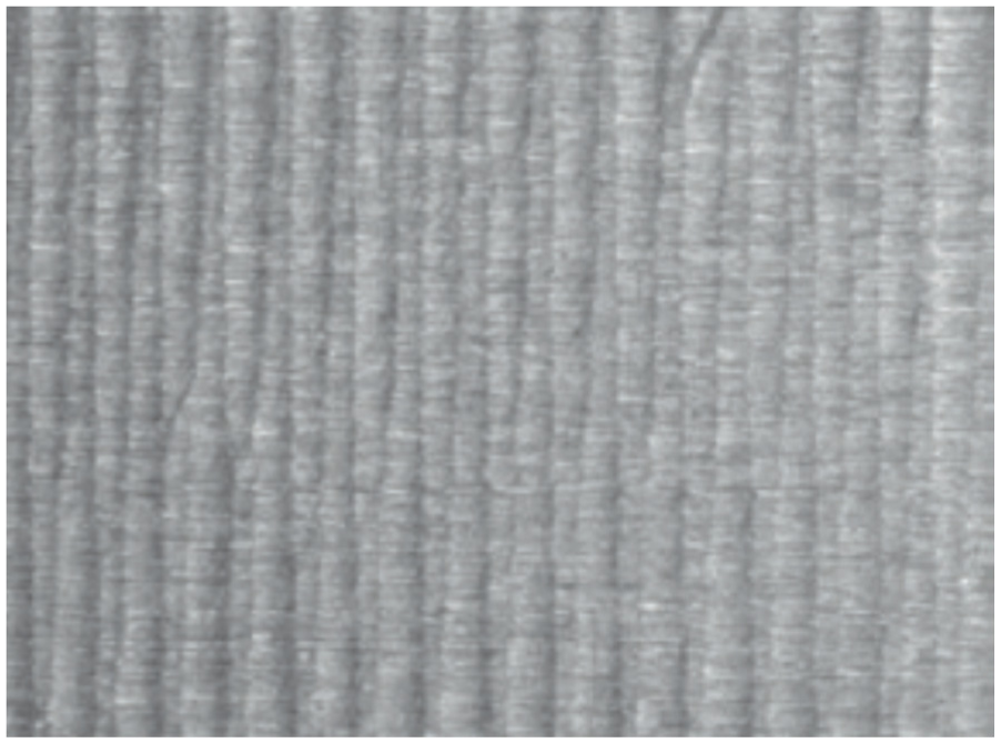
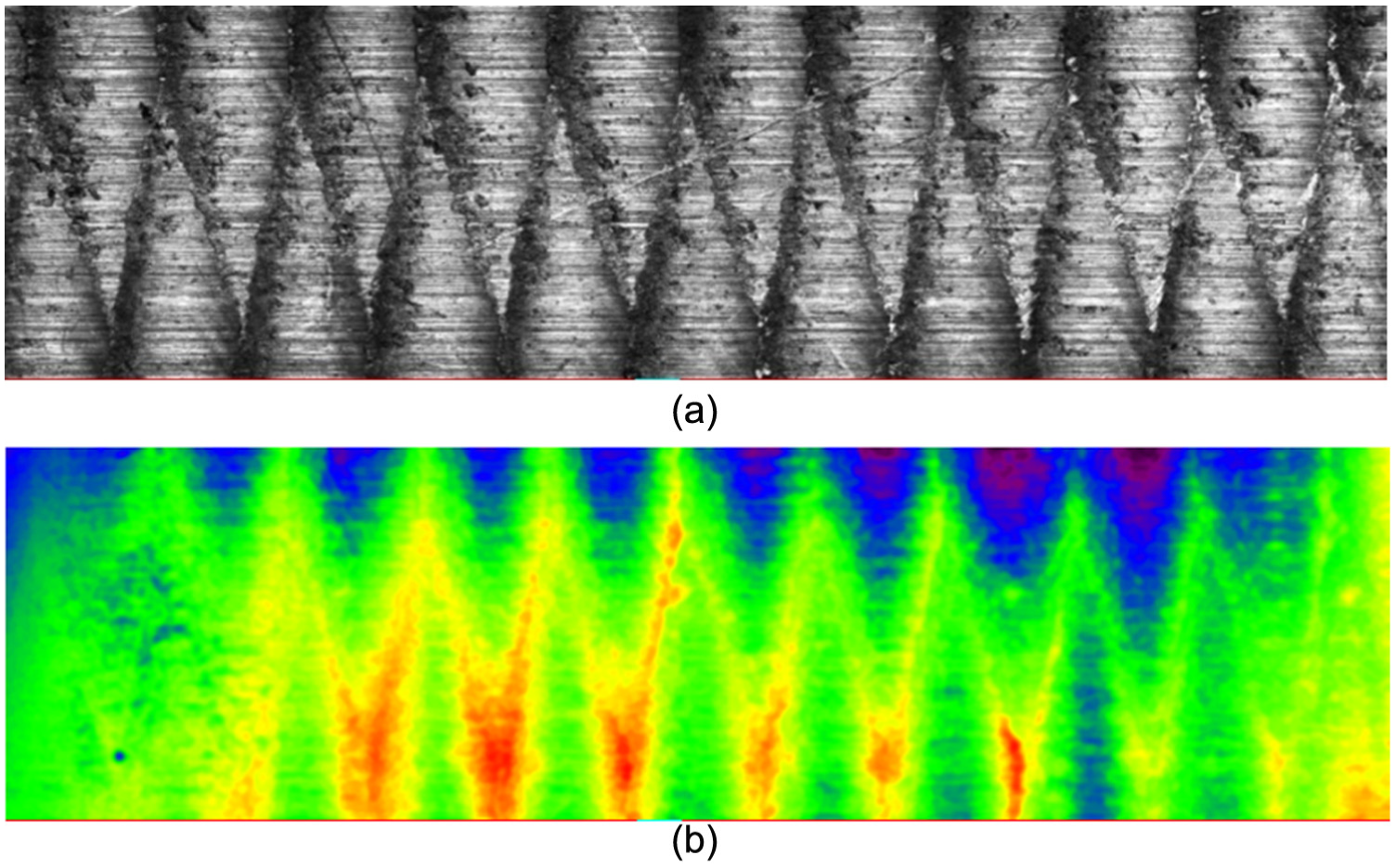
The microscopic image and surface topography of the machined surface are shown in Figure 11. Figure 11(a) is a microscopic photograph of the machined surface (4 mm × 1 mm) formed by a two-tooth cutting tool. Figure 11(b) shows the surface topography of that part. Figures 12(a) and (b) are parts of the machined surface (2 mm × 2 mm) formed by a four-tooth cutting tool. Figure 13 is the comparison of two surfaces machined with same tool rotation errors and different feed speeds. The results validate the surface model in section “Influence of tool rotation errors on tool tip movement” and the analysis in section “Machined surface quality.”
Machined surface of the two-tooth tool: (a) microscopic photograph and (b) surface topography.
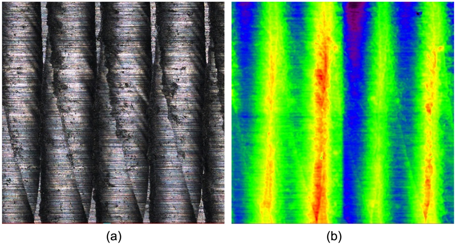
Machined surface of the four-tooth tool: (a) microscopic photographs and (b) surface topography.
Two surfaces machined with the same tool rotation errors and different feed speeds.
Conclusion
In this work, we studied the flank milling process with tool rotation error and deformation error. First, a tool teeth moving trajectory model influenced by tool rotation error was studied. Second, the effects of tool rotation error on cutting force were discussed. Third, experiments were conducted to detect tool rotation errors to validate the milling process model. Fourth, the relationship between tool rotation errors and surface topography was measured through the milling process model. The results show that tool runout error and tilt error have similar influence on surface topography and quality. Both of them caused extra surface roughness in the simulation case. The effect of tool rotation errors on surface topography decreases with increasing feed rates, and tool rotation error changed the machined surface frequency. As a result, the tool rotation error can be estimated by comparing PSDs for different surface frequencies.
Footnotes
Declaration of conflicting interests
The author(s) declared no potential conflicts of interest with respect to the research, authorship, and/or publication of this article.
Funding
The author(s) disclosed receipt of the following financial support for the research, authorship, and/or publication of this article: This research was supported by Science Fund for Creative Research Groups of National Natural Science Foundation of China (No. 51521064) and the National Natural Science Foundation of China (No. 51575484 and U1501248).