
Abstract
Tungsten carbide (WC) hard metals are universally used in industrial fields owing to their superior properties, and the machining accuracy of WC products is playing an important role in their service performance. However, how to achieve a balance between high accuracy and processing cost according to different applications is a key engineering issue. Thus, it is necessary to reveal the material removal characteristics of such difficult-to-cut hard metals. In this article, ultra-precision grinding characteristics of WC-Ni hard metals were investigated based on the wafer rotation grinding method using #120, #600, #2000, and #12000 diamond cup wheels as coarse, semi-finished, fine, and finish grinding wheels, respectively. A polished sample was taken for comparison. The optical surface profilers, scanning electron microscope, and atomic force microscope were employed for checking surface topographies, surface morphology, and cutting depth. An ultra-smooth and defect-free WC-Ni surface with less than 2 nm Ra and the average cutting depth of about 10 nm can be obtained using a #2000 diamond wheel, which can replace polishing and satisfy the requirements of most high-performance applications. This study provides useful observations for ultra-precision manufacturing of hard metal products.
Introduction
Tungsten carbide (WC) hard metals are fabricated from hard WC grains ranging in size from 0.01 to 20 μm mingling with a soft metallic binder content from 3 to 30 wt% under a sintering temperature of about 1400 °C. Excellent properties can be achieved with a combination of hardness, toughness, strength, erosion–corrosion, and wear resistance.1–3 WC hard metals display equivalent hardness but higher flexural strength and ductility compared to traditional ceramics. Conversely, they have lower ductility but higher strength and hardness with respect to metal alloys. Therefore, they are extensively suitable for a variety of industrial applications such as cutting tools, mining bits, sandblasting nozzles, molds, mechanical seals, and pump valves.4–6 Generally, hard metal products for mining and construction applications are subjected to intensive abrasive wear, high impact grade, and severe thermal and mechanical loading. 7 Hard metals for cutting tools are focused on their excellent wear resistance, high hardness, and flexural and compression strength.8,9 Hard metals used as molds and dies emphasize high hardness, high abrasion wear resistance, high corrosion resistance, longer life expectancy, high precision, and good quality. 10 In the past decades, about 67% hard metal products are used in cutting tools, near 20% in wood working and construction industries, and almost 13% in mining, oil drilling, or tunneling industries. 11 The performance of WC hard metals can be changed by adopting different binder materials according to specific applications. From the point of view of material constituents, Co has been mostly employed as the binder phase due to its excellent wettability and temperature-dependent solubility on WC, and it can also aid in sintering. However, Co resource is excessively depleted. 12 This stimulates researchers to find other alternative binders such as Ni, Fe, and Cr that still maintain superior properties to WC-based hard metals.13,14 Ni, for which the structure and properties are close to those of Co, has drawn increasing attention. It also has many distinct merits such as lower cost, higher temperature resistance and corrosion resistance, less environmental impact, and the ability to prevent carbide particle agglomeration.15–17 At present, many high-end industrial equipments are seeking high-performance core parts for providing safe operation and improving the entire system reliability. For instance, the 300-mm-diameter mechanical seals made of WC-Ni hard metals used in nuclear reactor coolant pumps are always working under the conditions of high temperature, high pressure, radioactive, and corrosive water. Such seals are considered as one of the most important parts, the durability and reliability of which will affect the operating status of the whole nuclear power station. Therefore, there are stricter and increasing machining requirements to ensure the surface roughness and dimensional accuracy of the workpiece to be limited within a certain extent.18–22
In recent years, researchers have made great efforts on searching techniques to machine WC hard metals. Lin and Su 23 executed lapping and electropolishing experiments for WC blocks. The lapping results indicated that the material removal rate and surface roughness value increased with using coarser abrasive grains, and a minimum surface roughness Ra of 0.13 μm could be obtained when the grain size was 4 μm after 2-h lapping. Material removal of electropolishing WC was close to Faraday’s law, and the surface roughness Ra was minimized to 0.8 μm at the optimal electropolishing time of 400 s. Kuppuswamy and Mubita 24 used electropolishing as an alternative to mechanical polishing for machining the cutting edge of WC ball nose end mills. The surface roughness Ra of about 0.3 µm was achieved, and the material removal amount was controlled within 10%–15% of the theoretical value. Hintze et al. 25 machined WC-Co cemented carbides by a polycrystalline diamond (PCD) milling tool and investigated the chip formation, cutting forces, tool wear, surface roughness, and integrity of the boundary zone by changing many parameters such as cutting edge chamfers, radial depths of cut, and cutting velocities. The surface roughness Ra was controlled within the submicron-to-micron scale. Liu et al. 26 investigated ductile chip formation by turning WC materials using cubic boron nitride (CBN) tools and demonstrated that there was a transition from ductile to brittle mode no matter whether conventional or ultrasonic vibration-assisted cutting was adopted. The critical value of cutting depth for transition in ultrasonic-vibration-assisted cutting was increased from 4.761 to 15.995 μm relative to the conventional way. Liu and Li 27 presented a theoretical and experimental study on ductile-regime cutting of WC using a CBN turning tool and found that the critical value changing the cutting mode from brittle to ductile was 2.114 μm. Moreover, although a defect-free surface can be obtained using the diamond tool of smaller tip radius, the tool wear was too severe to fabricate a large-size workpiece with a high form accuracy. Li et al. 28 developed a new method called inclined ultrasonic vibration cutting with a negative rake angle for single-point diamond turning WC hard metals in the ductile regime, and the values of surface roughness Ra were decreased from 2.55–8.85 nm to 1.82–6.2 nm compared to conventional ultrasonic vibration turning. Zhang et al. 29 ground the WC-Co carbides using 20-mm-diameter wheels, for which the mesh size is #325 and #1500 with a rotational speed of 20,000 r/min to perform coarse and fine grinding. The surface roughnesses Ra of about 20 and 5 nm were achieved under the conditions of 1 and 0.5 μm cutting depths, respectively. Qian et al. 30 conducted comparative experiments of grinding two nickel-based superalloy K4125 and Inconel 718. It is found that there are more defects such as smearing, redeposited chips, or striations, and they are easier to adhere to the ground surface of K4125 causing the surface roughness higher than that of Inconel 718. Yin et al. 31 reported ultra-precision grinding of 10-mm-diameter WC spherical mirrors using a #1000 metal-bond diamond wheel and gained the peak-to-valley (PV) value of 83–104 nm, while the surface roughness Ra is less than 5 nm. Guo et al. 32 executed single-grit scratching experiments for fabricating binderless WC microstructured surfaces and found that the average three-dimensional surface roughness (SRa) was 60–78 nm. The critical cutting depth of such material calculated was 156 nm. Zhou et al. 33 established a finite element model to characterize the material removal mechanism of particulate-reinforced titanium matrix composites in high-speed grinding and found that brittle and plastic removal occurs simultaneously during the material removal process. In addition, grinding based on electrolytic in-process dressing (ELID) has been recognized as an effective finishing technology to achieve ductile-regime machining in most engineering materials.34,35 However, it requires extra electrolysis set-ups, metal-bonded wheel, and electrolyte. Especially, the electrolyte might induce environmental pollution. Mueller et al. 36 analyzed the material removal mechanisms of two-phase brittle materials WC-Co by means of single-grain cutting tests. It was found that the ductile material removal behavior was observed at low grain engagement depths and the material removal behavior switched from ductile to brittle mode as the grain engagement depth increased. Overall, each machining method has its advantages and disadvantages. Lapping and polishing are successful in producing ultra-smooth surfaces and generally considered as the final machining process, although the efficiency is not quite satisfactory and lacks the ability to control the form accuracy of the workpiece. Milling, as a promising machining method, still has to afford a potential high risk of tool failure. Turning is essentially a finishing process of high speed, low feed, and low cutting depth that is easy to realize ductile material removal, while tool wear may cause dimensional, geometric form, and surface roughness error degradation. Grinding still has the problem of tool wear, but it has drawn considerable attention and is regarded as one of the most appropriate methods to process hard metals from the statistics of the literature.
Most of the previous studies focused on machining WC-Co hard metals which are gradually replaced by other alternatives. Correspondingly, technical details of the material removal mechanism should be further investigated. In this study, ultra-precision grinding experiments were performed to demonstrate the material removal characteristics of WC-Ni hard metals by testing the surface roughness, surface morphology, and cutting depth. A wafer polished by free abrasives was selected to make a contrast. The results may provide significant references to ultra-precision grinding products made of hard metals.
Materials and methods
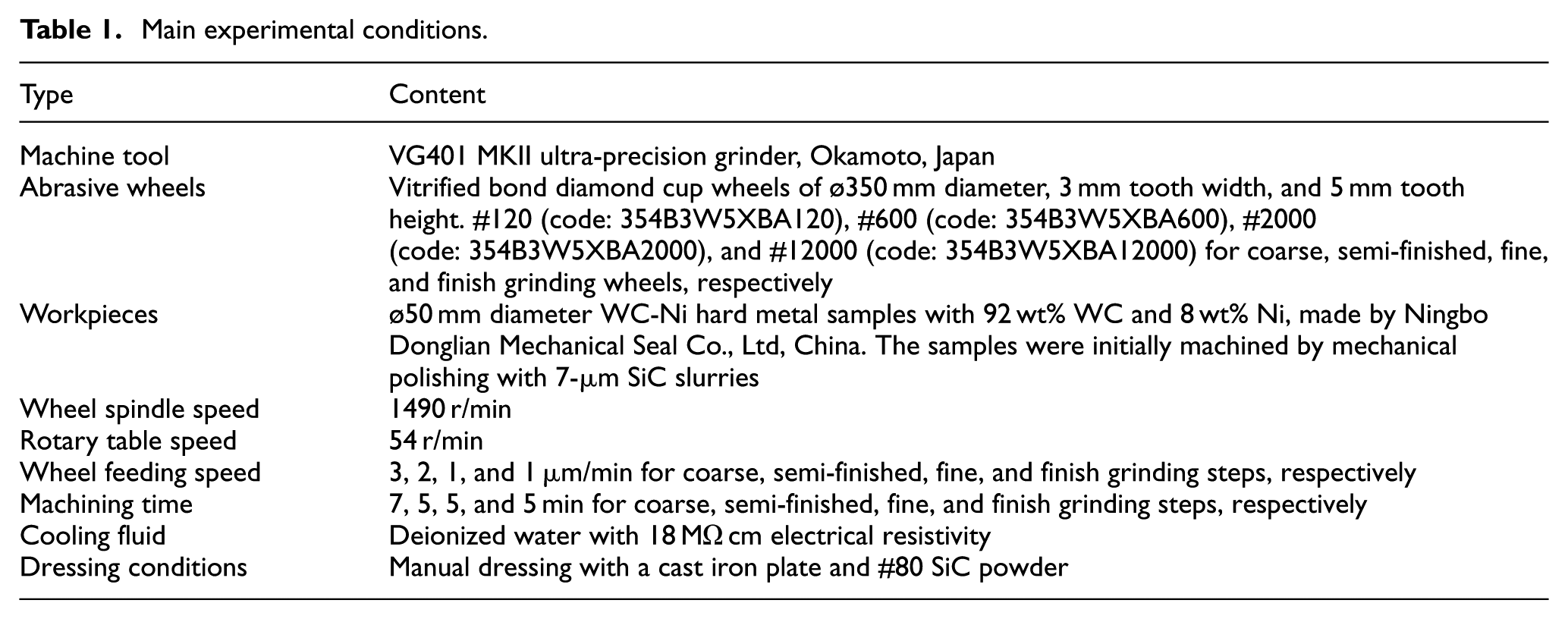
The experiments were carried out based on the wafer rotation grinding method using cup wheel. The on-site photograph is shown in Figure 1. Two principal components are the wheel spindle and the rotary table, and both of them are supported by air bearings that can ensure the axial and radial runout less than 0.05 μm. The teeth of the cup wheel pass through the workpiece center, and the two spindles can rotate independently. The feeding direction of the wheel spindle is vertical to the workpiece surface, and the minimal feeding speed is 1 μm/min. A specially designed stationary and detachable fixture was used for fastening the samples which were first glued on the steel plate with wax. All the samples were cooled and washed with deionized water that there was no contamination left on the ground surface. Detailed experimental conditions are shown in Table 1.
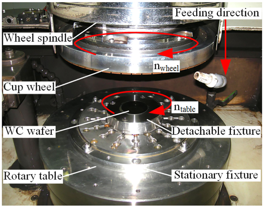
On-site photograph of ultra-precision grinding experiments.
Main experimental conditions.
Results and discussion
Surface topographies
The ground and polished surface topographies were measured by an optical surface profiler (NewView 5022; Zygo Corp., USA) and the scanning areas were 71 × 51 μm2 which are shown in Figure 2 and the values of Ra, root mean square (RMS), and PV are shown in Figure 3. It can be found that the basic rule is that the values of Ra, RMS, and PV become smaller by adopting finer grinding wheels. Semi-finished grinding with a #600 diamond wheel can obtain a surface roughness of one half than coarse grinding with a #120 diamond wheel, and the surface roughness values will be further decreased using a #2000 diamond wheel. However, the influence of such improvement seems unapparent even when a #12000 diamond wheel is used. In contrast, the polished sample surface displays a different status that the Ra and RMS values fall between semi-finished and fine grinding but close to the latter one, while the PV value reaches up to 364 nm. The surface quality achieved by fine grinding is better than that by mechanical polishing, even though the grinding wheel and the free abrasives have the same grain size. This is caused by the different material removal mechanism between fixed and free abrasive machining, and there exist more deep scratches on the polished surface than coarse grinding. Therefore, in order to obtain high-quality surface for high-performance products, grinding owns its specific superiority which can maintain relatively uniform surface quality in accordance with the grain size selected.
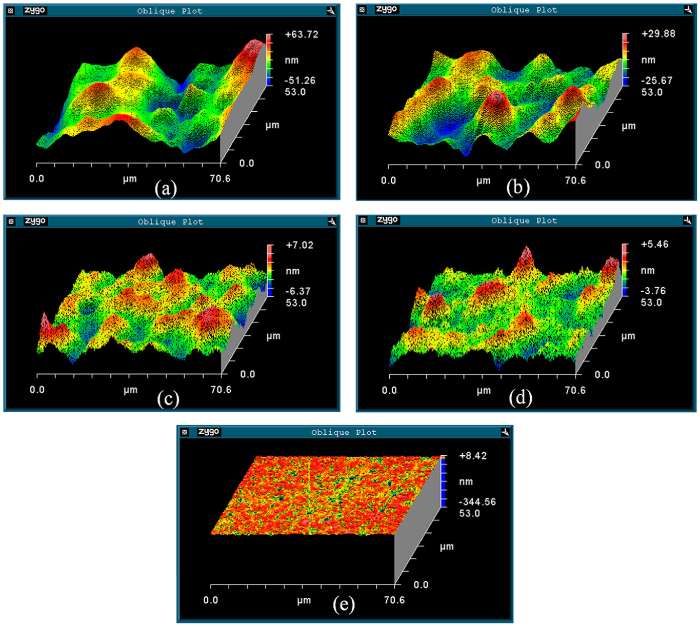
Surface topographies of WC-Ni wafers: (a) coarse grinding, (b) semi-finished grinding, (c) fine grinding, (d) finish grinding, and (e) polished.
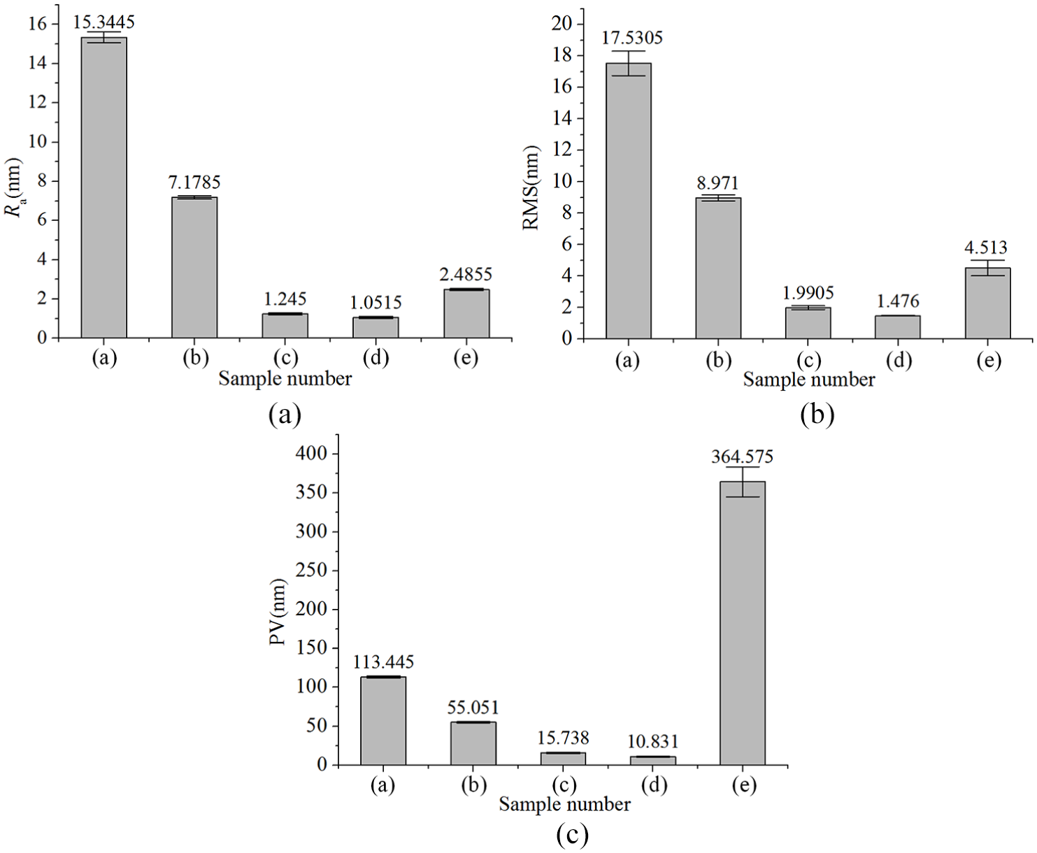
Ra, RMS, and PV values: (a) coarse grinding, (b) semi-finished grinding, (c) fine grinding, (d) finish grinding, and (e) polished.
Surface morphology
A scanning electron microscope (SEM; SUPRA 55; Carl Zeiss, Germany) was employed to observe the microscopic surface morphology of the WC samples. In Figure 4(a), the whole ground surface shows mainly ductile material removal characteristics. The width difference among the ground grooves is apparent. There are a lot of deep and wide grooves that produce dominating damages, and shallow and narrow grooves display absolutely ductile material removal appearance. Since many WC particles have been plucked out and rolled over the sample surface, serious damages of pits and deep grooves are generated. Meanwhile, the built-up edges or plastic materials have piled up along the grooves. It can be found that the relatively soft metal Ni is smeared out over the surface with the pulverized WC particles that some bulges stack on the ground surface. In other words, the bulges are formed by two different phenomena: flow-out of the material from grooves due to plastic deformation and move-out of the material from grooves due to brittle fracture. Thus, the SEM examinations indicate that the material removal of WC-Ni is conducted by the combination of ductile flow and brittle fracture, while the former is dominant. The pull-out of the WC particles, pile-up of the built-up edges, deep grooves, and misdistribution of plastic materials cause the ground surface look rough. Moreover, there exist minor brittle material removal characteristics on the ground surface, as a number of chips and debris are generated along the grinding scratches or near the pulverized WC particles. The smearing of Ni mixed with the grinding chips and debris forms a covering layer on the sample surface, which makes the boundaries between the WC particles and Ni binder difficult to be identified.
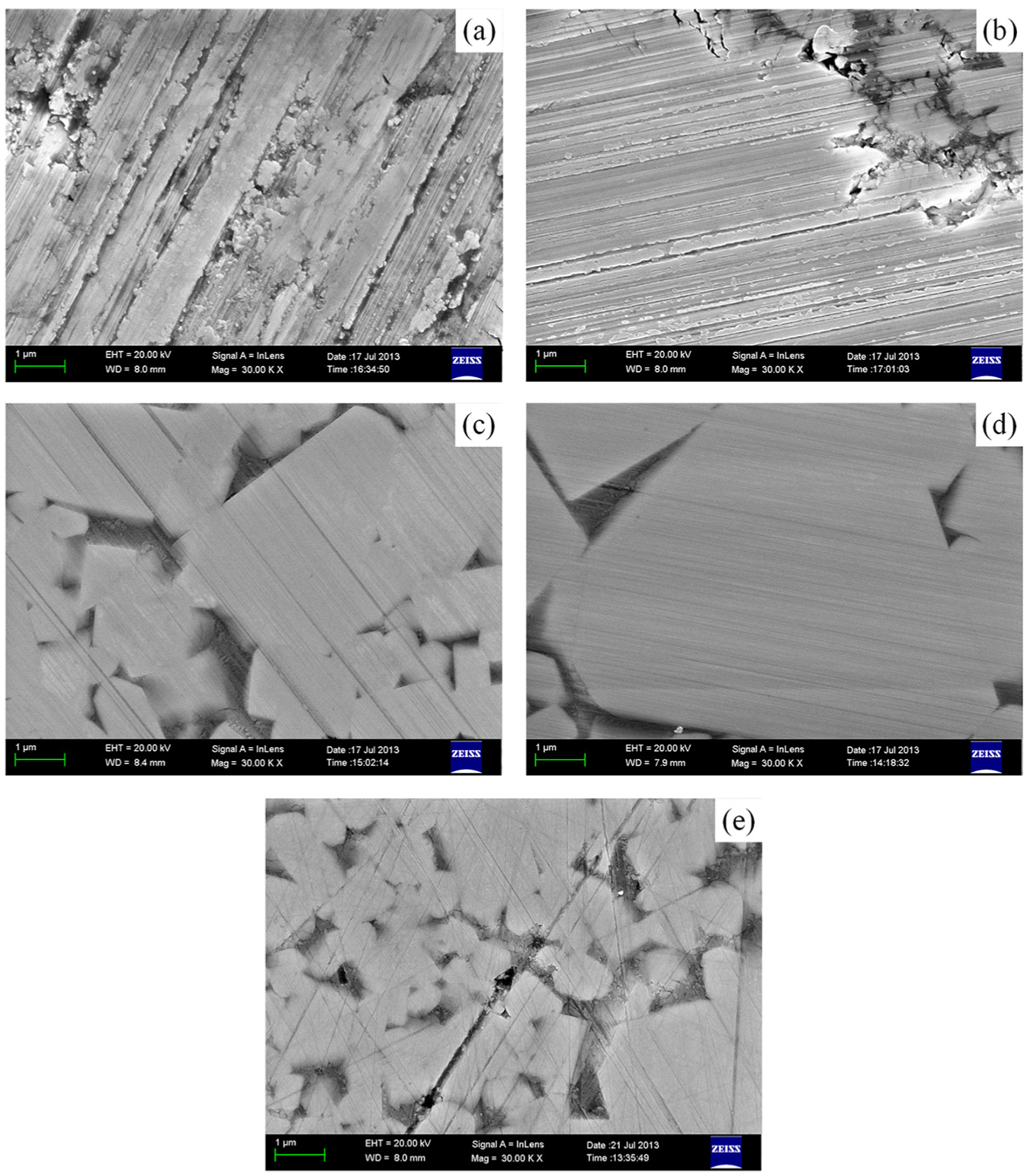
SEM images of WC-Ni wafers: (a) coarse grinding, (b) semi-finished grinding, (c) fine grinding, (d) finish grinding, and (e) polished.
In Figure 4(b), the ground grooves are more uniform as the dimension of the built-up edges becomes smaller. A few WC particles are cracked or plucked out leaving micro-pits at the phase boundaries. A small number of WC particles are pulverized and flaked away, and the soft Ni binder is smeared over the surface and partly removed together with the WC grains and fragments. The surface topography is almost completely ground under ductile regime in appearance except for a few cracks. The number of pile-ups near the grooves is limited. The SEM image shows that the materials are prevailingly removed by plowing and pushed sideways by the diamond abrasives. Pull-out and pulverization of WC particles can be found but they just occur in localized areas. Cracks of the WC particles are mostly observed near the boundaries, as WC particles are cracked and pulverized by the high applied stresses of the diamond abrasives. It is also shown that a part of the WC particles are plastically deformed by the compressive stresses in front of the abrasive grains. This kind of compressive stresses can generate a series of cracks which are generally perpendicular to the grinding direction. The grinding grooves became even and displayed typical ductile material removal characteristics. The bulges created in coarse grinding have disappeared because the WC material is plowed by the diamond abrasives plastically and piled up continuously besides the grinding grooves. Less chips and debris can be discovered on the ground surface. The depth and width of an individual grinding groove are uniform along the grinding direction, though they are different from the others. The main damages involve cracks and pull-out of the WC particles. Meanwhile, the soft binder Ni between WC particles undergoes severe deformation during grinding. The deformed Ni is extruded by the compressive stress applied by abrasives of the diamond wheel, which might be caused by the wheel topography, abrasive accumulation, or admixture of large abrasives. Therefore, semi-finished grinding of WC-Ni hard metals with a #600 diamond wheel cannot produce a defect-free surface.
In Figure 4(c), the ground WC surface is smooth enough, and the boundaries between the WC particles and the binder Ni are easy to identify. Just a few relatively deep grooves can be observed and the materials are removed by plastic flow. There are no pile-ups left because all the materials are swept away by the grinding wheel. Meanwhile, no grinding-induced cracks and fractures are observed on the sample surface. Wrinkles appear where the binder Ni is concentrated. The reason is deduced that grinding is performed by geometrically undefined cutting edges of the abrasive grains. Therefore, many grains implement negative rake angle cutting. When the abrasive grains contact the workpiece surface, the binder Ni will be squashed under high pressures and the wrinkles are produced.
In Figure 4(d), there exist no damages and the vaguely discernible grinding grooves distribute uniformly on the whole ground surface. All the materials are removed in the ductile regime, and no deep grooves and pile-ups are found on the ground surface. Therefore, an ultra-smooth and defect-free surface can be produced when the WC wafer is ground with a #12000 diamond wheel. Although all the processing parameters are the same and there is an obvious dimension difference in diamond grains between fine and finish grinding, the final ground surface quality is improved slightly. The result demonstrates that selecting a grinding wheel with a finer grain size will not be helpful for further decreasing the surface roughness as expected after all the materials have already been removed in the ductile regime. Nonetheless, it is noticeable that finish grinding requires frequent dressing to sharpen the wheel, and it is a time-consuming and costly work.
In Figure 4(e), the surface quality of the polished wafer seems close to that ground by a #2000 diamond wheel, but there exist many defects. The interlaced scratches are generated by random motions of free abrasives. The deep pits are considered as pull-out of the WC particles or probably the pores left during the sintering process, and the deep scratches are caused by larger abrasive grains or roll-over of the large WC particles cracked by the abrasives. There are just extremely small chips and debris on the inner edges of the grinding grooves occasionally. The soft binder Ni between WC particles is liable to undergo severe compressive stress by the free abrasives. Overall, the grooves on the polished surface are not as uniform as those produced by ultra-precision grinding and their width and depth change markedly, which leads to deterioration of the surface quality. Apparently, polishing by free abrasives has limited ability to achieve the same surface roughness level compared with ultra-precision grinding.
Consequently, the SEM images indicate that the WC-Ni hard metal samples display mainly ductile material removal characteristics when the feeding speed is set to 3 μm/min even when a #120 diamond wheel is used. But during the coarse grinding step the surface layer damages are apparent and there exist several deep pits and a number of cracks. If the WC-Ni products are used in top-level applications such as mechanical seals of nuclear reactor coolant pumps, the surface roughness of which is limited within 5 nm, 22 finish grinding with a #12000 diamond wheel is recommended. Otherwise, it is unnecessary to pursue higher grinding accuracy because it is inefficient and costly, while grinding with a #2000 diamond wheel is financial and sufficient.
Cutting depth
Nanoscale topographic surfaces were tested using an atomic force microscope (AFM; XE-200; PSIA Corp, Korea). The scanning area was limited to 20 × 20 μm2. Taking machining accuracy into consideration, the fine grinding, finish grinding, and polished samples were selected to test and make a contrast. In Figure 5(a), it can be found that the average cutting depth of the abrasive grains is about 10 nm. Deep grooves for which the maximal values reach 12 nm are also present on the ground surface. In Figure 5(b), the average cutting depth is about 6 nm, and the maximal value displayed is about 14 nm. Although the maximal cutting depth measured is larger than that ground with #2000 diamond wheel, a dominant difference is that it is generated on the binder Ni area but not on the WC particle surface. In Figure 5(c), the average cutting depth is about 10 nm and the maximal value displayed is about 20 nm. Previous studies interpreted that the key factor to determine hard materials removed in the ductile regime is the critical cutting depth, dc, which can be calculated by the following equation37,38
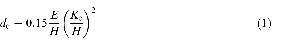
where E is the elastic modulus, H is the hardness, and Kc is the fracture toughness. Meanwhile, Liu et al. 26 and Guo et al. 32 reported that the critical value of ductile cutting WC hard metals is approximately between 1.5 and 2 μm due to different material ratios of the hard metal to the binder. Wu et al. 39 reported grinding of WC surface using a microstructured coarse-grained diamond wheel, and the critical cutting depth calculated is 156 nm, which is consistent with that referred above. However, the equation used is limited to single-phase and brittle materials. The dc value will become smaller when it is used for evaluating multi-phase materials. Klocke et al. 40 presented a method to analyze the material removal behavior transition of WC-Co hard metals from ductile to brittle regime by single-grain cutting tests based on a parameter, hcu,crit, called the critical chip thickness. The critical chip thickness values are about 3, 4, and 10 μm for WC-Co hard metals with 4, 6, and 12 wt% Co. It can be concluded that the critical chip thickness for WC-Ni hard metals will be more than 3 μm considering the component percentage of Ni because the critical cutting depth for single-phase hard materials must be smaller than that of multi-phase materials with a soft binder. In this study, experiments were carried out based on the wafer rotation grinding method. If f is the wheel spindle feeding speed and n is the rotational speed of the rotary table, the actual cutting depth, da, can be calculated by the following equation
AFM micrographs of WC-Ni wafers: (a) fine grinding, (b) finish grinding, and (c) polished.
The actual cutting depths from coarse to finish grinding calculated are about 56, 37, 19, and 19 nm, respectively. Apparently, materials are primarily removed in the ductile regime even using a #120 diamond wheel. Furthermore, abrasive grain size not only affects surface roughness but also governs the material removal rate and tool wear rate.41,42 When the abrasive grain size is of the same order of magnitude as the carbide size, the wear mechanism will be changed that the abrasive grains can interact with the carbides and matrix phase separately. The wear rate will increase as the WC grain size decreases on condition that the binder phase volume fraction is fixed. 43 Noticeably, choosing diamond wheels with a proper grain size is undoubtedly an important factor that influences the machining surface quality, efficiency, and cost. The grain size of the diamond wheel, dg, can be calculated by the following equation44,45
where M is the mesh size of a diamond wheel. As a consequence, the dg values of the #120, #600, #2000, and #12000 diamond wheels are about 127, 25, 7.6, and 1.3 μm, respectively. Theoretically, the WC-Ni hard metals should be ground in the ductile regime completely as the actual cutting depth is less than the critical value. Nonetheless, brittle material removal characteristics appeared during coarse and semi-finished grinding steps. This is because the cutting depth is not the only factor affecting the ductile-regime machining. Rake angle and edge radius of the diamond grains also have remarkable influence. Especially, as a difficult-to-cut material, WC possesses a hardness value close to the diamond grain, which leads to rapid wear of the diamond grains. Therefore, the diamond grains cannot intrude into the WC-Ni hard metals effectively and the compressive stresses applied to the workpiece surface increase sharply after a certain grinding period. Cracks and pulverization are generated subsequently. Consequently, it needs taking material properties, abrasive properties, and processing parameters into account to achieve a balance between high accuracy and processing cost according to different applications.
Conclusion
Ultra-precision grinding characteristics of WC-Ni hard metals are demonstrated in this article, and the materials are mainly removed in the ductile regime when the #120, #600, #2000, and #12000 diamond wheels are chosen as coarse, semi-finished, fine, and finish grinding wheels, for which the feeding speeds are set to 3, 2, 1, and 1 μm/min, respectively.
In the coarse and semi-finished grinding steps, there are still many chips and debris generated on the ground surface which indicates that brittle material removal characteristics also exist during the grinding process. The cracks and pulverized WC particles cause the ground surface quality to deteriorate.
An ultra-smooth and defect-free WC-Ni surface with less than 2 nm Ra and the average cutting depth of about 10 nm can be achieved using a #2000 diamond wheel, which can satisfy the requirements of most high-performance applications. Moreover, the #12000 diamond wheel can be rarely adopted to grind high-end parts with extremely strict surface quality demands because it is time-consuming and costly.
Compared with mechanical polishing, ultra-precision grinding can produce a high-quality surface with uniform grinding grooves since the cutting depth can be controlled precisely, and machining with fixed abrasives owns enhanced capability to control the form accuracy. Therefore, ultra-precision grinding can replace mechanical polishing as the final machining process under certain situations.
Footnotes
Declaration of conflicting interests
The author(s) declared no potential conflicts of interest with respect to the research, authorship, and/or publication of this article.
Funding
The author(s) disclosed receipt of the following financial support for the research, authorship, and/or publication of this article: This work was supported by Sub-project of Major Science and Technology Project of Shanxi Province (No. 183060169S) and Science and Technology Project of Taiyuan Science and Technology Bureau (No. 183060073K).