
Abstract
Based on the Rayleigh–Ritz method, this article proposes an indicator to quantify the stiffness of a conical cutter for flank milling of impellers. Its validity is verified by the finite element analysis. A mathematical model is then developed to optimize the geometry of the conical cutter. The objective is to improve the stiffness of the cutter. Three kinds of geometric constraints are considered. First, the ball end of the cutter should be tangential to the hub surface. Second, the cutter should be interference-free with the adjacent blade. Finally, the machining error should satisfy the precision requirements. All these geometric constraints are characterized by the signed point-to-surface distance function. Based on the differential property of the distance function, a sequential linear programming method is applied to obtain the optimal geometry of the cutter along with the tool path. Simulation results confirm the effectiveness of the proposed model and algorithm.
Introduction
Fans, compressors and impellers are the main components of turbo-machinery. High-efficiency machining of these bladed components has drawn much attention in academia and industry. At present, blades are mainly manufactured by five-axis computer numerical control (CNC) milling with two distinct methods: point milling and flank milling. Flank milling comparatively outweighs point milling in several respects: higher material removal rate, elimination of hand finish, improvement of machining precision, and so on. Therefore, flank milling has been widely applied in manufacturing turbo-machinery components.
Most previous works on tool path generation for flank milling focused on reducing the machining error. Liu 1 presented a double point offset (DPO) method to generate a tool path for flank milling of ruled surfaces. Tsay and Her 2 derived an analytical model to account for undercutting incurred in flank milling with cylindrical cutters and then the model was used to minimize the machining errors. Li et al. 3 proposed a tool path generation method based on the angle-based flattening parameterization technique. Bedi et al. 4 proposed a tool path positioning method to position the cutter which is tangent to the two boundary curves of the ruled surface. Bera et al. 5 studied the variation of surface error during milling of thin-walled tubular geometries under varying milling conditions. Li et al. 6 developed a method to minimize the error between the given surface and the machined surface. Recently, several global methods have been proposed to optimize tool paths by approximating the tool envelope surface to the design surface. By deforming the two curves that defined the tool axis trajectory, Lartigue et al. 7 reduced the geometric deviation between the design surface and the envelope surface, but an approximate distance was employed to simplify the computation. Based on the error propagation principle, Gong et al. 8 formulated the problem as least squares fitting of the tool envelope surface to the point cloud on the offset surface of the design surface. Later, it was extended to optimize tool path for flank milling with a generic cutter based on the approximation of the tool envelope surface. 9 On the basis of the cutter swept envelope as the envelope of the two-parameter family of spheres and following the minimum zone criterion, Zhu et al. 10 recently developed a model and algorithm for tool path planning from the perspective of surface approximation.
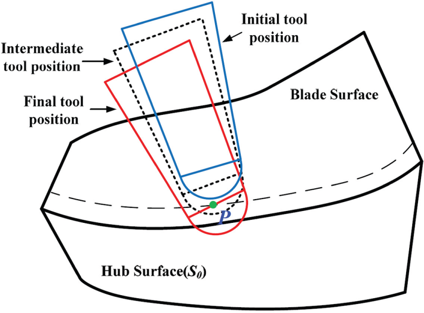
In real machining processes, there are three fundamental requirements for the five-axis flank milling. First, with the increasing demand for performance designs, components with complex geometries and surfaces are required to be manufactured in tight tolerance; therefore, the machining error should satisfy the precision requirement. Second, for widely utilized ball-end cutters, the ball end of the cutter should be tangential to the hub surface to avoid interference. 11 Third, the cutter should be interference-free with the adjacent blade. As the distance between two adjacent blade surfaces is relatively small in some centrifugal impellers, interference between the cutter and adjacent blade may occur if an unsuitable cutter is chosen, as shown in Figure 1. In order to generate interference tool paths, some strategies have been proposed. Tsay et al. 12 developed an algorithm to generate tool paths with global interference checking for five-axis point milling of turbo-machinery components. The interference between the surface of the work-piece and the cutter can be detected based on the projected distance. Lee and Suh 13 presented an interference-free tool path planning method to machine twisted ruled surfaces.

Interference of the cutter with the adjacent blade in flank milling.
Increasing the stiffness of the cutter can effectively improve the rigidity of the whole cutting system and consequently reduces the deflection and vibration in the milling process. Two measures are usually taken to increase the stiffness of the cutter. The first way is to shorten the tool length, which can reduce the deflection and vibration, and result in better accuracy and surface quality in machining. 14 An efficient computation algorithm of optimal tool length for five-axis mold and die machining was presented in Cho et al. 15 They computed the minimum feasible tool length via slight modification of tool orientation at the selected numerical control (NC) blocks where tool-length reduction was required. Bi et al. 14 generated collision-free and smooth tool orientations along with a safe and shortest tool length (SSTL). The SSTL was determined by optimizing the tool orientations under the constraints of global collision avoidance and tool orientation smoothness. The second way is to optimize the cutter shape. Chaves-Jacob et al. 16 developed an approach that optimized the tool shape for a given trajectory surface pair to reduce the interferences. Monies et al. 17 introduced an algorithm to calculate the error between the conical cutter and the work-piece so as to determine the optimal cutter shape (cone radius and angle). Zheng et al. 18 recently formulated a constrained nonlinear programming to optimize the cutter size considering both local and global interferences. However, the cutter shape was not completely optimized except the cutter radius in this article. In order to avoid the interference between the cutter and the hub surface, Zheng et al. presented a method that the boundary was aligned between the design surface and the envelope surface with a flat cutter. However, for the widely used ball-end cutters, the ball end should be tangential to the hub surface at each tool position. Based on the distance function, Zhu et al. 19 developed a model and algorithm for simultaneous optimization of the tool path and shape for five-axis flank milling. However, geometric constraints are not considered.
In this article, an indicator that quantifies the stiffness of a conical cutter is proposed. Then our previous work on tool path optimization10,20 is extended to tool shape optimization with the aim to improve the stiffness of the cutter under complex geometric constraints. The remainder of this article is organized as follows: In section “Geometric foundations,” the geometric foundation of this article is briefly introduced. The swept envelope of a conical cutter is modeled as a sphere-swept surface, and an approach is presented to compute the signed distance between the swept surface and a point in space without constructing the swept surface itself. In section “Stiffness of a conical cutter,” an indicator quantified the stiffness of a conical cutter is presented. In section “Geometric constraints,” three kinds of geometric constraints are analyzed and described by the distance function. In section “Model and algorithm for optimization of cutter geometry,” the problem of cutter shape optimization is formulated as a constrained optimization problem. A number of classical numerical optimization algorithms can be applied to solve it because the derivatives of the involved objective function and constraint functions are all available. Examples are presented in section “Examples.” Conclusions are given in section “Conclusion.”
Geometric foundations
Representation of cutter swept envelope as sphere-swept surface
Consider a conical cutter shown in Figure 2. The effective cutter surface can be represented as the envelope surface of a one-parameter family of spheres. The center
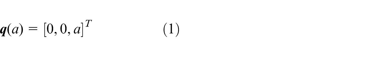
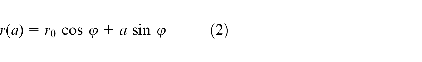
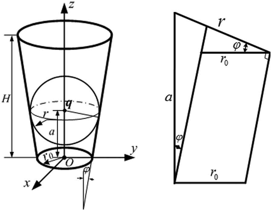
Geometry of a conical cutter.
where
As illustrated in Figure 3, the tool motion is usually represented by two guiding curves
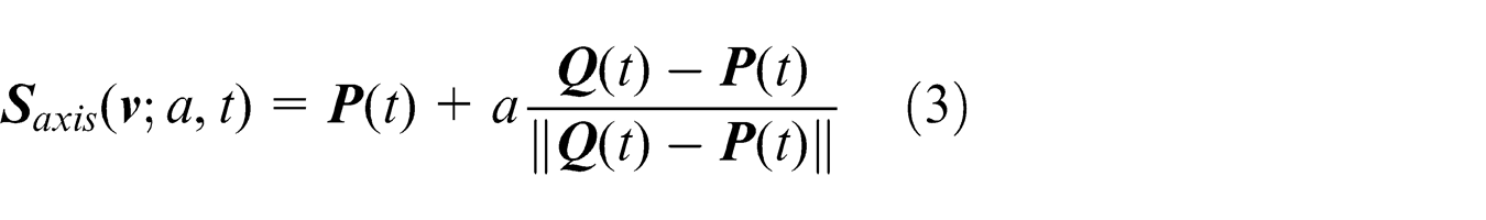
Tool axis trajectory surface defined by two guiding curves.
where
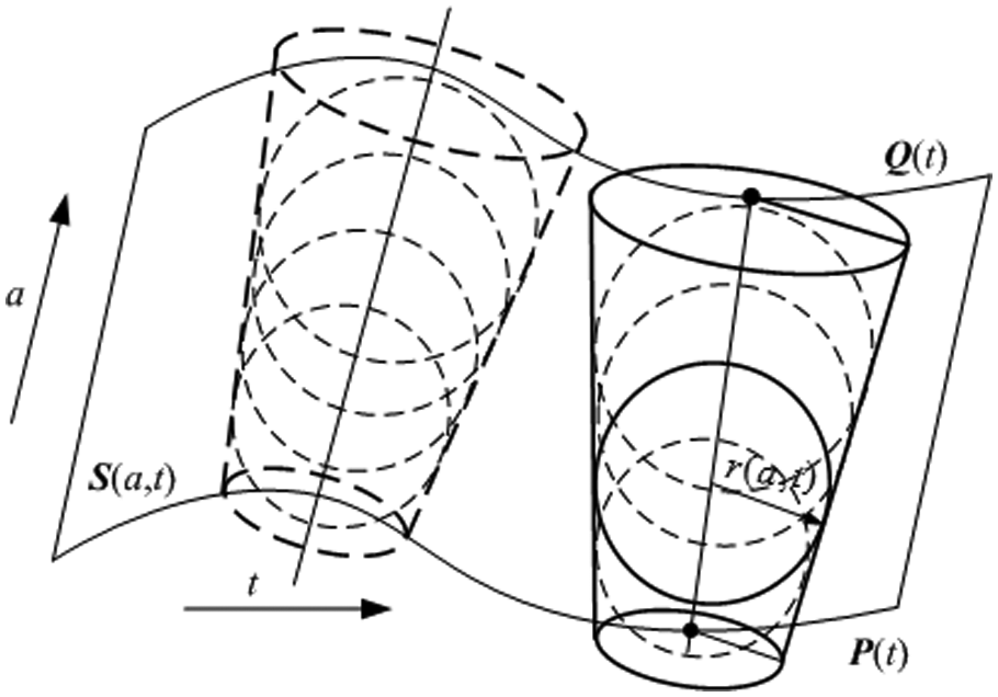
As stated above, the cutter surface can be modeled as the envelope surface of a one-parameter family of spheres. Therefore, a two-parameter family of spheres would be generated if the cutter undergoes a one-parameter spatial motion. The center
where
Computation of the signed distance from a point to the cutter swept envelope
For NC machining simulation and verification, distance computation between the cutter swept surface and the part model surface is of great importance. Because a complex surface can always be approximated by a point cloud, here the computation of the signed distance between the cutter swept surface and a point is of concern. According to our previous work, 10 the point to surface distance can be computed by minimizing the distance between the point and a sphere in the sphere congruence, as shown in Figure 4. Hence, we have
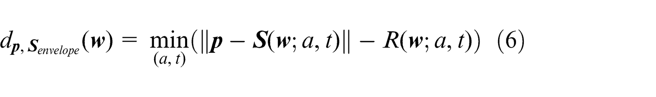
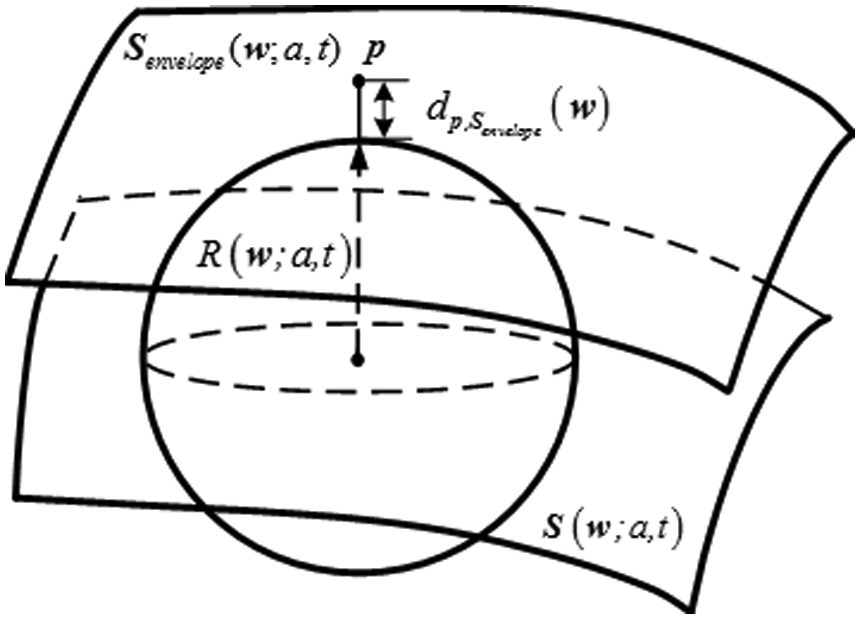
Point to envelope surface distance.
The minimum value is obtained by solving the following system of equations
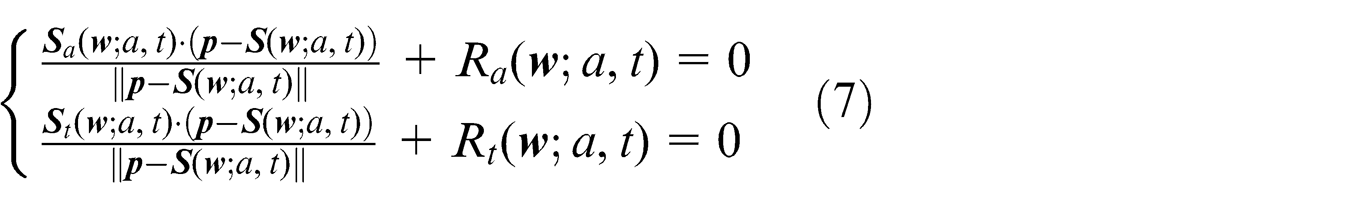
The signed distance between the point and the swept envelope surface is positive if the point lies on the exterior of the swept volume and negative if the point lies in the interior of the swept volume. Although the signed distance must be computed by an iterative approach, its first-order differential increment with respect to the differential deformations of both the cutter surface and the cutter axis trajectory surface has analytical expression
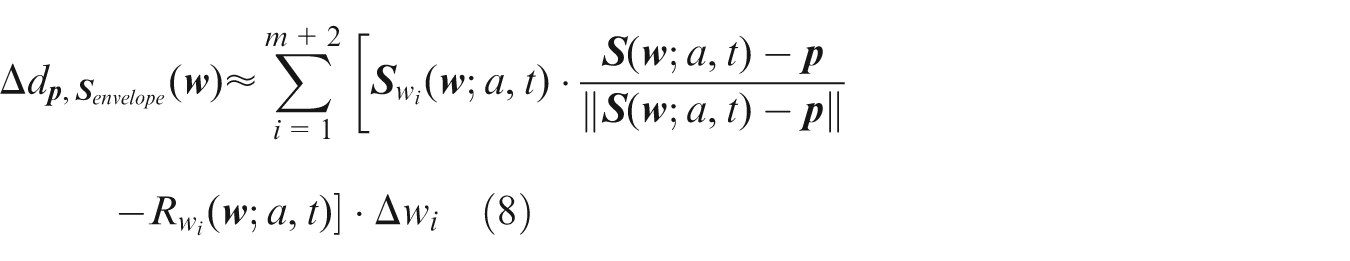
It characterizes the normal deformation of the cutter envelope surface under the changes of both the cutter trajectory and shape.
Stiffness of a conical cutter
The cutter is modeled as a cantilever beam with one end fixed by a chuck. It is assumed that a concentrated load F is applied at the end of the cutter, as shown in Figure 5(a). The cutter is deflected, and the maximum elastic deformation
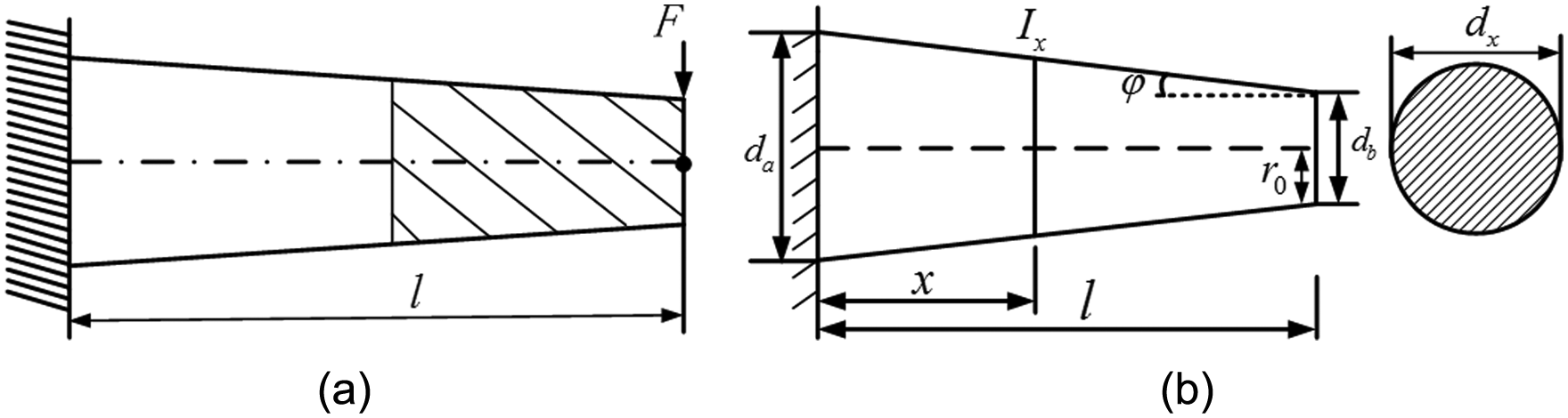
Conical cutter deflection model: (a) a conical cutter with a concentrated load F at the end and (b) a conical cutter’s characteristics.
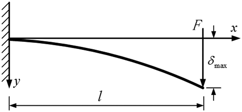
Deflection of a cantilever beam.
It is difficult to get the analytical expression of the deflection curve
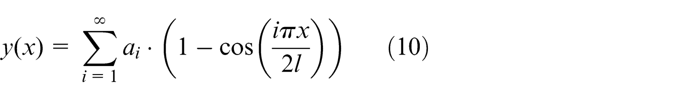
where
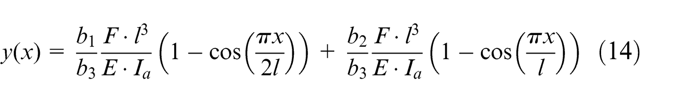
To ease the calculation, only a finite number of terms in equation (10) is kept. Therefore, the following expression is used as an approximate deflection curve of the cutter
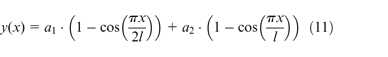
The potential energy of a beam is defined as the sum of the strain energy and the work potential. The work potential is the negative of the work done by the external force acting on the beam, which is the multiplier of the force and the displacement of the point of application of the force. The potential energy functional of the cutter is therefore
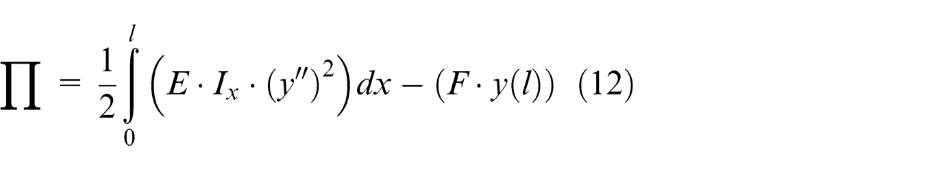
where E is Young’s modulus for the cutter material, and
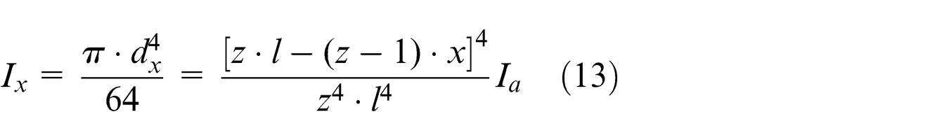
where
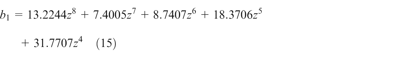
Minimizing the potential energy functional Π with respect to the coefficients
where
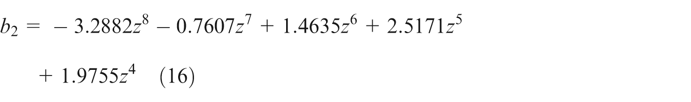
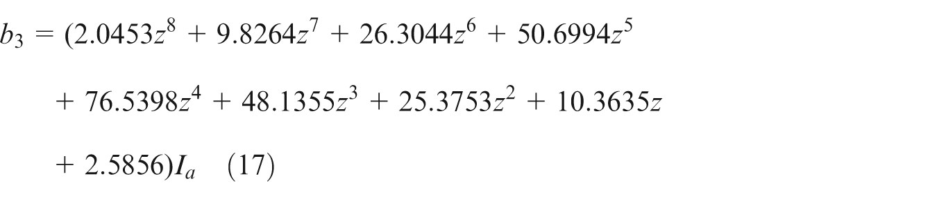
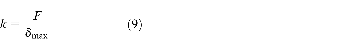
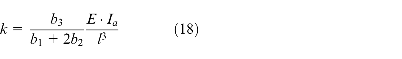
Following equation (9), the stiffness of the conical cutter has the expression
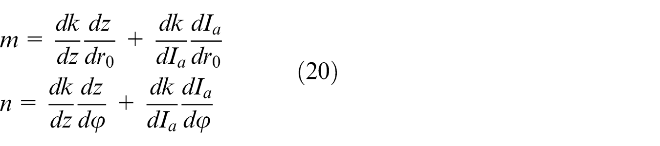
The first-order differential increment of the stiffness

where
The formulas of
To test the accuracy of the approximate solution, the finite element analysis with ANSYS software is employed to calculate the static deflection of the cutter. The geometric parameters of the cutter are chosen as: radius of bottom circle
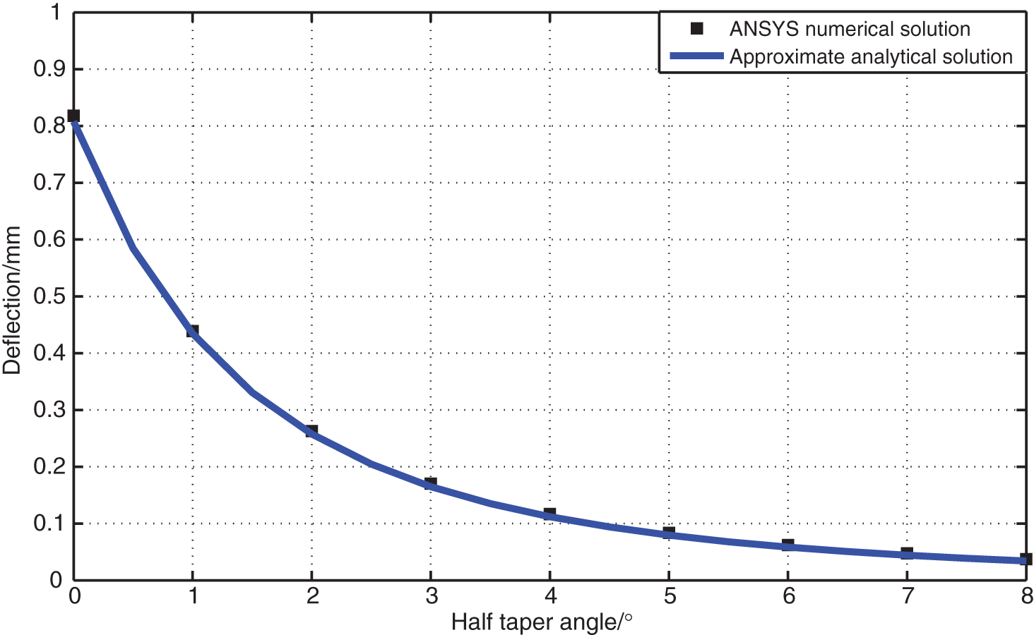
Approximate analytical solutions versus the ANSYS numerical solutions.
Geometric constraints
Three kinds of geometric constraints should be considered when machine the impellers. First, the ball end of the cutter should be tangential to the hub surface. Second, the cutter should be interference-free with the adjacent blade. Finally, the machining error should be smaller than the tolerance. These geometric constraints all can be described by the distance function.
Constraint of machining accuracy
From the geometric viewpoint, machining error is the deviation between the design surface and cutter envelope surface. As shown in Figure 8, there are two separate envelope surfaces swept by the side of the cutter. The surface that generates the machined surface is called the effective envelope surface
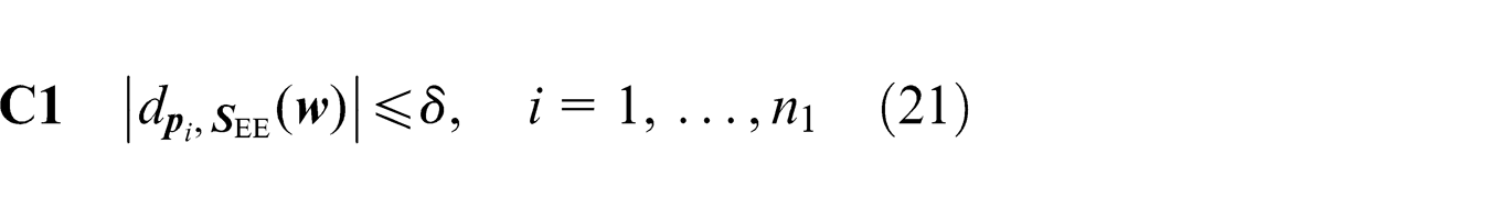
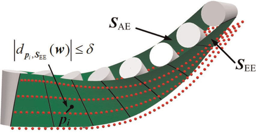
Constraint of machining accuracy.
Constraint of tangent the cutter with the hub
When a ball-end cutter is used, the ball end of the cutter should be tangential to the hub surface at each cutter location (CL). As a result, the blade surface and the smooth fillet are machined in a single pass. As illustrated in Figure 9,
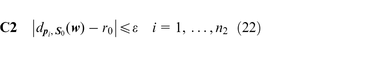
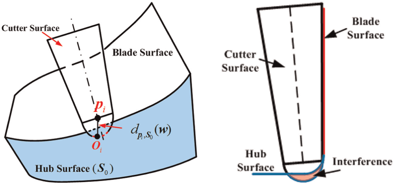
Constraint of tangent the cutter with the hub.
where ε is the prescribed geometric tolerance.
Constraint of collision avoidance of the cutter with the adjacent blade
One of the major problems outlined in five-axis flank milling of impellers is the interference between the cutter and the adjacent blade, which is usually caused by an unsuitable cutter size, as shown in Figure 1. For a set of data points
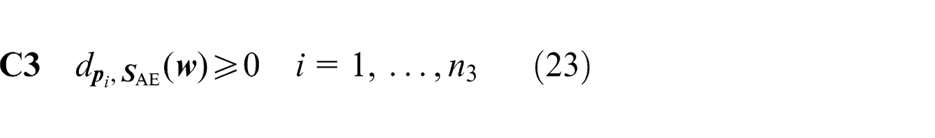
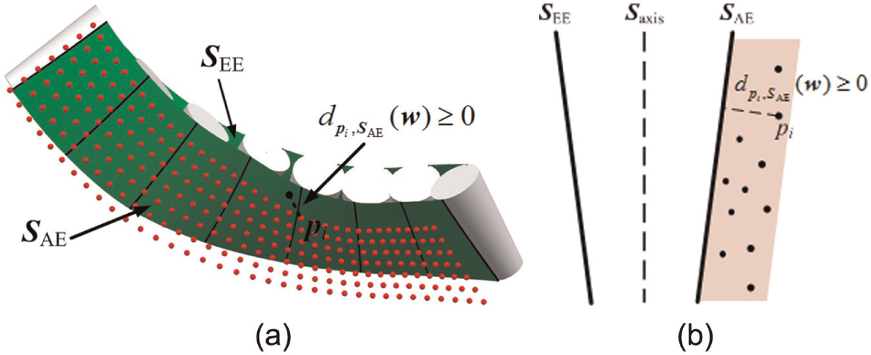
Constraint of collision avoidance of the cutter with the adjacent blade: (a) Three-dimensional sketch map and (b) Two-dimensional sketch map.
Model and algorithm for optimization of cutter geometry
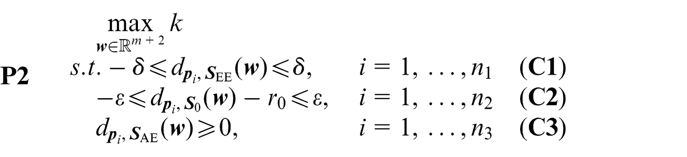
According to the analysis presented in sections “Stiffness of a conical cutter” and “Geometric constraints,” we propose the following model for optimal design of tool path and shape considering stiffness and multi-constraint. The objective is to improve tool stiffness. The geometric constraints are to meet the machining accuracy and interference-free requirements
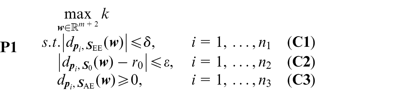
This is a nondifferentiable constrained optimization problem. It can be equivalently reformulated as the following differentiable constrained optimization problem
This optimization problem can be readily solved because the derivatives of the involved objective function and constraint functions are all available. A number of classical numerical optimization algorithms can be applied.
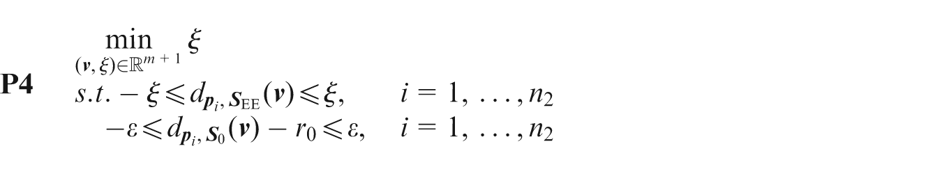
The optimal cutter bottom radius and half taper angle are normally fractional numbers. We can choose a suitable cutter from the cutter series with the bottom radius and half taper angle a little smaller than the optimal ones. Then, the optimal tool path can be generated by solving the following constrained Minimax problem
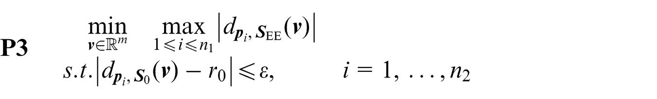
or equivalently
As shown in Figure 11, an initial tool position is determined using the method by Bedi et al.
4
But the ball end is usually not tangential to the hub surface. The ball-end center can be adjusted with the idea of dichotomy as proposed by Tang et al.
23
until the ball end is tangential to the hub surface (see the constraint in equation (22)). In the adjustment process, the cutter should meet the tangential requirements at each moving step as described in Bedi et al.
4
In this way, a number of discrete CLs can be calculated. The required initial tool axis trajectory surface is then generated by interpolating all these cutter axes. The method of sequential linear programming (SLP), which has been successfully applied to many practical nonlinear constrained optimization problems, is utilized to solve problem
Basic idea of computing the tool path.
Let
The linearized objective function is equivalent to
The main steps of the algorithm for determining the optimal geometry of a conical tool considering stiffness and geometric constraints are summarized as follows.
Algorithm (tool geometry optimization)
Step 0:
Set
Compute
Step1:
Solve the linear programming problem
Update
Compute
If
Examples
In order to demonstrate the validity of the proposed method, we give examples of flank milling of free-form impeller blades. As illustrated in Figure 12, the centrifugal impeller has 30 blades. Two cutters are applied. One is a ball-end cylindrical cutter, and its initial radius r
0 is chosen as 3.75 mm. The other is a ball-end conical cutter, and its initial bottom radius r
0 and half taper angle
Centrifugal impeller and blade surface.
The ball-end center of the cutter can be determined with the dichotomy method, and the CL can be calculated using the methods in Bedi et al. 4 and Tang et al. 23 Thirty tool axes are generated as the initial CLs, and the initial tool axis trajectory surface is obtained with the interpolation method.
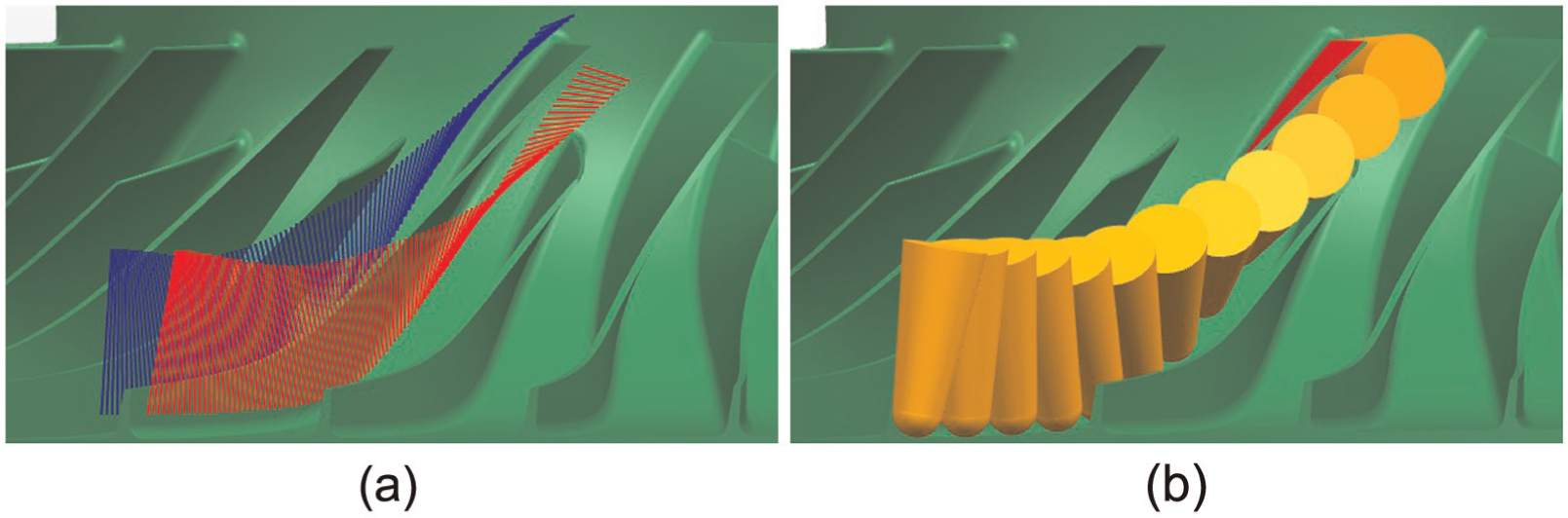
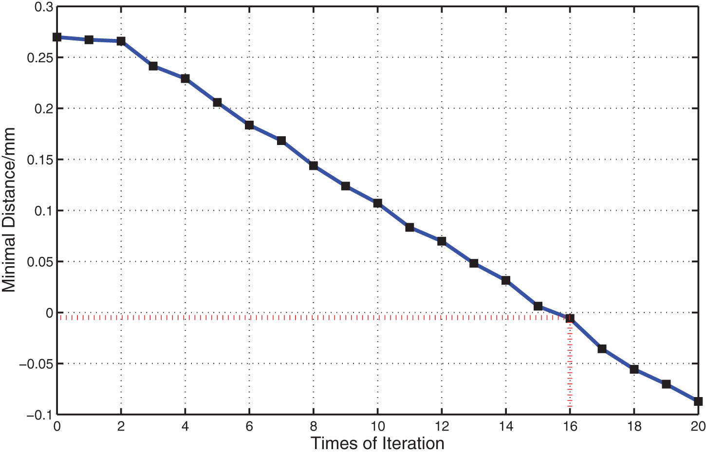
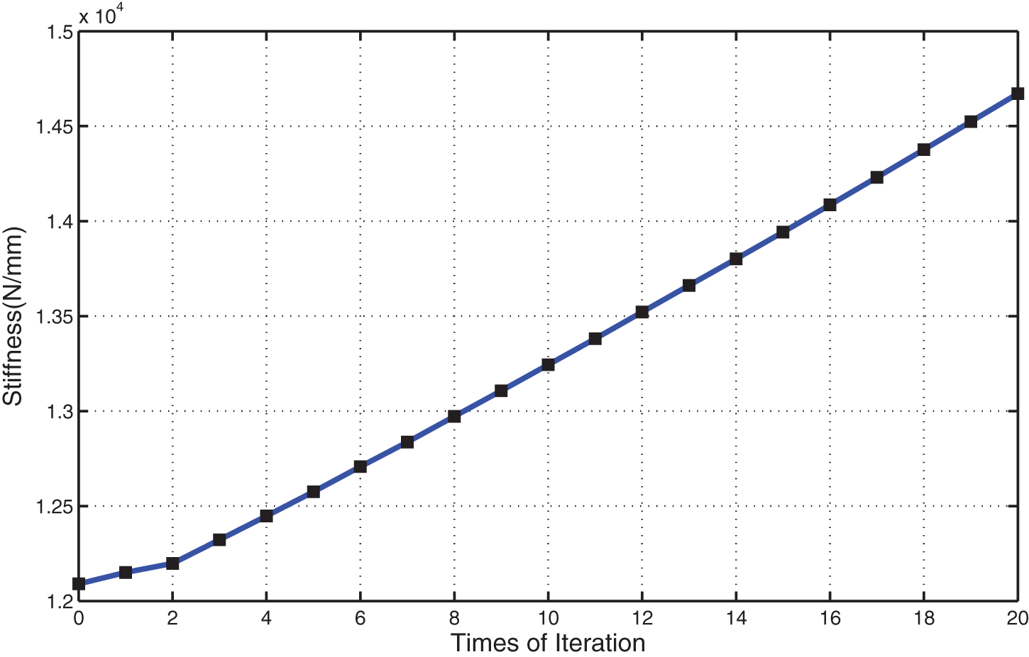
When the conical cutter is applied, the initial undercut and overcut are 0.0256 and 0.00754 mm, respectively. The initial tool path is shown in Figure 13. The SLP method is applied to solve the constraint optimization problem. The convergence process is depicted in Figures 14–17. As shown in Figures 15 and 16, the interference of the cutter with the adjacent blade occurs when the cutter bottom radius is 3.14 mm and half taper angle is

Initial tool path for conical cutter.
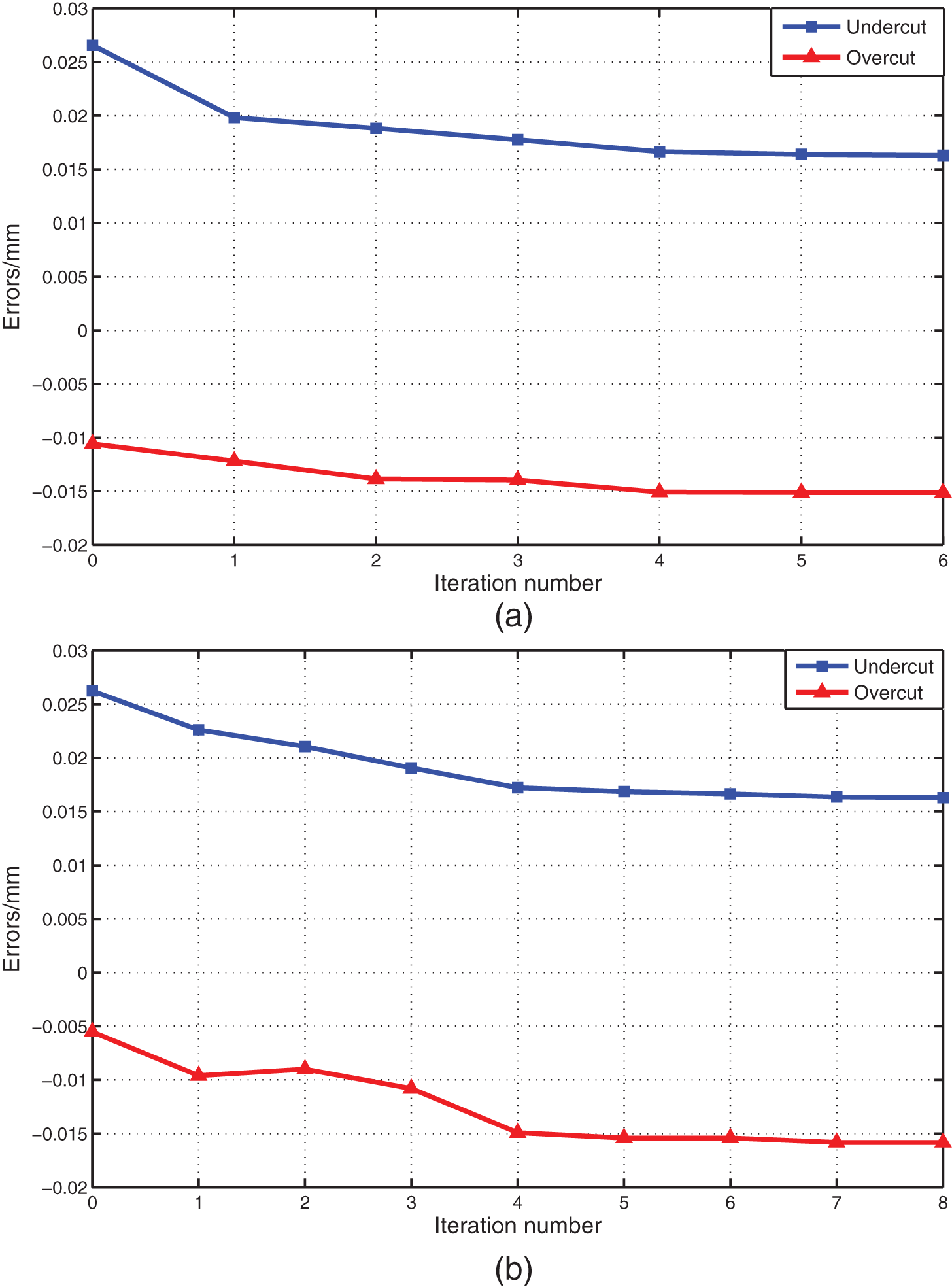
Geometric errors obtained in each iteration.
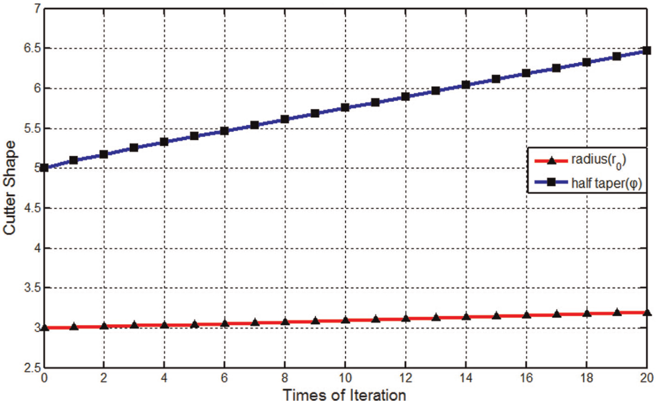
Cutter shape obtained in each iteration.
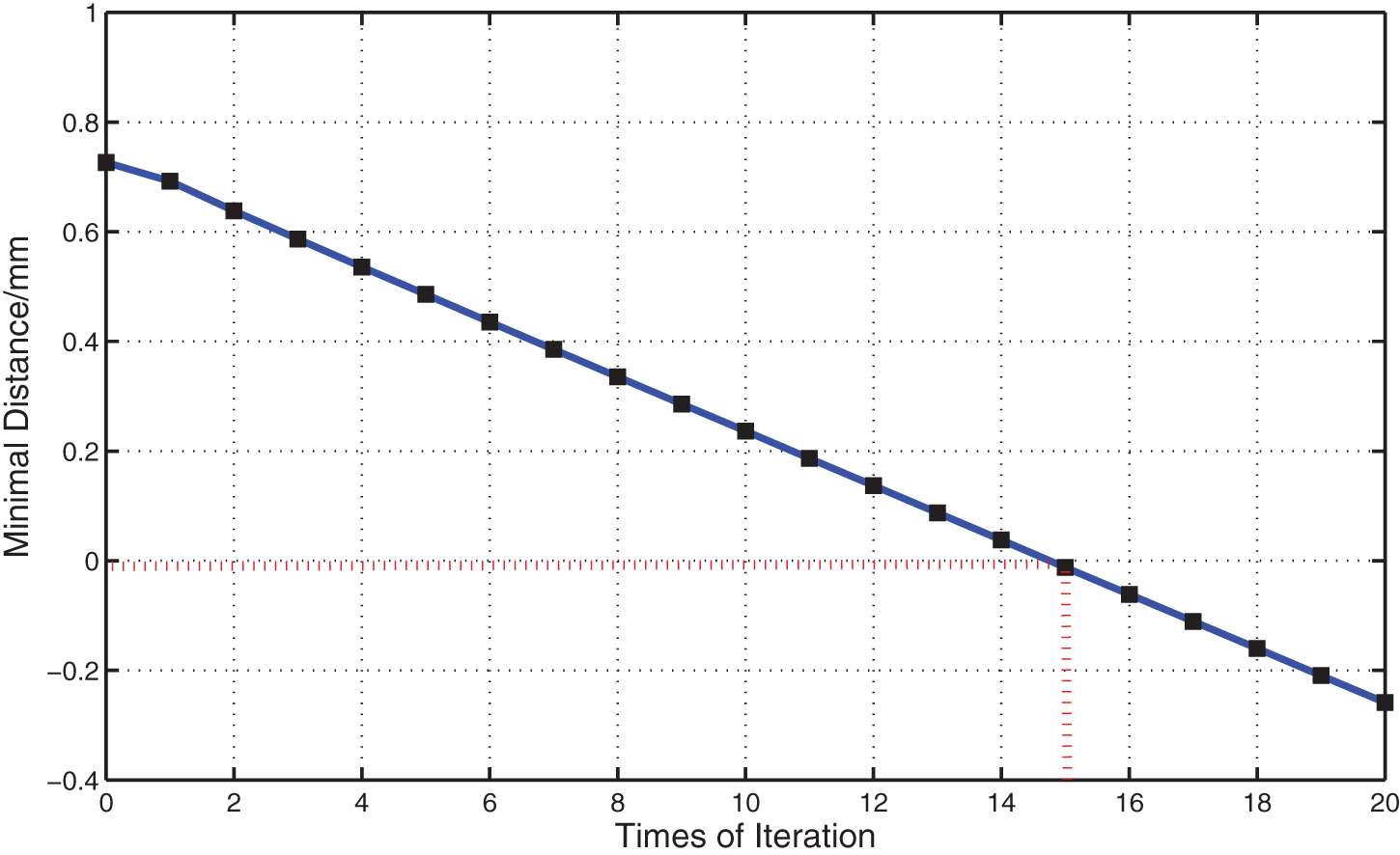
Minimal distance from the design surface to
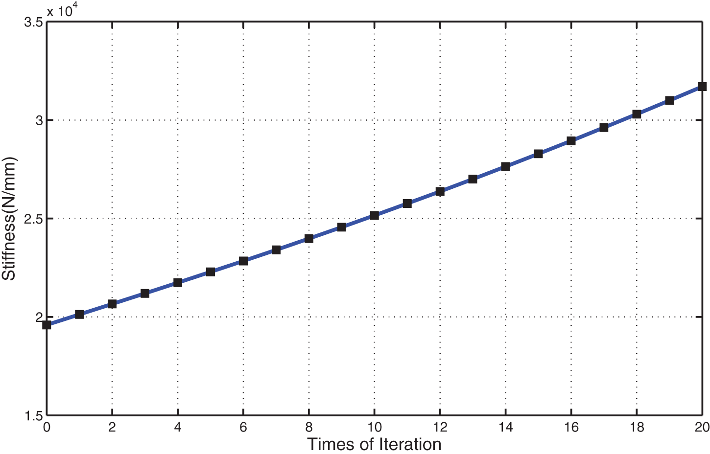
Stiffness of the conical cutter in each iteration.
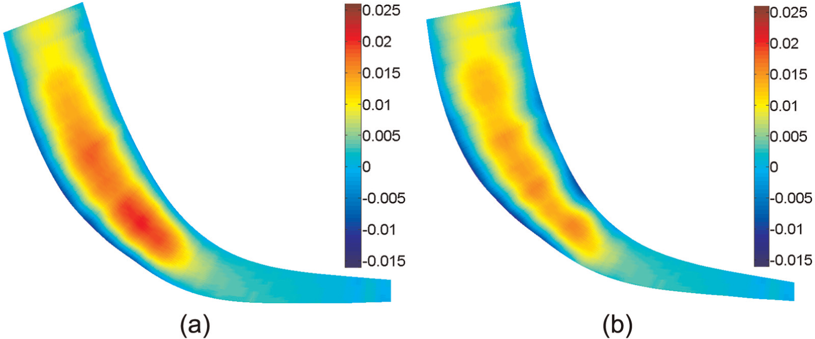
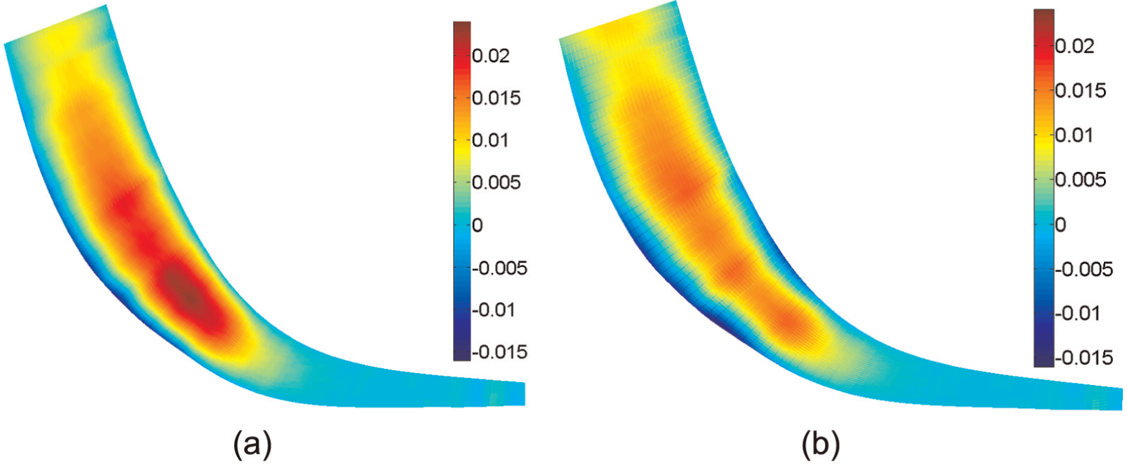
Distribution of the geometric errors of the machined surface (a) before optimization and (b) after optimization.
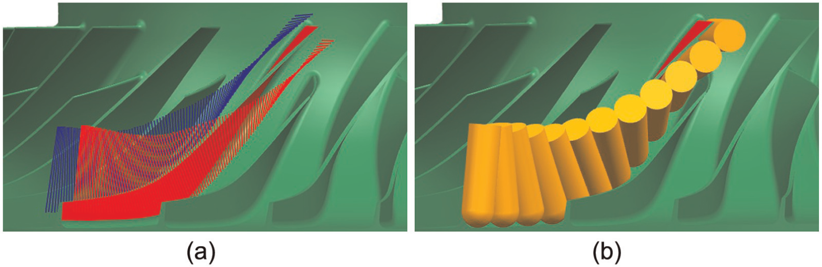
Optimal CLs for an impeller blade: (a) tool axis vectors and (b) tool profiles.
Convergences of the Minimax algorithm under different initial solutions: (a) Bedi et al.’s method and (b) Chiou’s method.
The computational results for the cylindrical cutter are obtained in a similar way and are shown in Figures 21–25. The interference occurs when the cutter radius is greater than 3.89 mm. Therefore, a cylindrical cutter with a radius of 3.75 mm is selected as the optimal cutter. Its stiffness is

Initial tool path for cylindrical cutter.
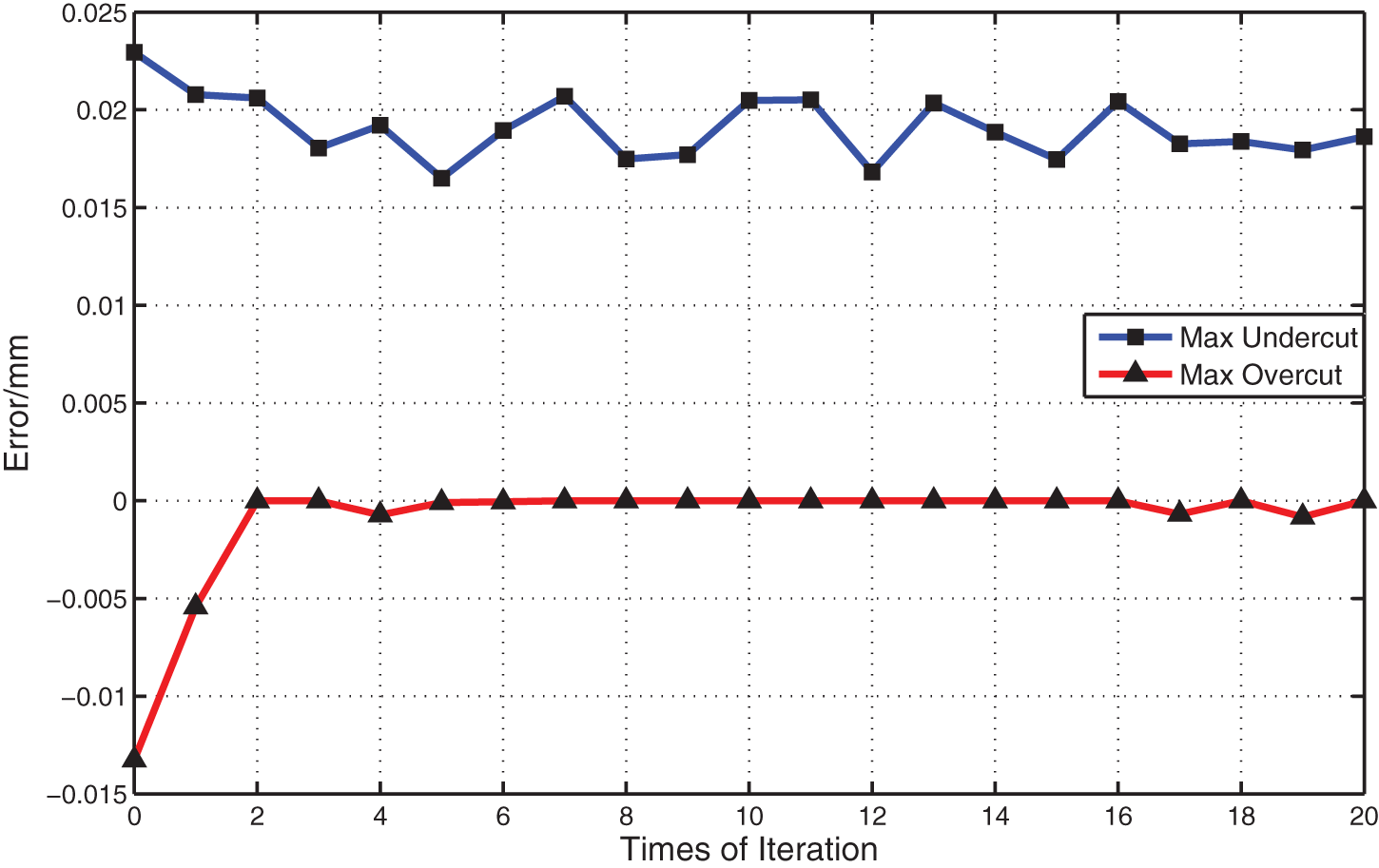
Geometric errors obtained in each iteration.
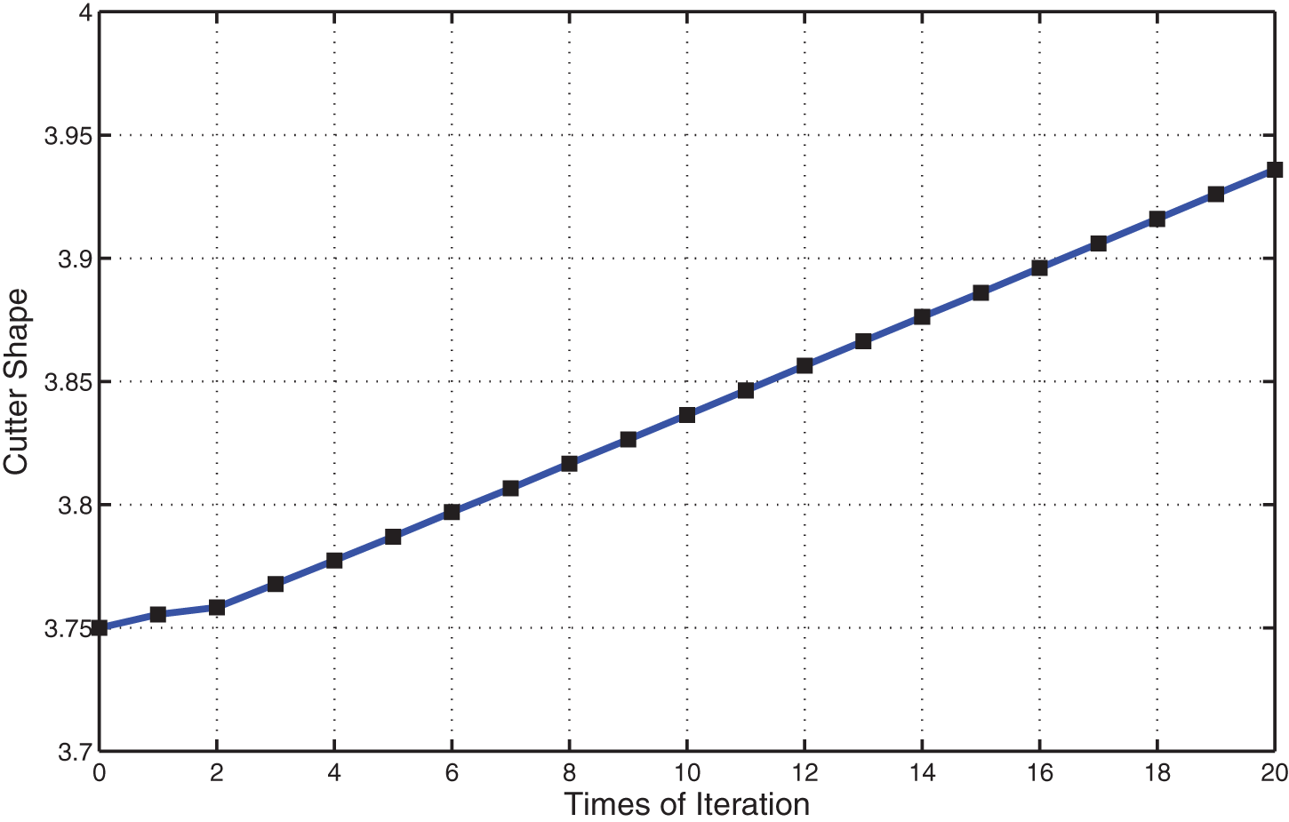
Cutter radius obtained in each iteration.
Minimal distance from the design surface to
Stiffness of the cylinder cutter in each iteration.
Distribution of the geometric errors of the machined surface (a) before optimization and (b) after optimization.
Optimal CLs for an impeller blade: (a) tool axis vectors and (b) tool profiles.
It is seen that the stiffness of the optimal conical cutter is twice as large as that of the optimal cylindrical cutter while the resulting maximal undercut and overcut almost keep unchanging. Thus, the present optimization approach benefits greatly the application of conical cutter to flank milling of impellers with complex blade shape and confined space between two adjacent blades.
Conclusion
Using the Rayleigh–Ritz method, an indicator is proposed to quantify the stiffness of a conical cutter. Then, based on our previous works on sphere-swept representation of cutter envelope surface and point-to-surface distance function, the model and algorithm for optimizing the geometry of the conical cutter for five-axis flank milling of impellers are developed. The objective is to improve the stiffness of the cutter. Three kinds of constraints are taken into account. Examples show that with this optimization approach, the stiffness of the conical cutter is doubled compared with that of the cylindrical cutter while the resulting machining error almost keeps unchanging. The approach applies to flank milling of impellers with complex blade shape and confined space between two adjacent blades. The work in this article lies in the field of computer-aided manufacture (CAM). From the obtained tool path to the actual machining, a great deal of topics should be taken into account, such as the post-processing, the feed rate scheduling and the machining dynamics. Attention is less paid to the smoothness of the tool path in this article. When the smoothness of the tool path is taken into account, a comprehensive tool path optimization model considering multi-objective, tool stiffness and tool path smoothness, is required. This will be developed in our future work.
Footnotes
Appendix 1
The formulas of
where
Declaration of Conflicting Interests
The author(s) declared no potential conflicts of interest with respect to the research, authorship, and/or publication of this article.
Funding
The author(s) disclosed receipt of the following financial support for the research, authorship, and/or publication of this article: This work was partially supported by the National Natural Science Foundation of China under grant no. 51325502, the National Key Basic Research Program under grant no. 2011CB706804, and the Science & Technology Commission of Shanghai Municipality under grant no. 13JC1408400.