
Abstract
High-speed machining provides an efficient approach for machining Inconel 718 with high quality and high efficiency. For high-speed milling of Inconel 718 curved surface, the geometrical characteristics are changing continuously leading to a sharp fluctuation of cutting force, which will aggravate the tool wear. As the wear mechanism of coated cutting tool is seriously affected by the cutting tool geometrical parameters, suitable geometrical parameters of cutting tool should be selected to avoid the cutting tool from being worn out very quickly. In this study, the influence of cutting tool geometrical parameters on tool wear in high-speed milling of Inconel 718 curved surface is investigated with coated cutting tool, and the cutting force in milling process is also analyzed. The results show that the cutting force variation can manifest the tool wear degree, and the failure type of coated cutting tool in plane milling and curved surface milling after the same cutting length is different. Furthermore, the cutting tool geometrical parameters seriously affect the tool wear and the tool life in high-speed milling of Inconel 718 curved surface. Concretely, the small rake angle has greater strength and has superiority, the relief angle increasing can enhance the tool life, and the tool life is decreased with the increasing of helix angle for the cutting tool, whose helix angle is larger than 30°. This study provides a theoretical basis for cutting tool wear mechanism and cutting tool geometrical parameter selection in high-speed milling of Inconel 718 curved surface, so as to guarantee the machining efficiency in high-speed milling of Inconel 718 curved surface.
Introduction
The excellent mechanical properties for Inconel 718, such as high corrosion resistance, high strength, anti-fatigue, good ductility and resistance to creep at high temperature, make it appropriate for using widely in the field of aerospace.1–3 However, the poor machinability caused by inherent characteristics such as low thermal conductivity and work hardening leads to a severe tool wear.4–8 High-speed machining, which possesses high material removal rate and low cutting force, provides an efficient approach for machining Inconel 718 with high quality and high efficiency.9–11 However, for high-speed machining of Inconel 718 curved surface, the geometrical characteristics are changing continuously leading to a sharp fluctuation of cutting force, which will aggravate the tool wear. In this way, it is of vital importance to study the tool wear in high-speed milling of Inconel 718 curved surface.
Attributing to the high wear resistance, coated cutting tool is mostly used in high-speed milling of Inconel 718.12,13 In order to reduce the tool wear degree and prolong the tool life, a lot of studies have been conducted in different machining conditions. Jawaid et al. 14 found that the tool wear rate increased with the increase in cutting speed in the face-milling tests. Tian et al. 15 investigated the effect of milling method on tool wear mechanisms in high-speed milling of Inconel 718 and found that the flaking on the rake face and the notching on the flank-face were more serious in down milling than that in up milling. Senthilkumar and Tamizharasan 16 investigated the influence of geometrical parameters (including angle of cutting edge, relief angle and nose radius) for cutting tool on tool wear, surface roughness and material removal rate in turning AISI 1045 Steel. Li et al. 17 investigated the effect of tool wear on surface integrity and its impact on fatigue performance of Inconel 718 by the end milling using physical vapor deposition (PVD)-coated tool. Ghani et al. 18 found that the cutting tool failed primarily due to the wear on the flank and rake faces, and the failure mode of the cutting tool was similar regardless of the machining operations in machining Inconel 718, titanium alloy Ti-6Al-4V and aluminum metal matrix composite (AlSi/AlN MMC) at high cutting speed range. Kasim et al. 19 studied the tool life and the wear mechanism when machining Inconel 718 with a PVD-coated carbide tool by varying the cutting parameters and developed a mathematical model to predict the location of the pitting and the actual notching/flaking. Krain et al. 20 evaluated the effect of varying feed rate/chip thickness, immersion ratio (radial depth of cut), tool material and geometry on the tool wear, tool life, and productivity when end milling Inconel 718. Based on a series of tests under various conditions, Kuo et al. 21 proposed a choice of coating and optimization of the cutting conditions by analyzing the comparison of tool life and surface roughness of workpiece. Nalbant et al. 22 studied the effect of cutting speed and various cutting tool geometries with three coating materials on cutting force and surface roughness during machining Inconel 718. From the previous studies, it can be found that all the cutting parameters, including tool geometry, tool coating material choice, machining strategy and machining parameters, should be optimally selected to achieve the acceptable tool life and the correct surface integrity for the machined parts, and the tool wear investigations mostly concentrate on constant cutting amount by turning. 23 For high-speed milling of Inconel 718 curved surface, the variation in geometrical features for the curved surface makes the change in instantaneous cutting amounts, in turn leading to the sharp fluctuation of cutting force, which will aggravate the tool wear and affect the milling quality significantly. In this way, the tool wear mechanism is different with the cutting condition of constant cutting amount. However, the condition for changeable instantaneous cutting amounts in high-speed milling of Inconel 718 curved surface is seldom mentioned.
As the wear mechanism of coated cutting tool is seriously affected by the cutting tool geometrical parameters, suitable geometrical parameters of cutting tool should be selected to avoid the cutting tool from being worn out very quickly for high-speed milling of Inconel 718 curved surface. However, cutting force is one of the most important parameters which reflect the tool wear degree directly for the high-speed milling of Inconel 718 curved surface.24,25 To further increase the productivity of Inconel 718, there is an urgent need for further research on the wear mechanism of coated cutting tool with different geometrical parameters. In this study, experimental studies are conducted on tool wear in high-speed milling of Inconel 718 curved surface based on cutting tool geometrical parameters and cutting force. This study provides an important guidance for reducing the coated tool wear speed and guarantees the machining efficiency in high-speed milling of Inconel 718 curved surface.
The rest of this article is organized as follows. Section “Analysis of instantaneous cutting amount variation for curved surface” presents the analysis of instantaneous cutting amount variation along with the geometrical feature of curved surface. Section “Experimental system and method” gives the experimental method to research the tool wear in high-speed milling of Inconel 718 curved surface based on cutting tool geometrical parameters and cutting force. Section “Results and discussion” shows the experimental results, and the discussion is also conducted. Conclusions are summarized in section “Conclusion.”
Analysis of instantaneous cutting amount variation for curved surface
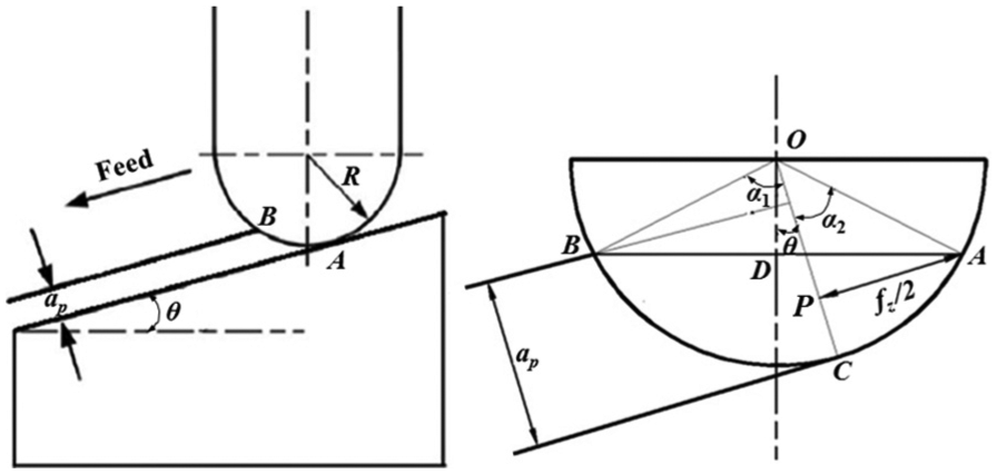
In the milling process of plane, the effective milling radius remains constant at different contact positions, which makes an accordant cutting amount and a steady cutting force wave in a cycle of milling. As shown in Figure 1, the effective milling radius in milling process of a plane can be obtained by
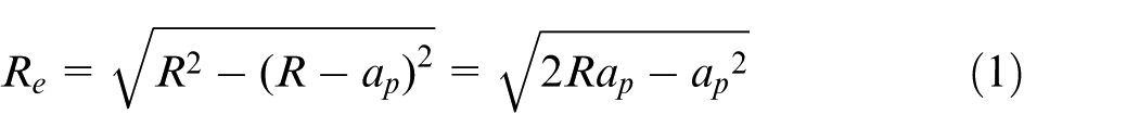
In which, R is the radius of cutting tool, and ap is the cutting depth.
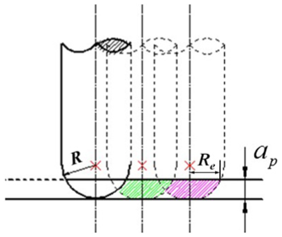
Cutting amount variation in plane milling.
As shown in Figure 2, for the variation of geometric features of the curved surface, the instantaneous cutting amount changes at different contact positions between cutting tool and workpiece, which makes the effective milling radius changes continuously, and the cutting force fluctuates sharply.
Cutting amount variation in curved surface milling.
The calculation of effective milling radius
The calculation of effective milling radius
for upslope
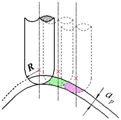
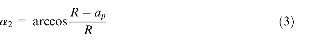
When the slop at a certain point on the tool path curve is positive in the machining of curved surface, it is just defined as upslope. As shown in Figure 3, the actual cutting edge is segment AB, and the effective milling radius is segment AD, which is also the maximum milling radius.

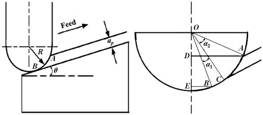
Micro-unit milling for upslope plane machining.
As shown in Figure 3,
Then, substitute

The calculation of effective milling radius
for downslope
When the slop at a certain point on the tool path curve is negative in the machining of curved surface, it is just defined as downslope. As shown in Figure 4, the effective milling radius is one of the segments BD and AD, and it is determined by incline angle
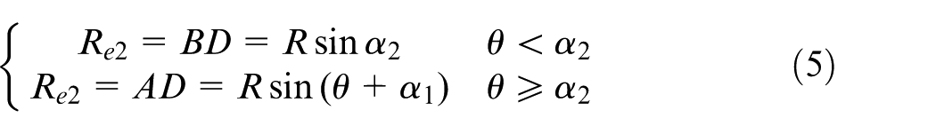
Micro-unit milling for downslope plane machining.
As shown in Figure 4, segment AP equals to
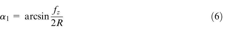
Substitute equations (3) and (6) into equation (5), then the effective milling radius
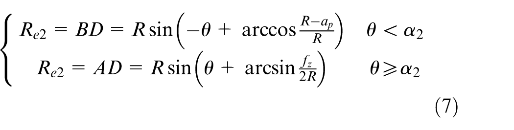
From equations (4) and (7), it can be found that for the continuous change of the incline angle for curved surface, the instantaneous cutting amount is changing all the time.
Experimental system and method
The research on the tool wear in high-speed milling of Inconel 718 curved surface based on the cutting tool geometrical parameters and the cutting force is conducted by setting up a series of experiments. The material and equipment needed in experiments and the experimental method are shown in this section.
Experimental equipment and workpiece material
Machine tool
High-speed three-axis vertical milling machine tool Mikron HSM 500 with HEIDENHAIN iTNC 530 NC system is adopted to conduct the processing. Its repeatability positioning accuracy is 5 µm, the machining precision is 0.1 µm and the highest spindle speed can reach to 54,000 r/min.
Force-measuring device
The cutting force measuring system is composed of Kistler Multi-component Force Plate Type 9253B23, Multichannel Charge Amplifier Type 5080 and DAQ for DynoWare Type 5697 that are all made in Switzerland.
Observation device of tool wear
A VHX-600E ultra-depth of field three-dimensional (3D) digital microscope system produced by KEYENCE Corporation is used for observing the tool wear. In this system, a 1/1.8-inch-Charge-Coupled Device (CCD) is adopted, the maximum pixel number is 54 million and the amplification factor is between 20 and 5000.
Workpiece material
As shown in Figure 5, both Inconel 718 plane and Inconel 718 curved surface are set as test pieces. Face-milling part is a rectangular block with a dimension of 50 mm × 50 mm × 30 mm. The generatrix of the curved surface is a sine curve and the equation of it is

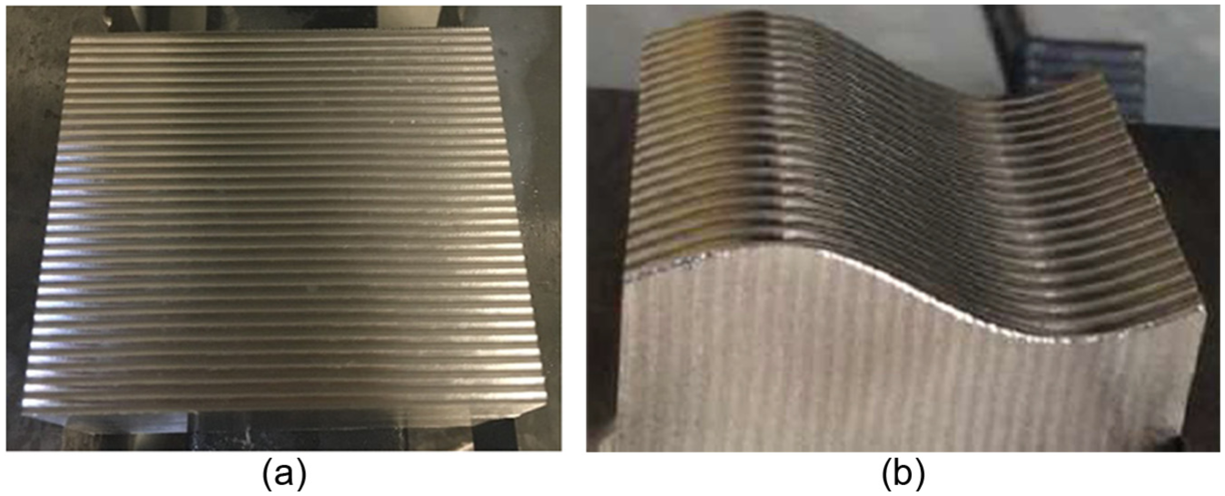
Test pieces: (a) plane piece and (b) curved surface piece.
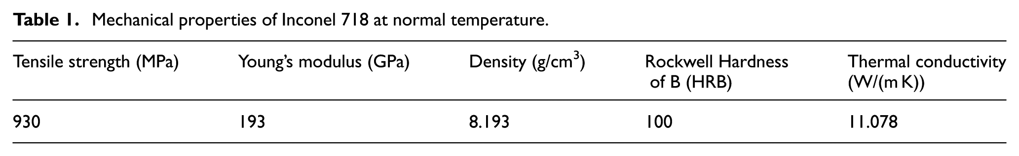
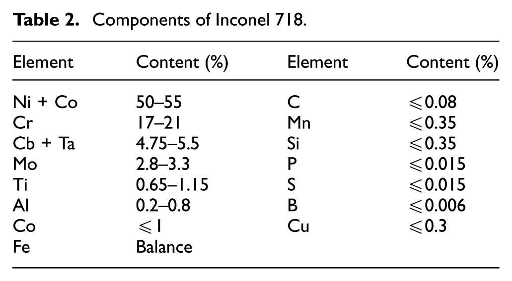
The mechanical properties and the nominal composition of the test piece material Inconel 718 are listed in Tables 1 and 2, respectively. By utilizing these test pieces, the tool wear experiments based on high-speed milling are conducted.
Mechanical properties of Inconel 718 at normal temperature.
Components of Inconel 718.
Milling tool
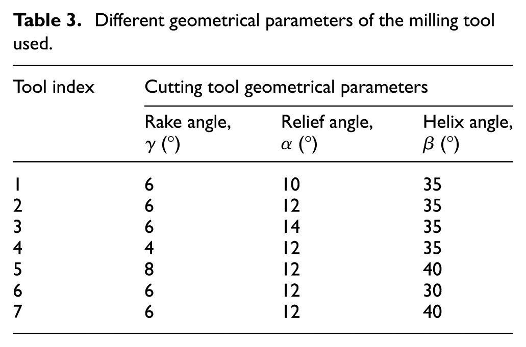
In this study, the ball-end milling tool with four flutes made by NTM Corporation is selected for studying the tool wear in high-speed milling based on the cutting tool geometrical parameters and the cutting force. The coated material of the milling tool is AlTiN, and the geometrical parameters are listed in Table 3. From Table 3, the rake angle is 4°, 6° and 8°, the relief angle is 10°, 12° and 14° and the helix angle is 30°, 35° and 40°, respectively. Totally, seven kinds of milling tools listed in Table 3 are used to study the tool wear based on cutting tool geometrical parameters and cutting force in the same milling condition for Inconel 718 curved surface.
Different geometrical parameters of the milling tool used.
Experimental procedure
Experimental study is the main method for conducting the investigation. Some correlated concepts, rules, parameters and details that are necessary for the experiments need to be put forward at first.
Calculation for effective milling speed
This study aims to investigate the tool wear in high-speed milling condition for the Inconel 718 curved surface based on cutting tool geometrical parameters and cutting force. The initial premise is to get the effective milling radius Re so as to satisfy the high-speed milling requirement. According to the effective milling radius, effective milling speed ve can be obtained by the effective milling radius and the spindle speed for experiments. For milling of the Inconel 718 curved surface in this study, the machining path is along with the generatrix of the curved surface. Because of the geometrical feature of the curved surface, the contact area between cutting tool and workpiece is changing all the time, which makes the effective milling radius of cutting tool changes constantly. According to the experimental results and the processing experience, the cutting depth ap is selected as 0.1 mm and the feed per tooth fz is 0.01 mm/z, and the spindle speed n is 10,500 r/min. Cutting tool radius R is equal to 3 mm. Based on equations (4) and (7), the effective milling radius Re for different positions of the sine curve in milling process is shown in Figure 6.
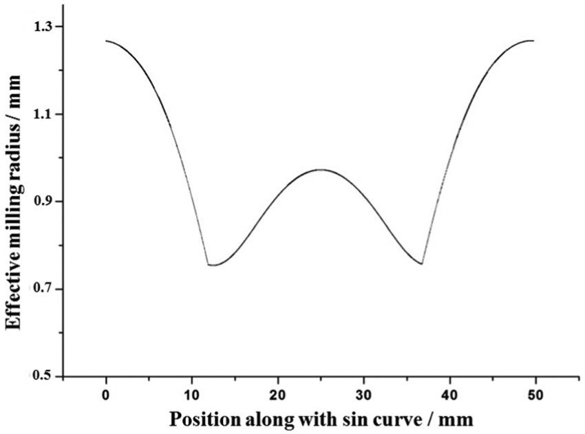
Effective milling radius for different positions of the sine curve.
The result shows that the smallest effective milling radius is 0.768 mm from Figure 6. In this way, the effective milling speed ve with the unit of m/min is expressed as

Then, substitute the smallest effective milling radius into equation (9), as a result,
Measure principle of tool wear zone
In order to study the influence of cutting tool geometrical parameters on the tool wear in high-speed milling of Inconel 718 curved surface, the measure principle of tool wear zone and the experimental detail for measuring strategy are given for the better understanding of this study.
In the milling process, the tool wear degree is evaluated by the maximum width of flank wear (VBmax) after a predetermined time interval or cutting length. As shown in Figure 7, cutting edges A, B, C and D are monitored for their different cutting features. For the cutting feature of cutting edges A and B is the same and the cutting feature of cutting edges C and D is the same, the average tool wear values of cutting edges A and B as C and D are taken as the final tool wear values, respectively. The measure points are at the same distance from the position of tool nose point. The distance between the measure point and the tool nose point is the smallest effective milling radius. In this way, the measure point continuously participates in cutting by calculating. Then, VHX-600E ultra-depth of field 3D digital microscope system is used for observing the tool wear.
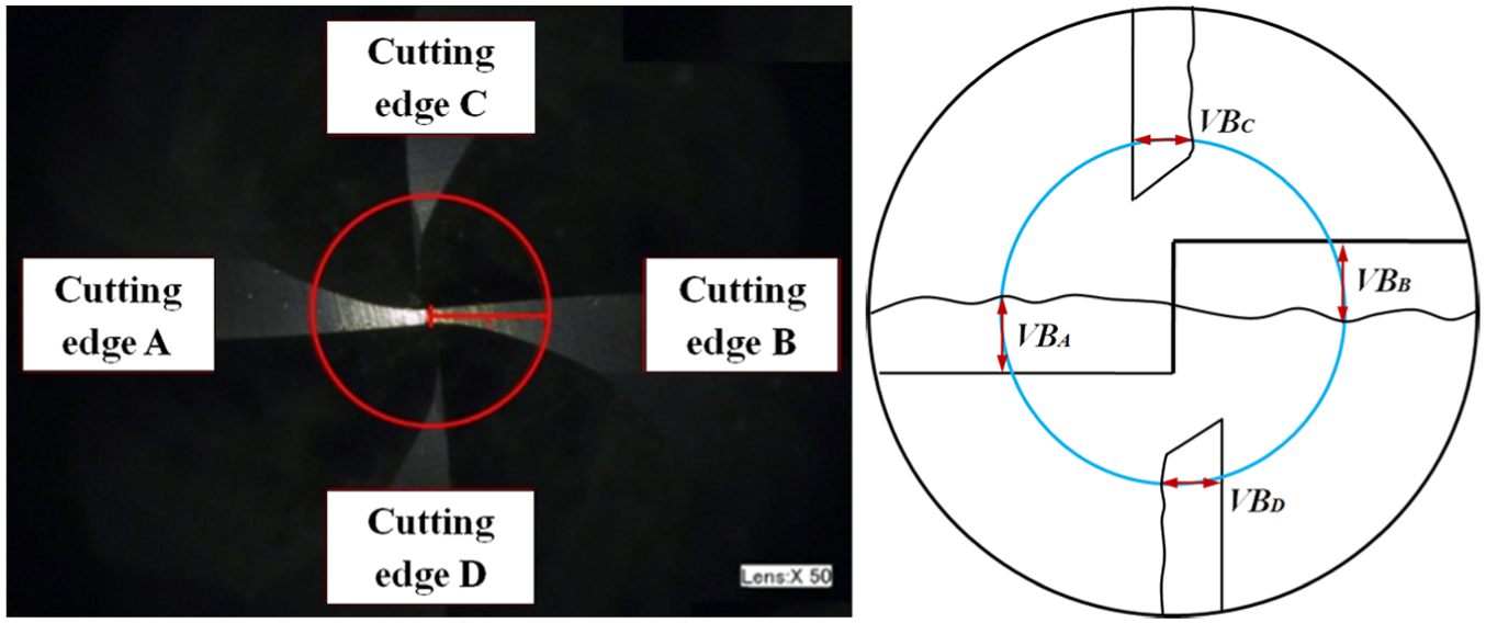
Measure principle of tool wear zone.
In order to better express the tool life, equal cutting length principle is used to investigate the tool wear in high-speed milling of Inconel 718 curved surface. Based on this principle, three steps are divided for measuring the tool wear degree, as shown in Figure 8. At step I, just initial wear stage, two sine lines cutting is defined as one cutting segment, and step I contains one cutting segment. At step II, just fast wear stage, five sine lines cutting is defined as one cutting segment, and step II contains one cutting segment. Then, the tool wear goes to step III, which is a relatively stable wear stage. For step III, 10 sine lines cutting is defined as one cutting segment. The maximum width of the flank wear is measured after finishing each cutting segment, and the cutting force value is measured at the middle of the last sine line cutting of each cutting segment. The experiment is finished when the cutting edge of cutting tool has lager area chipping, just the tool failure.
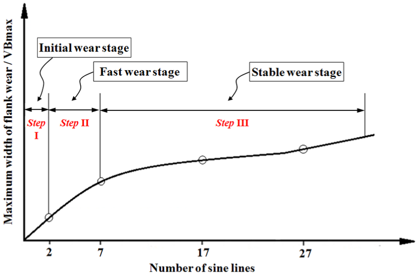
Three stages of tool wear.
Results and discussion
As mentioned above, the experiments are conducted under various combinations of rake angle, relief angle and helix angle of the cutting tool. Then, the analysis for the influence of cutting tool geometrical parameters on tool wear and cutting force are given according to the experimental results in this section.
Influence of the geometrical feature of parts on tool wear and cutting force
Experiments are carried out to investigate the influence of the geometrical feature of parts on tool wear and cutting force based on plane milling and curved surface milling. On the basis of the experimental results using tool 2 in Table 3, the flank-face wear for high-speed milling of Inconel 718 plane and Inconel 718 curved surface is shown in Figure 9 based on the measuring principle of tool wear zone in section “Experimental system and method.” It can be obviously found that the tool wear rate of curved surface milling is much quicker than that of plane milling, and the flank-face wear process of the coated cutting tool in curved surface milling can be described in three steps before tool failure: just initial wear stage, fast wear stage and stable wear stage. However, the tool wear of initial wear stage and fast wear stage for plane milling is not obvious, and the tool wear process of stable wear stage lasts for a quite long time. As shown in Figure 10, the experimental results show that the dominant tool wear is flank-face wear with less coating damage after 11 cutting segments for plane milling, and the tool wear for the curved surface milling contains rake-face wear, flank-face wear and chipping simultaneously. For the cases of curved surface milling after the first cutting segment, the width of flank-face wear zone is 34.0 µm. After machining of 11 cutting segments, the width of flank-face wear zone of tool 2 reaches to 14.6 µm for plane milling, however, the tool 2 is failure for the curved surface milling.
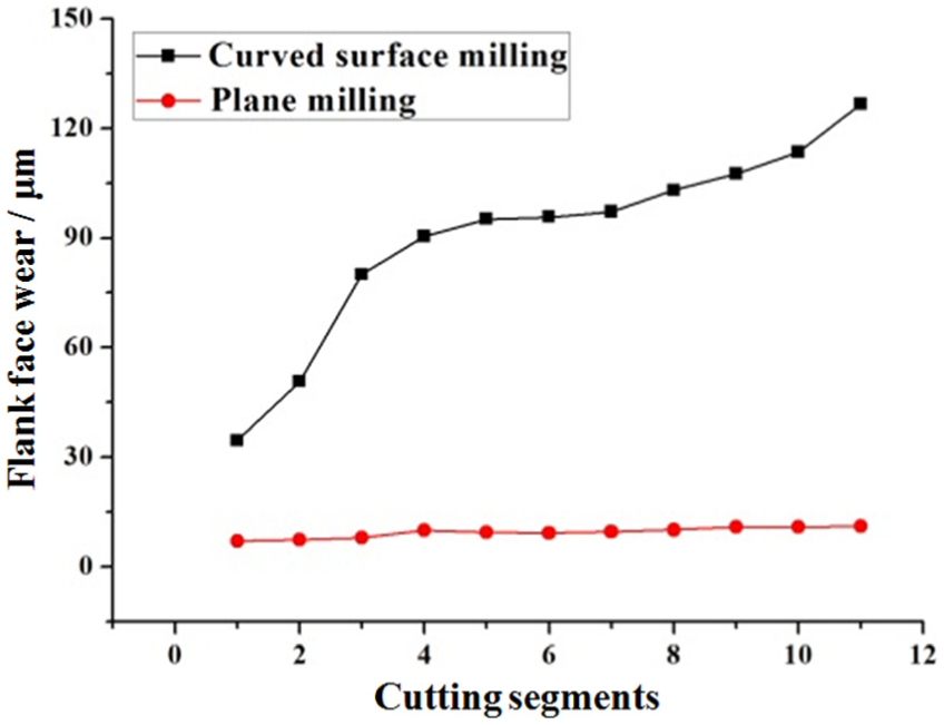
Variation of flank-face wear for tool 2 for plane milling and curved surface milling.
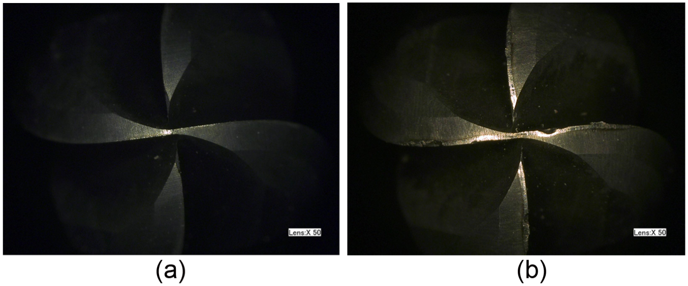
Tool wear comparison between plane milling and curved surface milling: (a) tool wear of plane milling and (b) tool wear of curved surface milling.
For that the cutting force can truly manifest the tool wear degree, it is undoubted that the smaller the cutting force and cutting force fluctuation, the slower the tool wear. The cutting force variations in plane milling and curved surface milling are truly different. To make comparable, the cutting force is measured at the middle of the last sine line cutting of each cutting segment. As shown in Figure 11, the cutting force wave in plane milling test is more stable than that in curved surface milling test. Because of the geometrical feature change of curved surface, the cutting force fluctuates sharply, and the amplitude of cutting force is larger than that in plane milling test. The cutting force variation for plane milling and curved surface milling is shown in Figure 12. It can be concluded that the geometrical feature change of curved surface causes the larger cutting force and the large cutting force fluctuation and then leads to the faster tool wear.
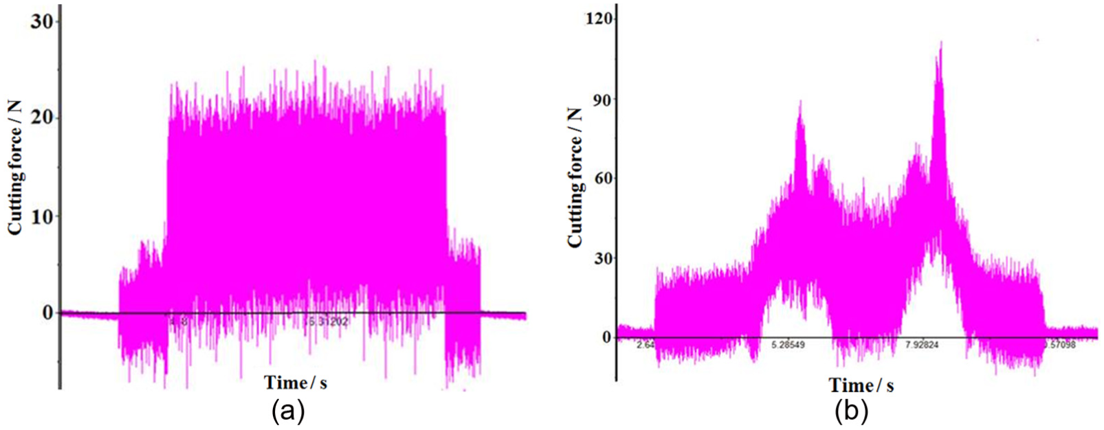
Cutting force signals for plane milling and curved surface milling: (a) cutting force of plane milling and (b) cutting force of curved surface milling.
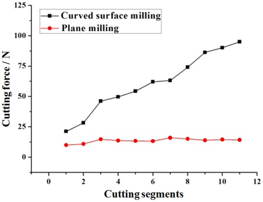
Cutting force variation in plane milling and curved surface milling.
Influence of the rake angle on tool wear and cutting force
Two groups of cutting tools can be used to study the influence of the rake angle on tool wear and cutting force from Table 3, just tool 2 and tool 4 and tool 5 and tool 7. The rake angles for tool 2 and tool 4 are 6° and 4°, respectively, and that for tool 5 and tool 7 are 8° and 6°, respectively. However, the helix angle for tool 2 and tool 4 is 35° and that for tool 5 and tool 7 is 40°.
The average tool wear values of cutting edges A and B and C and D as the final tool wear values are measured in the high-speed milling process for Inconel 718 curved surface. The flank-face wear for tool 2 and tool 4 is shown in Figure 13, and it can be clearly seen that tool 4 has the better performance than tool 2 for the smaller rake angle. After three cutting segments, cutting edge B of tool 2 emerged chipping. After five cutting segments, cutting edge A also emerges chipping, and the flank-face wear reaches to 75.50 and 118.92 µm for cutting edges A and B, respectively. Although increasing the rake angle can sharp the cutting edge and reduce the extrusion for the surface to be processed, the low ductility of Inconel 718 leads to the contact length between the chip and the rake face to be short. The strength and impact resistant ability can be reduced by increasing the rake angle, which is extremely detrimental to the processing of brittle materials. When using a small rake angle, the chip–tool contact length is increased leading to reduction in cutting force and machining temperature, which is a benefit for enhancing the tool life. Figure 14 shows the flank-face wear for tool 5 and tool 7, and an opposite phenomenon is happened that tool 5 with a bigger rake angle has the better performance than tool 7. Comparing tool 7 with tool 2, the only difference is the helix angle. In this way, it is the indirect evidence that the helix angle of cutting tool has bigger influence on the tool wear and can cover the effect of the rake angle on tool wear.
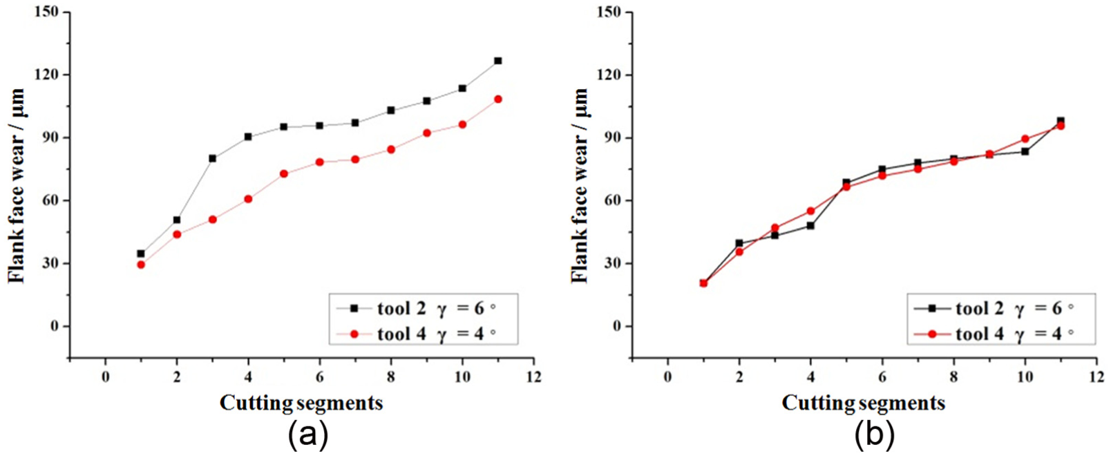
Variation of flank-face wear for tool 2 and tool 4 with different rake angles: (a) average tool wear of cutting edges A and B and (b) average tool wear of cutting edges C and D.
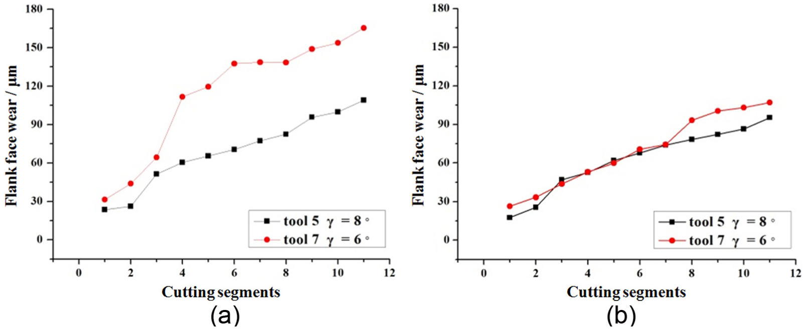
Variation of flank-face wear for tool 5 and tool 7 with different rake angles: (a) average tool wear of cutting edges A and B and (b) average tool wear of cutting edges C and D.
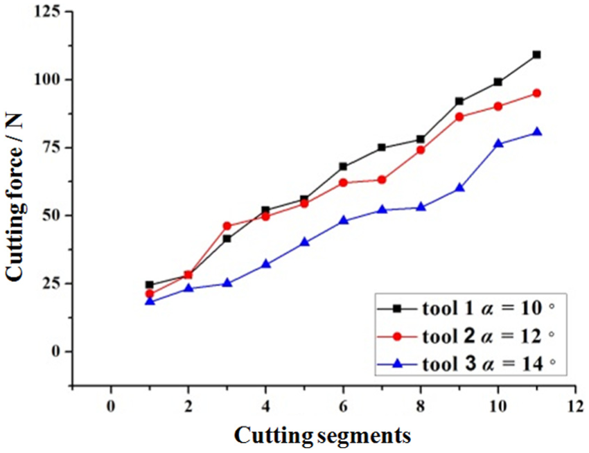
Figure 15 shows the evolution of the resultant cutting force with different rake angles. The cutting force variation increases all the time with the increase in tool wear, and the cutting force using tool 2 is higher than that using tool 4 during the entire process. It is conducted that small rake angle has greater strength and has superiority in high-speed milling of Inconel 718 curved surface.
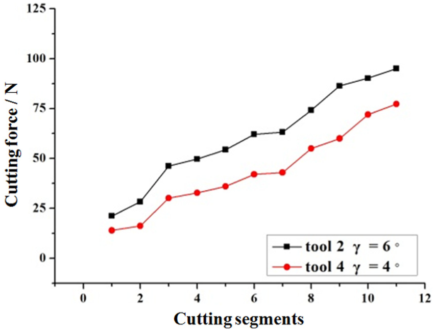
Cutting force variation for tool 2 and tool 4 with different rake angles.
Influence of the relief angle on tool wear and cutting force
From Table 3, tool 1, tool 2 and tool 3, which have the same rake angle and helix angle, are used to study the influence of the relief angle on tool wear and cutting force. After monitoring the performance of these three cutting tools with different relief angles, it can be obviously found that tool 3 (α = 14°) has the best performance and tool 2 (α = 12°) is better than tool 1 (α = 10°), as shown in Figure 16 in the stable wear stage. Chipping at the flank face for tool 1 and tool 2 is emerged after three cutting segments, and the chipping width finally reaches to 142.38 and 120.45 µm for cutting edge B, respectively, which is the main cause of the tool failure. While the flank wear zone of tool 3 finally reaches to 105.24 µm for cutting edge B, tool 3 still has the ability of stable cutting as shown in Figure 17. For the relief angle has a close relationship with the contact area between flank face and machining surface, the contact area between cutting tool and workpiece can be reduced and the friction can be lessened by increasing the relief angle. In another way, increasing the relief angle can also sharp the cutting edge and reduce the extrusion for the surface to be processed. Therefore, increasing the relief angle can enhance the tool life in high-speed milling of Inconel 718 curved surface.
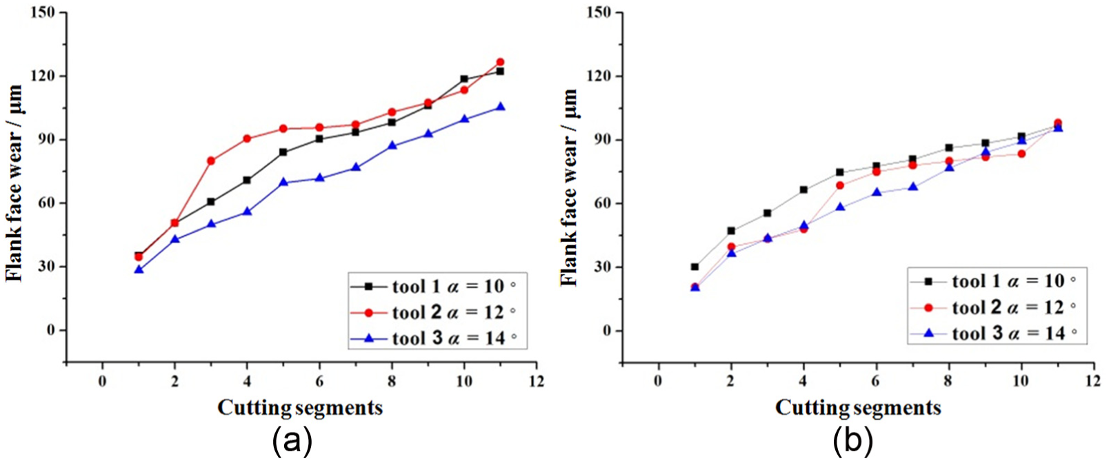
Variation of flank-face wear for tool 1, tool 2 and tool 3 with different relief angles: (a) average tool wear of cutting edges A and B and (b) average tool wear of cutting edges C and D.
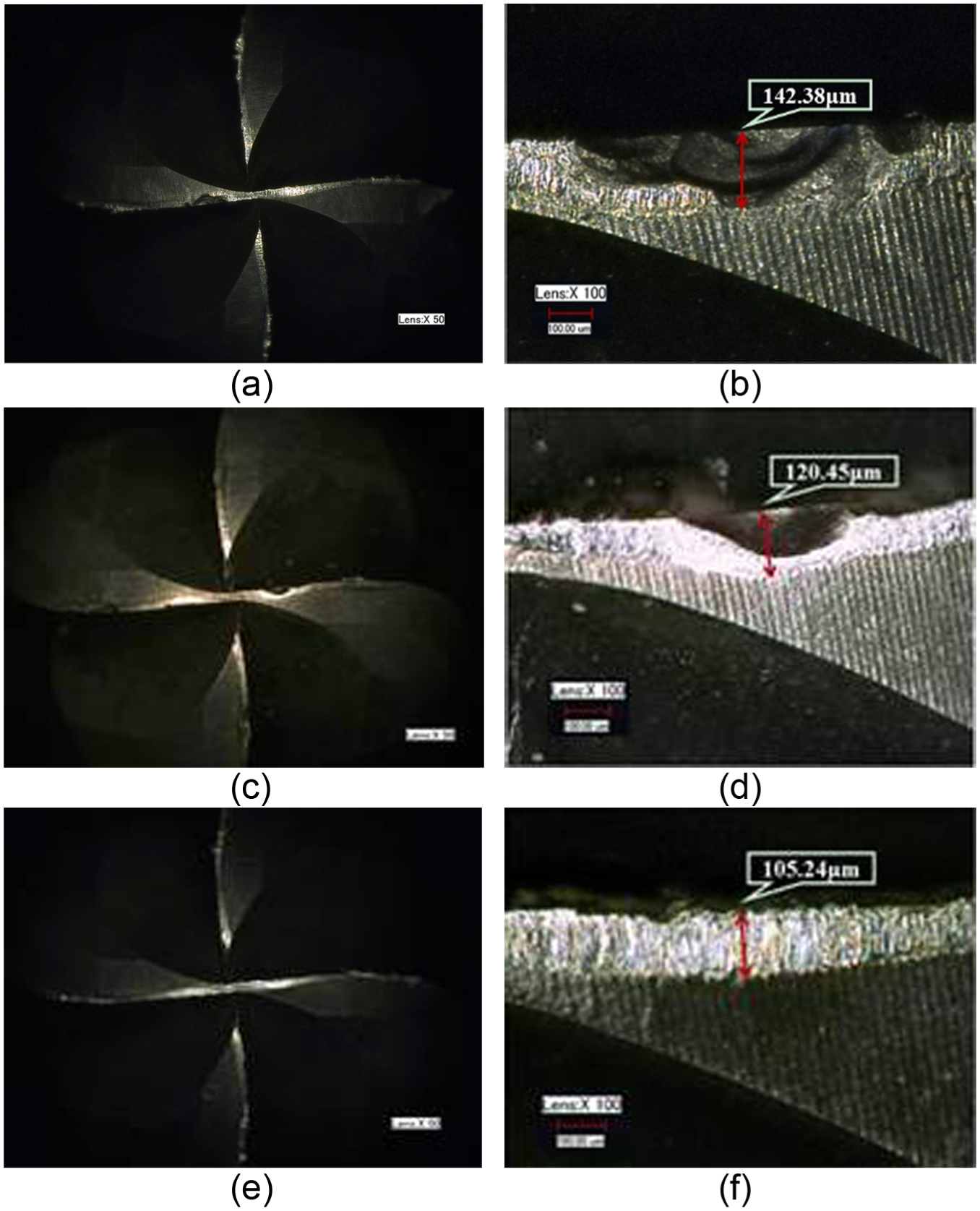
Tool wear comparison between different relief angles: (a) flank-face wear of tool 1 for cutting edge B, (b) flank-face wear of tool 2 for cutting edge B and (c) flank-face wear of tool 3 for cutting edge B.
Figure 18 shows the evolution of the resultant cutting force with different relief angles. It can be seen that the resultant cutting force has a same tendency along with the tool wear, and the cutting force based on tool 3 is the lowest than others. The cutting force of tool 1 and tool 2 is rapidly increasing at the beginning of the process then stepped into a stable increase stage. In general, the tool wear has a large effect on the cutting force, and decreasing relief angle leads to chipping and cutting force increasing.
Cutting force variation for tool 1, tool 2 and tool 3 with different relief angles.
Influence of the helix angle on tool wear and cutting force
Tool 2, tool 6 and tool 7 in Table 3, which have the same rake angle and relief angle, are used to study the influence of the helix angle on tool wear and cutting force. After monitoring the performance of these three cutting tools with different helix angles, Figure 19 shows the comparison of flank-face wear for three cutting tools with different helix angles. The results show that tool 6 (β = 30°) has the longest tool life than the other two cutting tools, and on average, tool 2 (β = 35°) has a better performance than tool 7 (β = 40°). After three cutting segments, the chipping of tool 2, tool 6 and tool 7 are 108.92, 91.3 and 80.3 µm for cutting edge B, respectively, as shown in Figure 20. As we all known that enhancing the helix angle of the cutting tool can make cutting edge length longer and decrease the cutting force on the unit of cutting edge, increasing helix angle is benefit for enhancing the tool life. However, the oversize helix angle may not only lead to large vertical forces on cutting tool but also bring out poor discharge of the chip and then the rising cutting temperature will shorten the tool life. It can be seen that in high-speed milling of Inconel 718 curved surface, helix angle β = 30° has the best performance, and the increasing helix angle leads to the tool wear rapidly in this study.
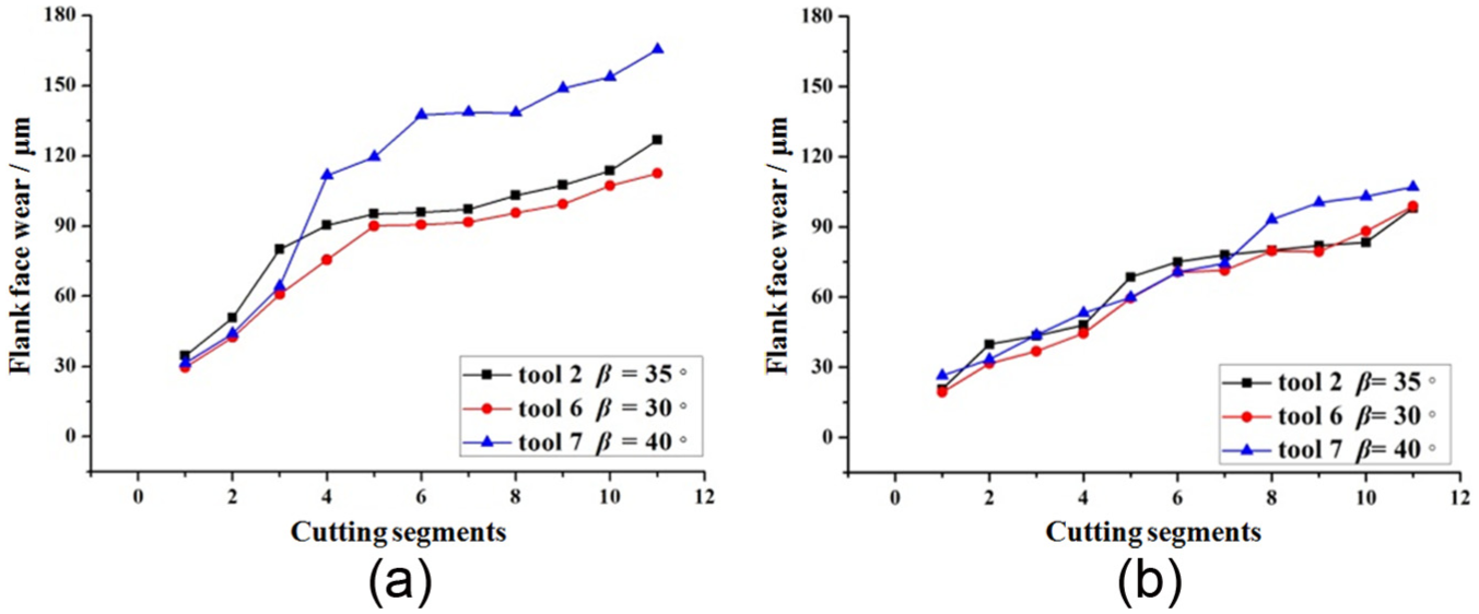
Variation of flank-face wear for tool 2, tool 6 and tool 7 with different helix angles: (a) average tool wear of cutting edges A and B and (b) average tool wear of cutting edges C and D.
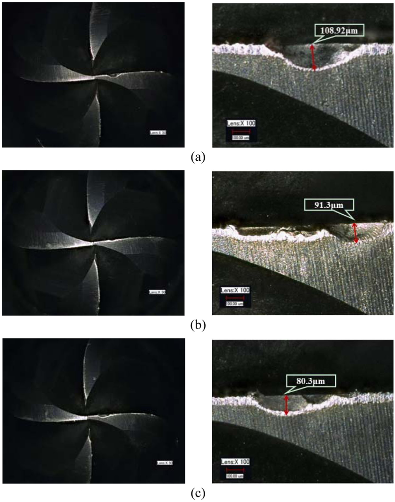
Tool wear comparison between different helix angles: (a) flank-face wear of tool 2 for cutting edge B, (b) flank-face wear of tool 6 for cutting edge B and (c) flank-face wear of tool 7 for cutting edge B.
In the same way, Figure 21 shows the evolution of the resultant cutting force with different helix angles. It can be seen that the resultant cutting force has a same tendency along with tool wear. The cutting force based on tool 7 is the largest than others. The difference of cutting force for tool 7 and tool 2 is greater than that for tool 2 and tool 6, and it is probably caused by chipping which emerges at both of the cutting edges A and B. In general, decreasing helix angle results in longer tool life and decrease in cutting force, due to the reduced vertical load on cutting tool.
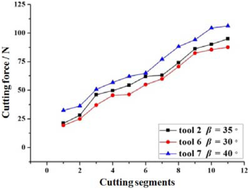
Cutting force variation for tool 2, tool 6 and tool 7 with different helix angles.
Conclusion
For Inconel 718 parts with curved surface, the geometrical features are changing continuously. In this way, the instantaneous cutting amount is changing, in turn leading to the sharp fluctuation of cutting force, which will aggravate the tool wear and affect the high-speed milling quality significantly. In this study, the tool wear in high-speed milling of Inconel 718 curved surface based on cutting tool geometrical parameters is investigated with coated cutting tool, and the cutting force in milling process is also analyzed. The following conclusions can be made:
The tool wear has a large effect on the cutting force, and the cutting force variation has a same tendency with the tool wear. Therefore, the cutting force variation can manifest the tool wear degree.
The failure type of coated cutting tool in plane milling and curved surface milling after the same cutting length is different. The dominant tool wear and damage in plane milling are flank-face wear and less coating damage, while in curved surface milling, the dominant tool wear and damage are rake-face wear, flank-face wear and chipping. The geometrical feature change of curved surface, which caused the sharp fluctuation of cutting force, leads to the faster tool wear.
The experimental results show that the cutting tool geometrical parameters seriously affect the tool wear and the tool life. It can be conducted that in high-speed milling of Inconel 718 curved surface, the small rake angle has greater strength and has superiority, the relief angle increasing can enhance the tool life, and the tool life is decreased with the increasing of helix angle for the cutting tool whose helix angle is larger than 30°.
The research achievements in this study provide a theoretical basis for cutting tool wear mechanism and cutting tool geometrical parameter selection in high-speed milling of Inconel 718 curved surface, which are of vital importance for realizing the high quality and high efficient machining for the Inconel 718 parts with curved surface.
Footnotes
Acknowledgements
The authors thank the anonymous reviewers for their comments which led to improvements of this article.
Declaration of conflicting interests
The author(s) declared no potential conflicts of interest with respect to the research, authorship, and/or publication of this article.
Funding
The author(s) disclosed receipt of the following financial support for the research, authorship, and/or publication of this article: The project was supported by the National Natural Science Foundation of China (nos 51575087 and 51675081), National Science and Technology Major Project of China (no. 2016ZX04001-002), Innovation Project for Supporting High-level Talent in Dalian (no. 2016RQ012) and the Fundamental Research Funds for the Central Universities (no. DUT17LAB13).