
Abstract
Aerospace material Inconel 718 is well known for its poor machinability. This article presents an experimental study of the cutting forces in high-speed dry milling of Inconel 718 using a milling cutter with coated carbide inserts. An assessment of the cutting force variations is conducted using statistical approaches and wavelet decomposition taking into consideration the dynamic effects. The averaged peak force values, the peak force variation range and distribution, and the skewness are evaluated. It shows that cutting speed does not have a significant influence on the averaged peak cutting force for the range tested. The tool–workpiece vibrations at the cutter entry stage and exit stage are generally more significant. Moreover, wavelet packet decomposition at level 3 with the DB4 wavelet and Shannon entropy is found to be an effective approach to identify the chatter onset.
Introduction
Nickel-based superalloys are important materials for modern aircraft and aerospace. 1 The increasing demands for machining advanced aerospace materials such as superalloys to make complex modern aerospace components have posed challenges to the manufacturing industry due to the poor machinability of the materials. Inconel 718, a precipitation-hardenable Nickel–Chromium superalloy, is one of the most important superalloys in aerospace. 2 It combines desirable properties like high strength with outstanding durability and corrosion resistance and has been commonly used in high-end applications like jet engine components, gas turbines, pumps, rockets, spacecraft, nuclear reactors, or tooling where these properties are required. However, Inconel 718 is very difficult to machine due to its excellent physical properties such as very high yield stress and high hardness at elevated temperatures, low thermal conductivity, and high tendency to adhesion and work-hardening. These characteristics affect significantly the part quality, tool life, and productivity. Cutter material often loses its strength more quickly than the work material itself as the latter is very temperature resistant. High tool wear rates occur due to very high time varying mechanical and thermal loads exerted on the cutting edges of the cutter, which deteriorates the accuracy and surface finish of the machined parts.1–3
In view of the challenges, there is a need to optimize the machining process parameters such as cutting speed, feed, and depth of cut (DOC). Cutting forces are frequently used to assess the adequacy of the cutting parameters. In the cutting of superalloys, a built-up edge is usually formed when cutting at low cutting speeds and disappears as the speed is raised. Very high temperatures are generated even at relatively low speeds in the flow zone at the tool/work interface, which results in destruction of the cutting edge under the action of shear and compressive stresses acting at high-temperature aerospace. 1
Alauddin et al. 4 experimentally investigated the influence of machining conditions on the average cutting forces in the end milling of Inconel 718 under dry conditions using uncoated carbide inserts. It was observed that the cutting forces decrease as the cutting speed increases (11–25 m/min) for up- and down-mode end milling. Nevertheless, the cutting speed range in the study by Alauddin et al. 4 was relatively low. In the study by Choudhury and El-Baradie, 5 it was reported that the tool life of coated tools was not better than that of the uncoated tools through a series of machining experiments of cutting Inconel 718 using coated and uncoated carbides. However, this is controversial to the results in the study by Devillez et al., 6 which concluded that in dry cutting Inconel 718 superalloy, a coating is absolutely necessary to obtain a sufficient tool life and an acceptable surface integrity for the machined parts. Lorentzon et al. 7 observed from turning experiments under dry cutting conditions that when machining alloy 718 at lower cutting speeds (below 50 m/min), the chip produced is long and continuous. At higher cutting speeds (above 100 m/min), the chip produced is segmented. This transition was believed to be caused by both thermal softening and material damage. Ezugwu et al. 8 studied the performance of multiplayer-coated carbide tools in the turning of a martensitic stainless steel without coolant and found that the predominant tool failure modes at higher speed conditions were significant nose wear and chipping/fracture of the cutting edge. Liao et al. 9 concluded that cutting temperature, which is believed to be related to the cutting speed, plays a very important role in cutting of Inconel 718. However, it is noted that the effect of feed on cutting force is relatively insignificant.
Recently, Devillez et al. 10 presented the results of surface integrity and cutting forces in turning Inconel 718 alloy under wet and dry conditions. With the increase of the cutting speed from 40 m/min in dry condition, the cutting forces initially decrease and present a minimum value at the cutting speed of 60 m/min, which is possibly associated with thermal softening. When cutting speed increases further from 60 to 80 m/min, an increase of cutting force was observed, which was believed to be due to the effect of strain rate sensitivity that becomes more predominant than thermal softening. 10 However, in that experimental study, only three sets of cutting speeds were considered. Gao et al. 11 showed that during the process of high-speed machining of nickel-based superalloy, the material presents serrated chips, and that cutting speed and feed rate are sensitive factors affecting shear stress, shear strain, and shear strain rate.
It is worth noting that during the machining process, especially in milling operations, even under a steady cutting condition, the cutting forces are not static. This can be attributed to the inhomogeneity of the workpiece material, the dynamic interaction between workpiece and cutting tool, and the varying chip load. Li et al. 3 reported the cutting force variation phenomenon during the milling of Inconel 718. Chen and Li 12 proposed an approach to predict the state of tool wear in real time by measuring the cutting force variations in the milling of Inconel 718, which was based on a correlation between the cutting force components and the wearland width. Obviously, the cutting force variation phenomenon can be used to assess the cutting condition and to detect the development of tool wear and the occurrence of chatter. Unfortunately, more research study is yet needed to study the cutting force variations.
A recent trend of improving the machining processes of difficult-to-cut materials for the aerospace industry is to use dry cutting operations that are more environmentally friendly and reduce energy consumption and operation costs. 13 Actually, a series of experiments examining the effects of varying the cutting fluid supply pressure and direction of the jet when finish turning Inconel 718 was presented in the study by Sharman et al. 14 Surprisingly, it was found that no increase in tool life was observed when using the cutting fluid up to 450 bar pressure. Traditionally, for machining nickel-based alloys at very low cutting speed of 20–30 m/min, cemented carbide tools are used, and the K20 grade appears to be the best for cutting Inconel 718. New tool surface coatings with a potential for dry machining under higher cutting speeds have been developed, so that higher cutting speeds of up to 100 m/min under dry cutting conditions may be achieved with coated carbide tools. 13
This article presents an experimental study of the cutting forces in the high-speed end milling of Inconel 718 alloy with coated carbide inserts under the dry cutting condition. A comprehensive assessment of the cutting forces based on a statistical approach is conducted. In this assessment, the averaged peak forces, the range of the peak force variation, and the distribution characteristics of the peak values are used to evaluate the effects of cutting parameters. The dynamic effects in the cutting process are also taken into consideration through wavelet-based signal processing.
Experimental methodology
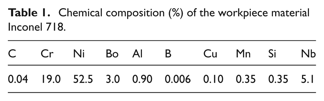
In this study, a Deckel Maho 5-axis computer numerical control (CNC) milling center was used to conduct the cutting experiments. This machine tool is with relatively good stiffness. The workpiece was prepared from a nickel-based alloy Inconel 718 square bar into a dimension of 60 × 60 × 100 mm3. The material was hardened and tempered with a tensile strength of 965 N/mm2, and the yield point was 550 N/mm2. The chemical composition in terms of percentage is shown in Table 1.
Chemical composition (%) of the workpiece material Inconel 718.
Appropriate selection of suitable cutting tools is important for cutting difficult-to-machine material. To facilitate the investigation of the cutting force variation and also to avoid the effects of tool runout, a single tooth milling cutter with an indexable insert tip from Mitsubishi Materials Corporation was chosen. The cutter composes a diameter 12 mm × 1 Tooth APX3000 shank-type milling cutter body and an AOMT123608 PEERMVP20RT BAP300 Milling Insert with 0.8 mm corner radius. It is a coated carbide insert with type M breaker, as shown in Figure 1(a). A wide range of materials can be cut by this cutting tool. The coating consists of (Al, Ti)N and has high strength to the substrate and good heat and oxidation resistance to enhance the tool life when machining hardened workpiece. The insert has the features of double-phased helical rake angles and tough cutting edge, which can achieve low cutting resistance. The special geometry can help to reduce the heat generation in cutting. The insert was screwed onto the shank-type cutter with a provided TPS25 clamp screw. The cutter was then installed into the shank holder from the 5-axis CNC machine, as shown in Figure 1(b). When the insert was set in the cutter body, the rake angle was 25°.
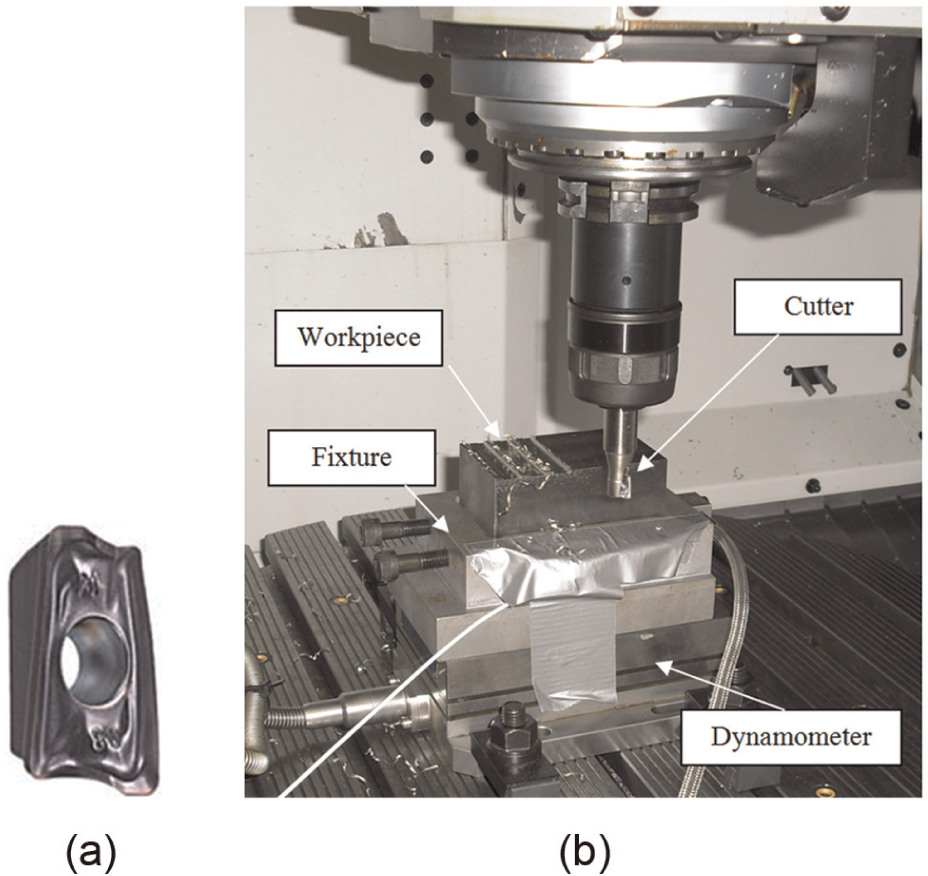
Experimental setup: (a) coated carbide insert, and (b) milling cutter, workpiece, and measurement sensor.
A Kistler Type 9257B dynamometer was used to measure the three orthogonal components of the cutting force, as shown in Figure 1(b). It has a good rigidity and high natural frequency. The workpiece block of Inconel 718 was mounted on the dynamometer through a fixture. The dynamometer was connected to a multichannel charge amplifier, and the output signal was acquired by a high-speed data acquisition (DAQ) card in a computer. The sampling rate was set as 2000 Hz. The cutting parameters for the experiment were chosen as follows:
Radial DOC (or width of cut): 12 mm (slot milling);
Axial DOC: 0.5, 1, and 2 mm;
Cutting speed: 140, 160, 180, 200, 220, 230, and 240 m/min;
Feed rate: 0.1, 0.14, and 0.18 mm/tooth.
A total number of 63 sets of cutting tests have been carried out using a full factorial experimental design. Dry cutting was employed without using any coolant or lubricant. Once all apparatus and DAQ were set up, a position configuration process was run to reset the default position of the coordinates on the CNC machine. This positioning process was done before each set of the tests and reposition the default Z-plane of the workpiece. Some pretests were carried out to ensure that all equipment worked properly. During the data postprocessing phase, an error was found for the data under the cutting condition of 0.5 mm DOC, 0.1 mm/tooth feed, and 240 m/min cutting speed. Therefore, that set of data has been discarded.
For a correct signal analysis, it is important to have a good understanding of different coordinate systems involved, which include the machine tool coordinate system, sensor coordinate system, and so on. A schematic view of the coordinate system of the dynamometer for cutting force measurement is shown in Figure 2. The dynamometer produces force readings in the x-, y-, and z-axis directions. In the cutting testing, the feeding of the tool was along the −Fx direction of the dynamometer.
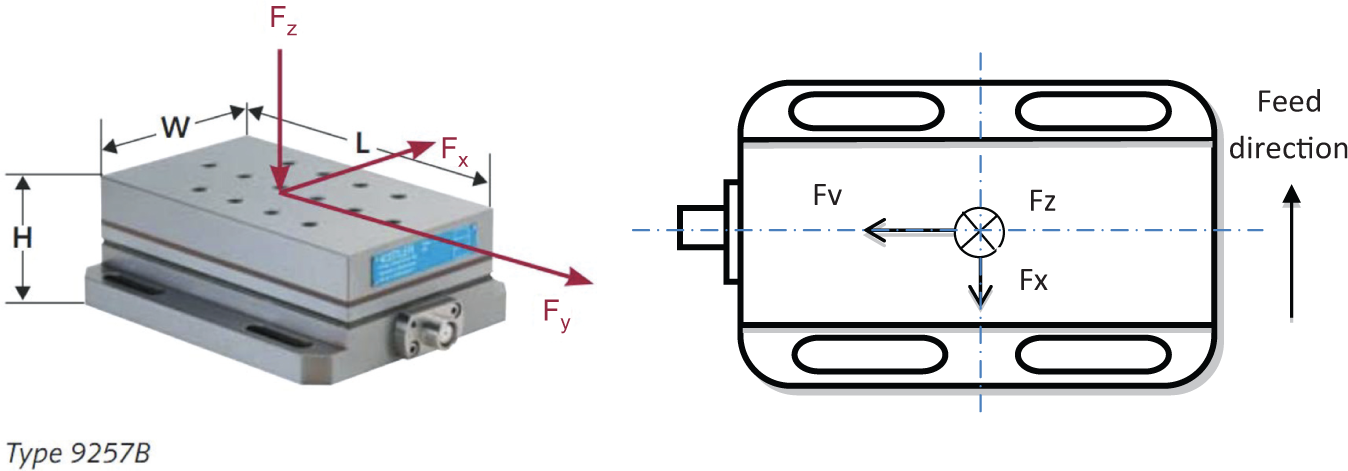
Coordinate system of the dynamometer.
Analysis approaches and results
Averaged peak force
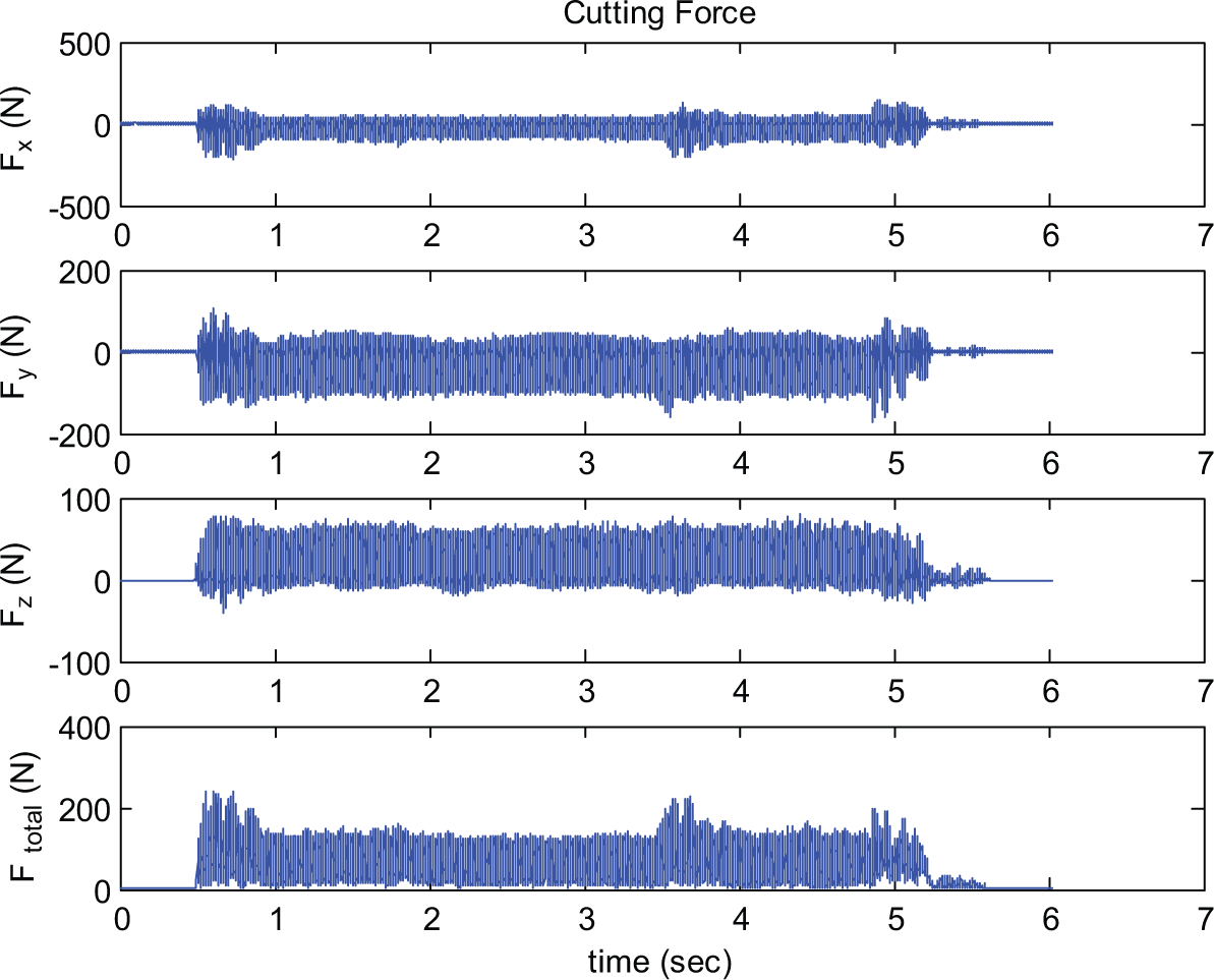
To understand the pattern of cutting force variation in milling of Inconel 718, typical waveforms of cutting force components measured in the experimental study are illustrated in Figure 3. The signals are corresponding to a cutting condition of 0.1 mm/tooth feed, 0.5 mm axial DOC, and 140 m/min cutting speed. Figure 3 shows the force components along the x, y, and z directions of the dynamometer, Fx, Fy, and Fz, respectively, and the total resultant force, Ftotal, which is the vector summation of the three force component as
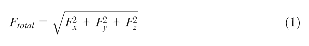
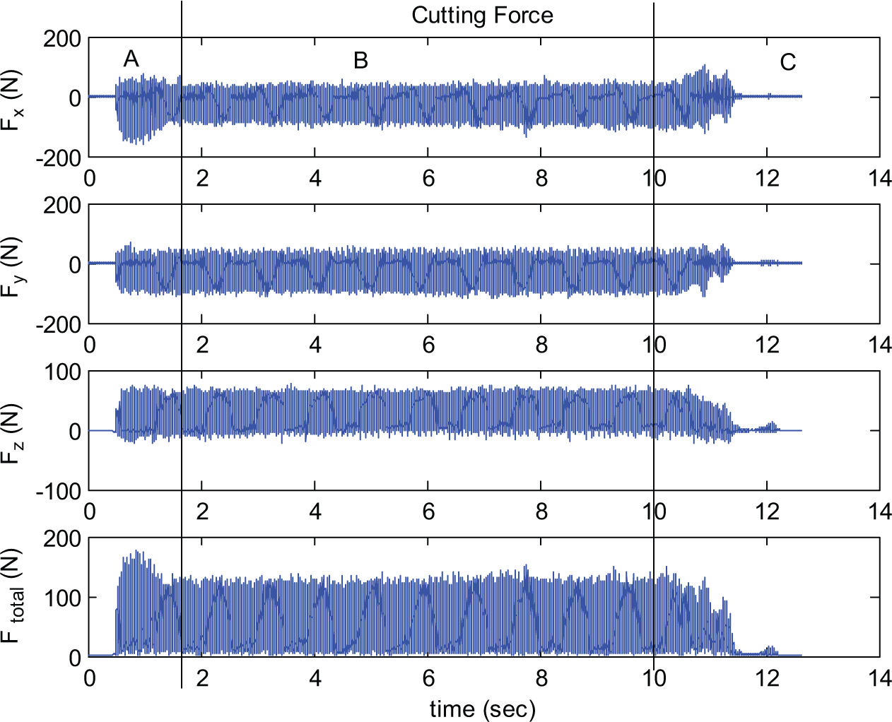
Typical cutting force waveforms.
A general profile of the force variation during the whole cutting pass can be observed from the waveforms, as shown in Figure 3. From cutter entered cutting to exit for a whole cutting length of 60 mm, the cutting force signals can be divided into three zones labeled as A, B, and C. This can be correlated to the cutter entering stage, steady-state cutting stage, and cutter exit stage, as shown in Figure 4. Both zone A and C show clear transient characteristics. When the cutter started engaging in cutting, there were significant variations of the force amplitudes. This might be caused by the transient cutting process in which the dynamic interaction between cutter and workpiece was significant. In between, there was a steady cutting stage where the peak forces show a stabilized pattern, until the cutter started to exit the cutting.
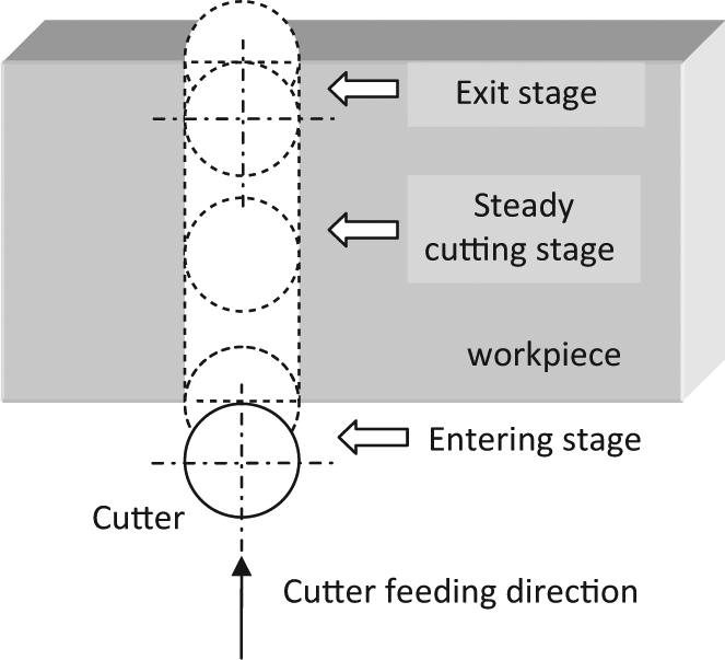
Three cutting stages in a cutting pass.
To examine the force pattern in more detail, a zoomed-in view of the force variation within three revolutions of the cutter at the steady stage was given in Figure 5, which includes the cutting force components along the x, y, and z directions and also the total resultant force using equation (1). For the milling cutter used in the cutting tests, there was only one insert. It means that for a slot milling process, the insert is only engaged in cutting for half of the cutter revolution, that is, for about 180°. The waveforms in Figure 5 clearly show the force variation along with the cutter revolution.
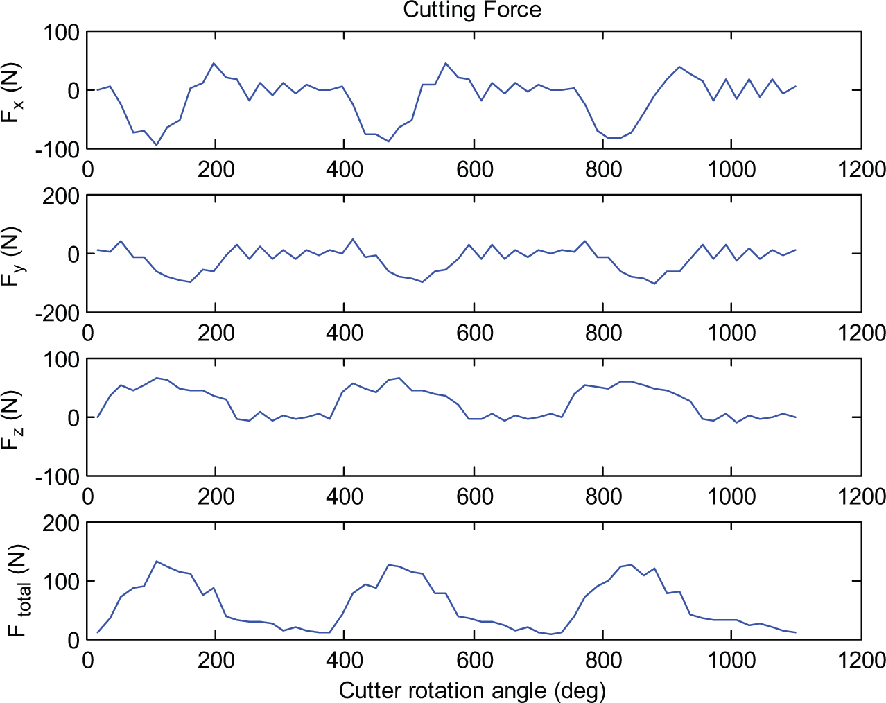
Cutting force waveforms within three revolutions of the cutter at the steady stage.
To investigate the effects of cutting parameters on the cutting forces, it is important to select representative cutting force values since the measured cutting forces are in a complex waveform. There are many different approaches for the assessment of cutting forces. In the time domain, the parameters that can be used to evaluate force level and variation include root mean square (RMS), peak-to-peak value (PTP), average value, peak value (amplitude), and so on. The peak cutting force value, which is in fact the absolute maximum value within one cutter revolution, is believed to be a very useful parameter since it represents the maximum cutting load the tool and workpiece endure during cutting. 15 For process optimization, small force amplitude is preferred under comparable chip load. But the variation of the peak force values can be affected by some disturbances such as tool–workpiece vibration and the inhomogeneity of the work material. In this study, averaged peak values of the total resultant cutting force are chosen to assess the influence of the cutting parameters. First, a considerable number of cutter revolutions in steady cutting stage is selected, which can be a few 100 revolutions. The peak force for each tool revolution is determined, and finally, the mean of all peak force values corresponding to a few 100 revolutions is calculated, which is referred to as averaged peak force in this study.
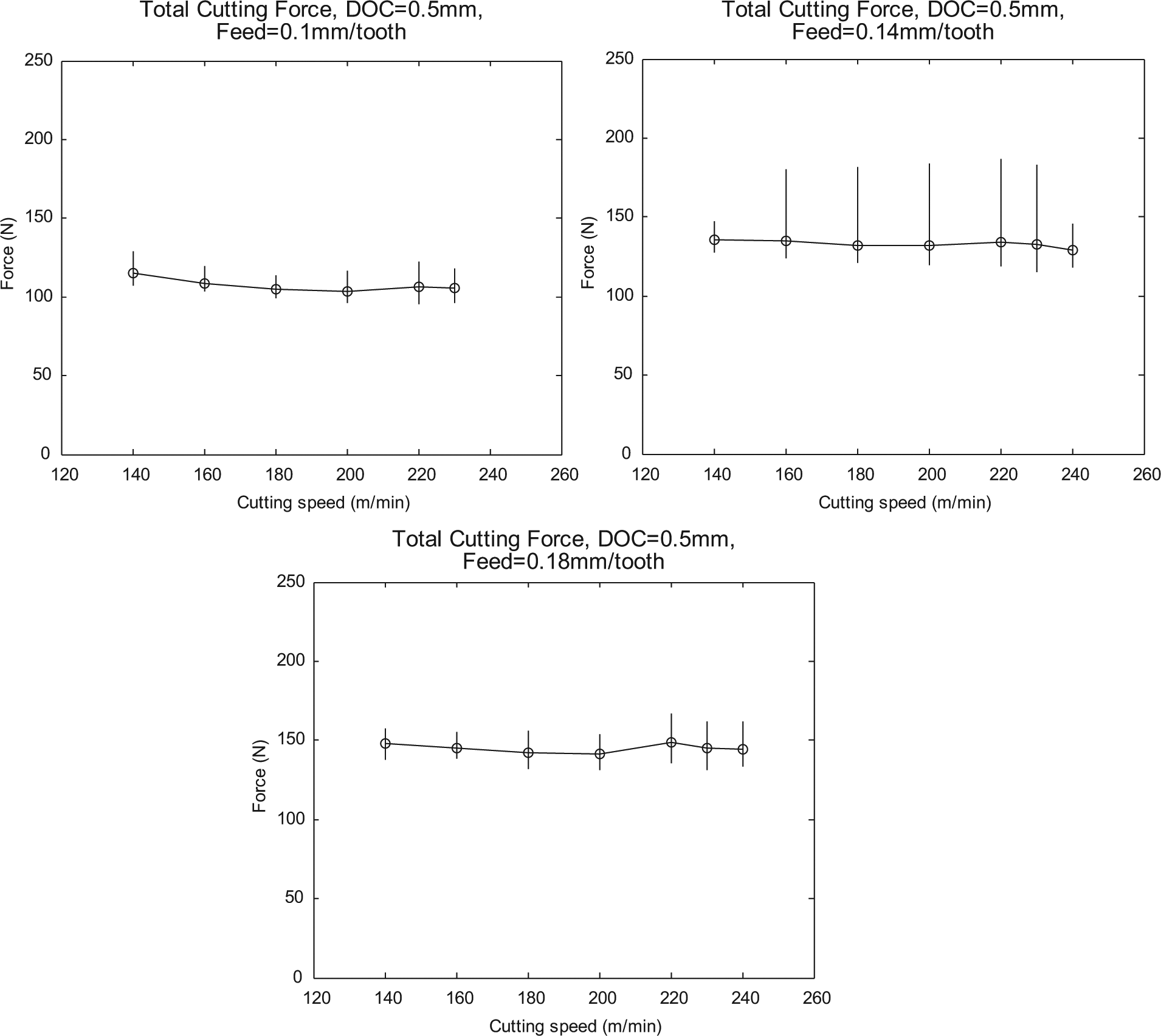
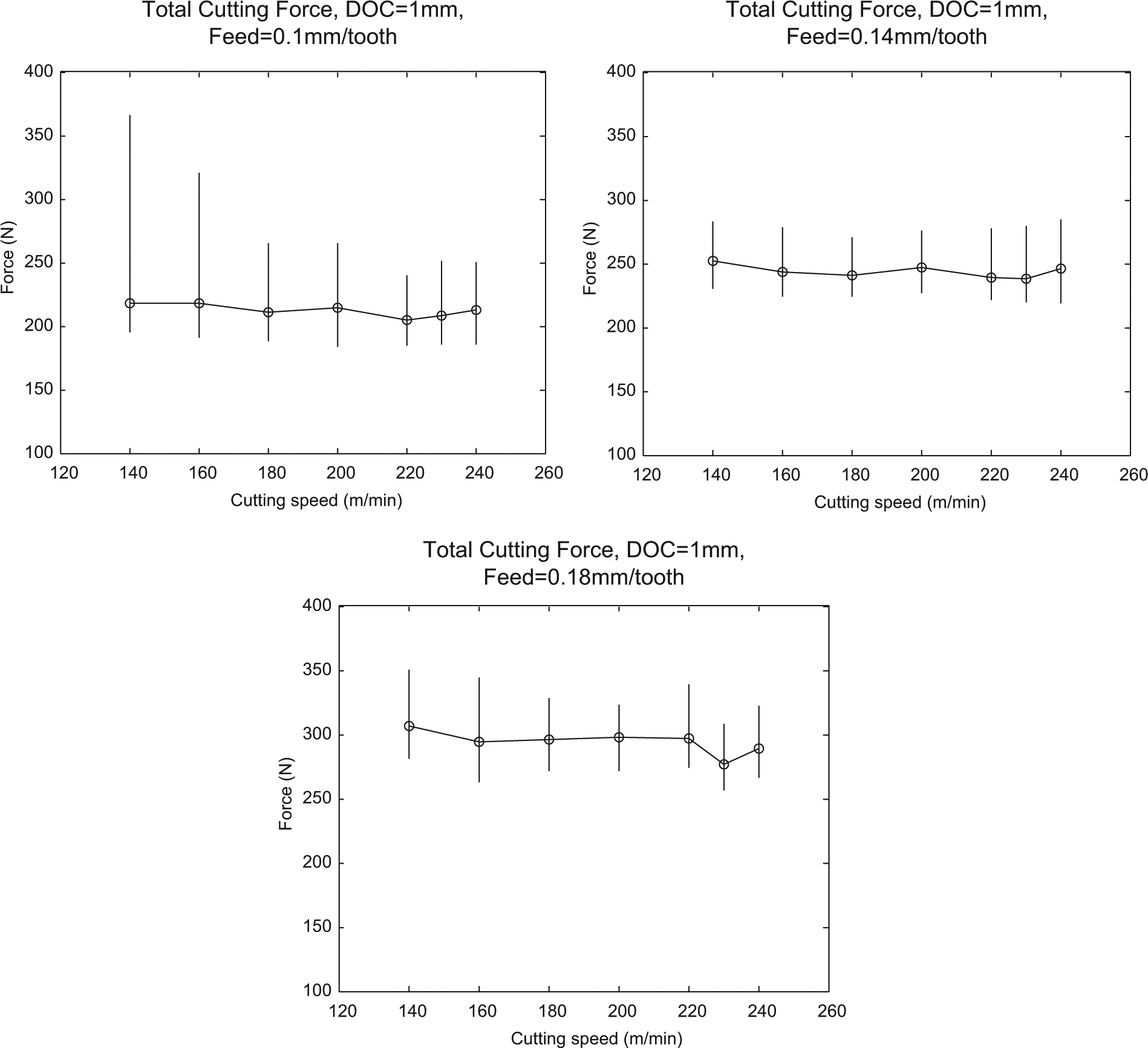
The trend of the averaged peak force (total resultant force) versus the cutting speed is shown in Figure 6, in which Figure 6(a)–(c) corresponds to the axial DOC of 0.5, 1, and 2 mm, respectively. It is clear that with an increase in the feed rate, the cutting forces also increase accordingly. This is due to the fact that a growth in the chip load increases the cutting forces needed to remove the material. It was found that the influence of the cutting speed on the averaged peak cutting force is insignificant within the range of the cutting speed investigated in this study, that is, from 140 to 240 m/min, although there appears to be some fluctuation of the averaged peak forces in the plots. Through a comparison of the plots in Figure 6, it can be seen that the peak forces also increase conformably as a result of the increase in the axial DOC. However, although the chip load was doubled in Figure 6(b) and (c), the corresponding increase in the average peak forces was less than double, which reveals a nonlinearity of the relationship between the chip load and the cutting forces.
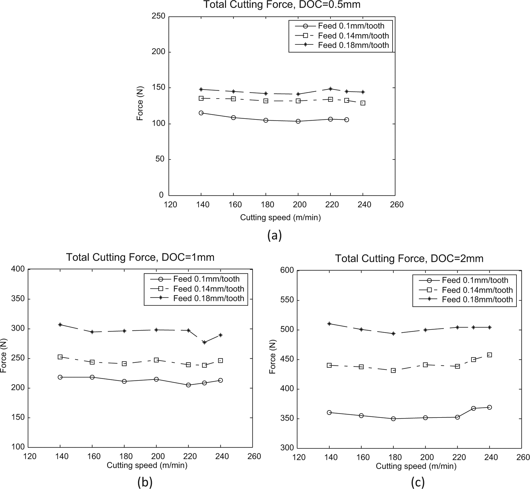
Averaged peak resultant cutting forces, corresponding to axial depth of cut: (a) 0.5, (b) 1, and (c) 2 mm.
Statistical analysis
The aforementioned steady-state cutting phase is under the assumption of homogeneous workpiece material, unvarying cutting parameters, and no severe vibration. In reality, there may be variations of the peak forces in each cutter revolution along with the cutting process due to different reasons. The dynamic interaction between cutting tool and workpiece in milling can lead to vibration due to the interrupted cutting process. More severely, chatter can occur that will affect the surface significantly. In such a case, drastic peak force variations can be observed, especially in cutting difficult-to-machine materials like nickel-based superalloys. The maximum cutting force can reach a value of more than twice of the averaged peak force. Figure 7 shows the cutting force fluctuation under the cutting condition of feed of 0.14 mm/tooth, axial DOC of 0.5 mm, and cutting speed of 230 m/min. It can be seen that chatter occurred at 3.5–3.9 s. A detailed check of Fx is illustrated in Figure 8. While Figure 8(a) shows an overview of the cutting force in the whole cutting pass, Figure 8(b) presents details of the force waveform in a few revolutions without the occurrence of chatter, and Figure 8(c) displays the waveform when chatter occurred. In cutting force assessment, it is necessary to understand such significant peak force variation and to be able to evaluate the associated impacts on the machined surface quality. This is through characterizing the location and variability of the peak force values.
Cutting force waveforms with distinct fluctuation.
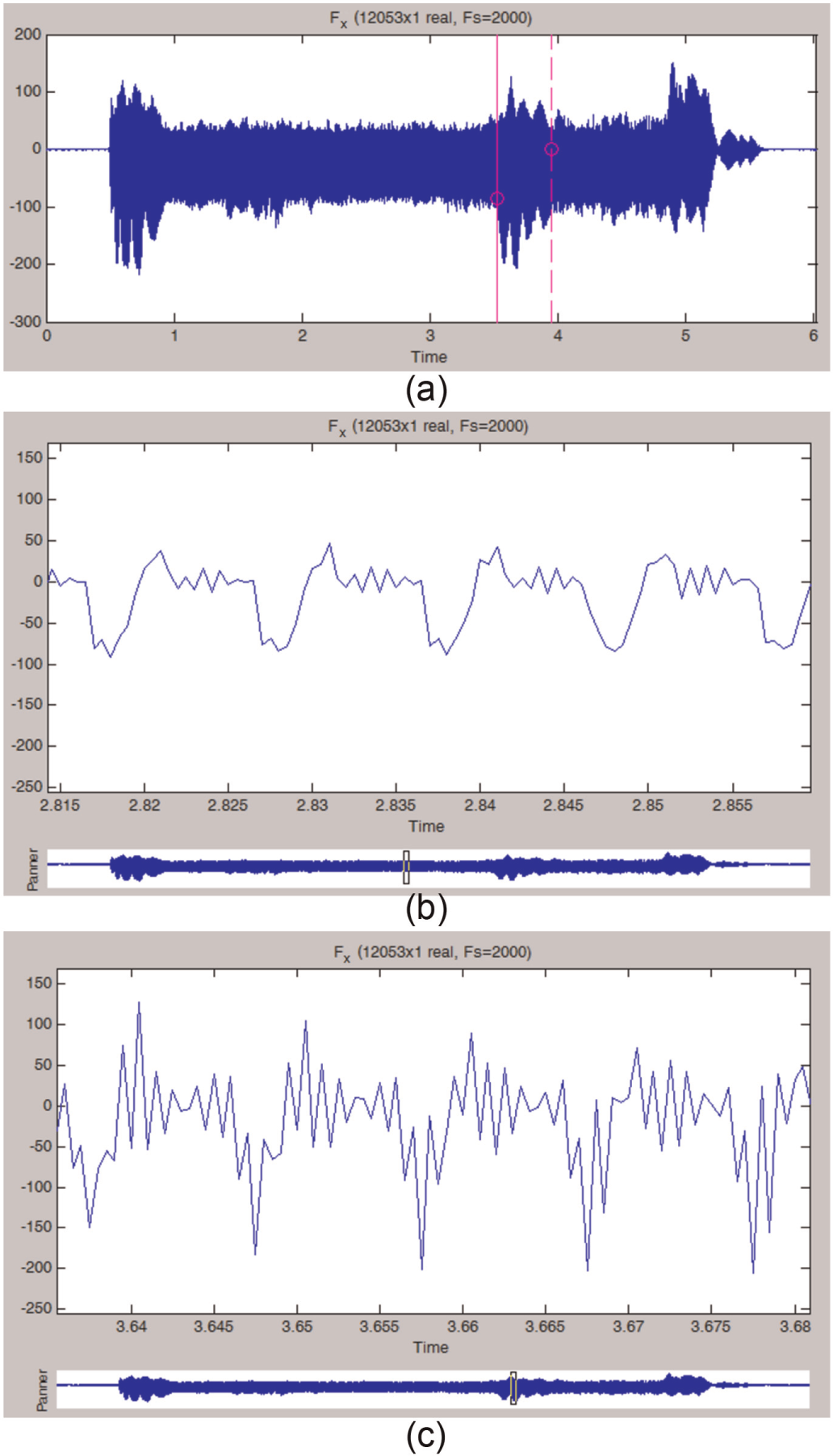
(a) Overview of the cutting force in Fx as shown in Figure 7, (b) zoomed force waveform in stable cutting (zone A) and (c) zoomed force waveform when chatter occurred (zone B).
Time domain statistical parameters can be used to characterize the variation of peak cutting force. Figures 9–11 illustrate the variation range of the resultant total peak forces corresponding to different cutting conditions. The vertical lines show the detected peak range within a boundary of the maximum and minimum, and the small circles label the averaged peak forces. It is evident that the fluctuation of the peaks can be significant. The variation of the peak force values is up to 20% of the average peaks or even higher.
Variation range of the resultant total peak forces, axial DOC of 0.5 mm.
Variation range of the resultant total peak forces, axial DOC of 1 mm.
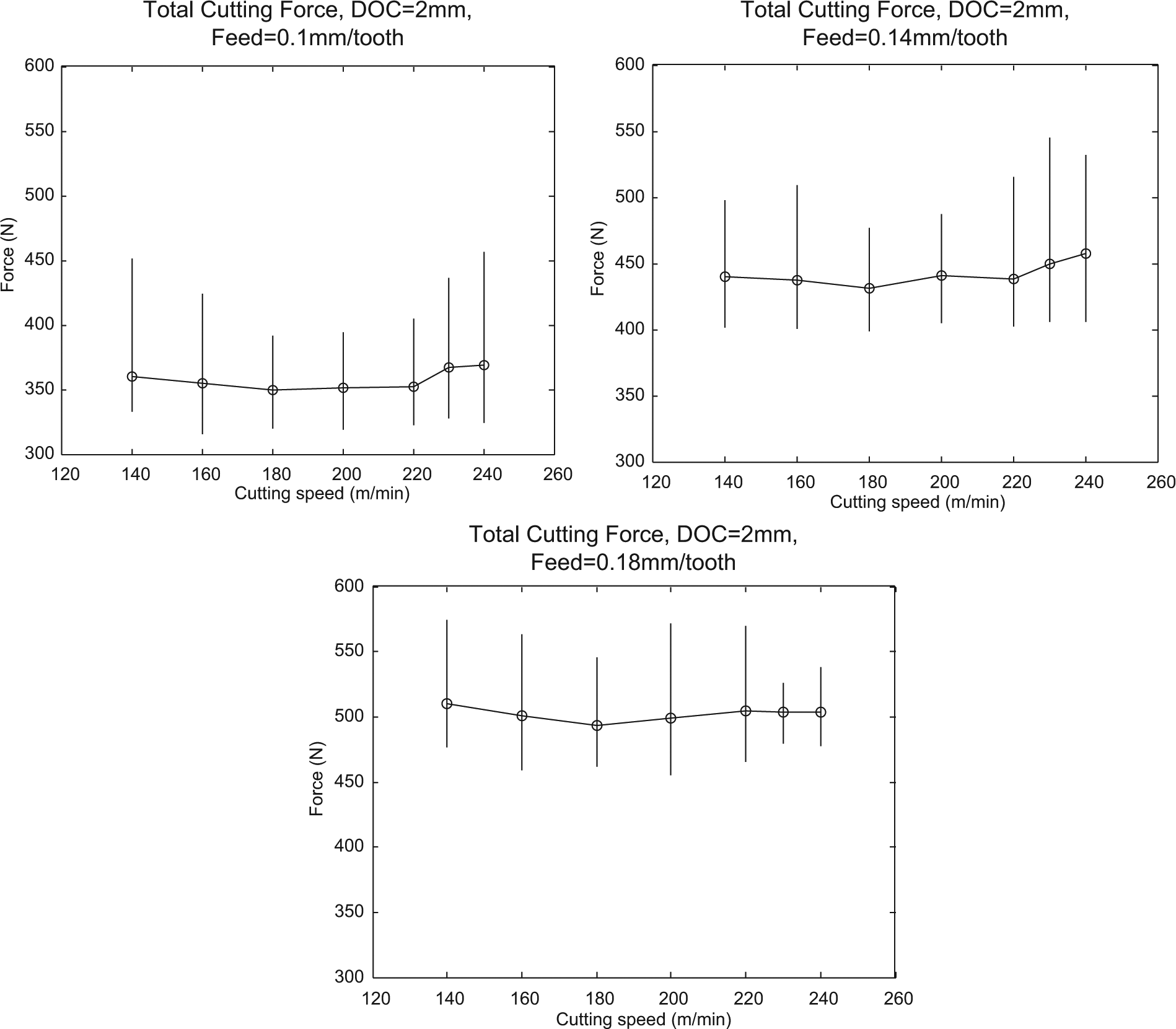
Variation range of the resultant total peak forces, axial DOC of 2 mm.
Figure 12 presents histograms of peak force values in steady cutting stages corresponding to two different cutting conditions: feed of 0.1 mm/tooth, axial DOC of 1 mm, and cutting speed of 140 m/min in Figure 12(a), and feed of 0.14 mm/tooth, axial DOC of 1 mm, and cutting speed of 200 m/min in Figure 12(b). The distribution of the peak forces in each revolution of the cutting tool along the x, y, and z directions and the resultant total peak forces are represented graphically. It is noted that they are not normal distributions. Instead, they are significantly right-skewed distributions. Right-skewed data often occur due to lower bounds on the data. Corresponding to the chip load, there is a lower limit of the peak cutting force on the left side of the distribution. The distribution’s peak is off center toward the limit, and a tail stretches away from it. Although the cutting condition in this case is regarded stable, there are large peak force values, as shown in the considerable long right tail of the histogram. It is interesting to see that under the cutting condition of feed of 0.14 mm/tooth, axial DOC of 1 mm, and cutting speed of 200 m/min, the skewness of the distribution of the peak force values became slack, as shown in Figure 12(b).
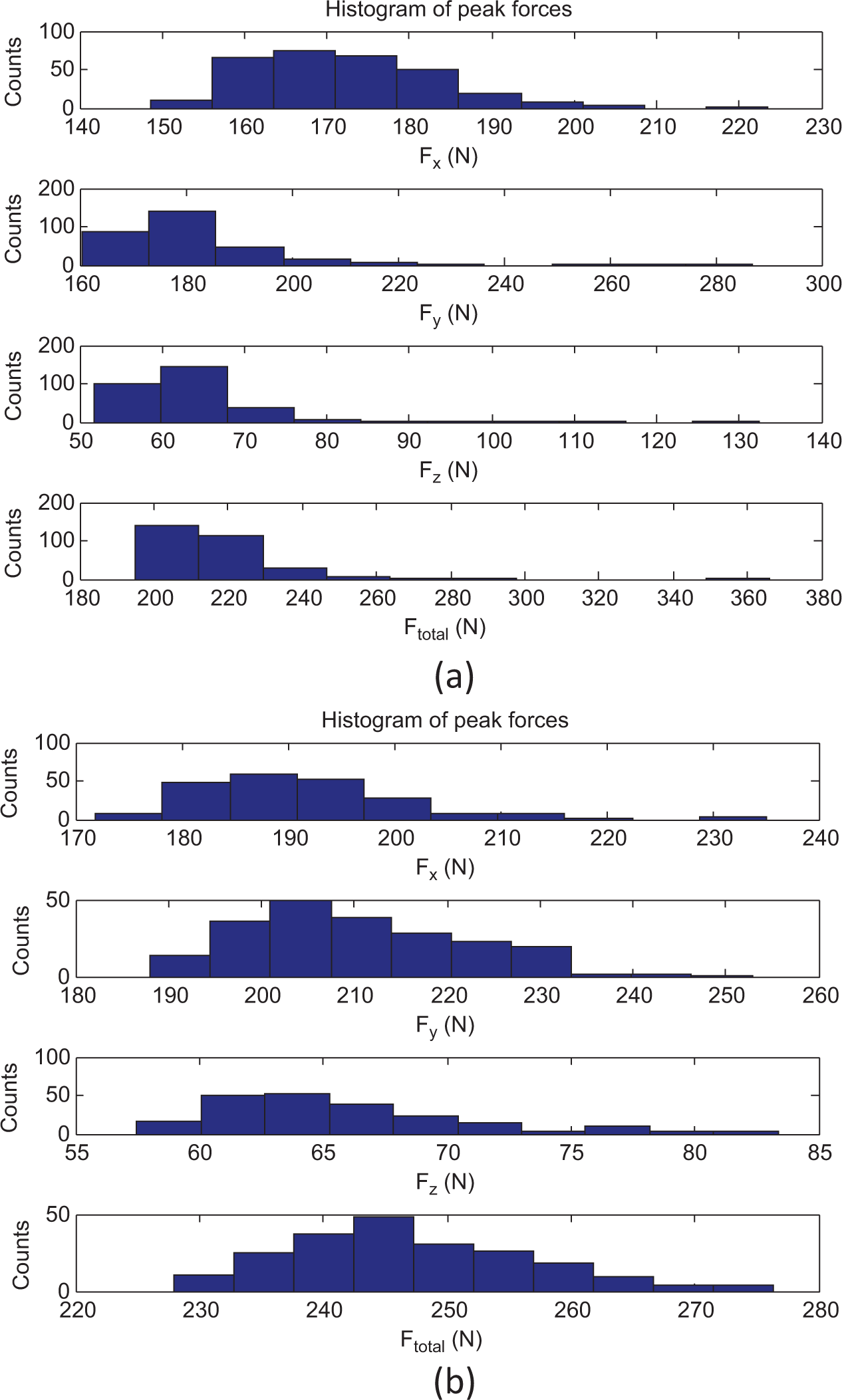
Histogram of the peak force values in the steady cutting stage. Cutting condition: (a) feed of 0.1 mm/tooth, axial depth of cut 1 mm, and cutting speed of 140 m/min; (b) feed of 0.14 mm/tooth, axial depth of cut 1 mm, and cutting speed of 200 m/min.
In view of the skewness, using only the statistical mean and standard deviation is not enough to characterize the peak force distribution. Statistical parameter skewness can be used to measure the asymmetry of a distribution. It is in fact the third moment about the mean of the distribution, which is given by
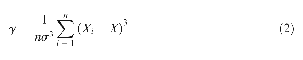
where σ is the standard deviation, Xi is the peak force value in different cutter revolutions,
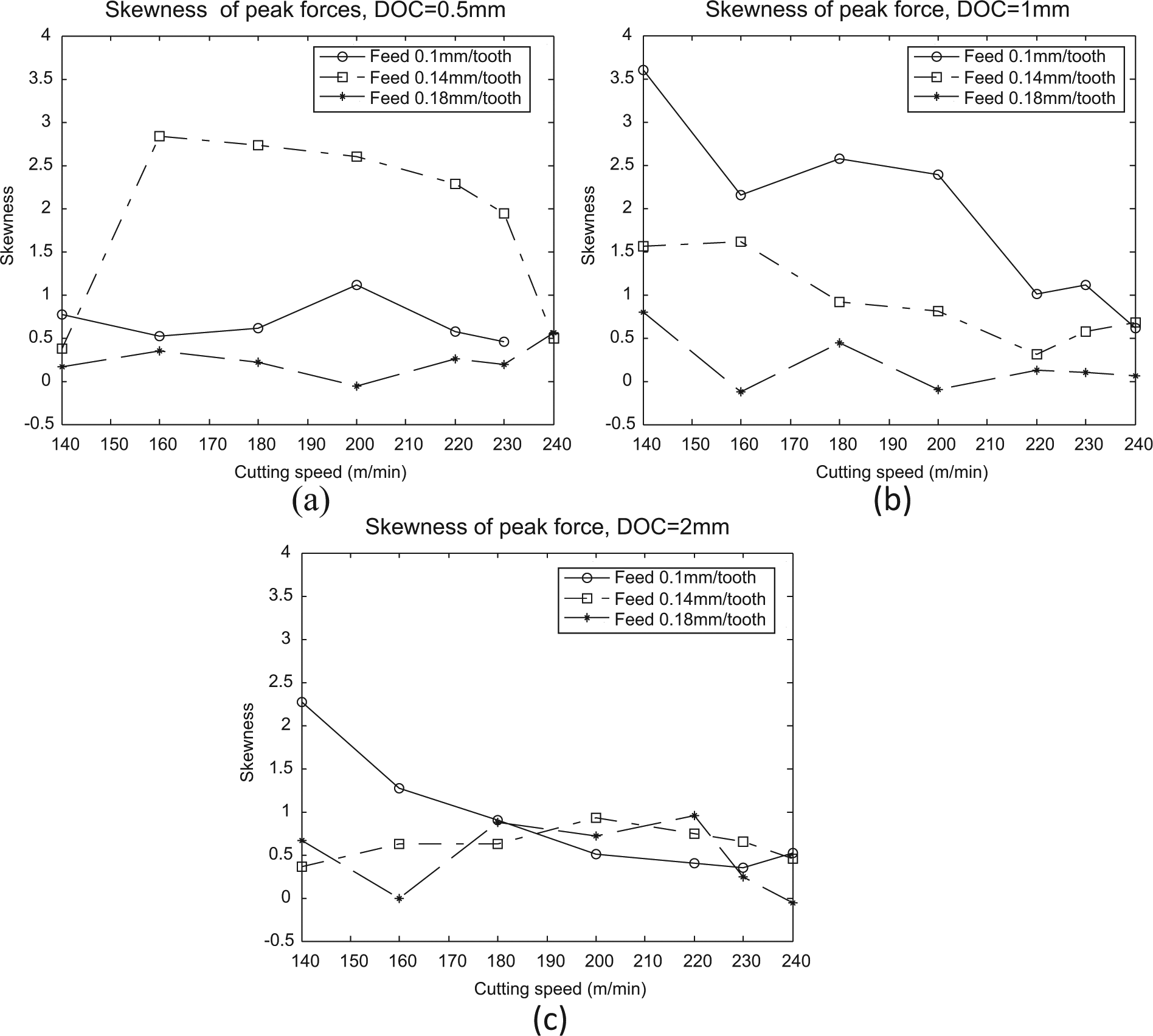
Skewness of the peak total forces, corresponding to DOC: (a) 0.5, (b) 1, and (c). 2 mm.
Wavelet analysis
Signals with sharp changes and local features might be better analyzed with wavelet transform. The wavelet transform compares a signal with a set of template functions obtained from the scaling and shift of a base wavelet to look for their similarities, thus enables variable window sizes in analyzing different frequency components within a signal. 16 A wavelet is a waveform of effectively limited duration that has an average value of 0. Wavelet analysis is capable of revealing aspects of data such as trends, breakdown points, self-similarity, and so on. It can provide a different view of data than those presented by traditional techniques like the Fourier analysis.
The continuous wavelet transform (CWT) of a real signal x(t) is defined with respect to an analyzing wavelet ψ(t), which is complex in general, as
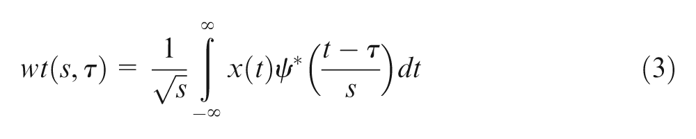
where s > 0 represents the wavelet scaling parameter, which has clearly a relationship with frequency. The symbol τ is the shifting parameter, which translates the scaled wavelet along the time axis. The symbol ψ* denotes the complex conjugate of the base wavelet ψ(t). A large number of wavelet families exist. The Haar wavelet and the Daubechies wavelet are among the most widely used. By varying the values of the scaling parameter and the shifting parameter, a series of wavelet coefficients can be obtained.
The discrete wavelet transform (DWT) calculates only a subset of the possible scales, in which scales and positions are chosen based on powers of 2; thus, the analysis will be much more efficient. A one-stage DWT with a two-channel subband coder is actually a filtering algorithm with two complementary filters: a low-pass filter and a high-pass filter. Passing through it, the original signal will emerge as two signals. The approximations are the high-scale, low-frequency components of the signal. The details are the low-scale, high-frequency components.
For the cutting force signals, the low-frequency components represent the force variation due to the fundamental cutting mechanics such as tool rotation and chip load variation, and the high-frequency components illustrate the process dynamics such as tool–workpiece vibration and some nonstationary events such as the sudden breakage of tool or a crack. To demonstrate the application of DWT on assessment of the dynamic effects in the cutting process, for example, a one-level decomposition of the force signal in the x-axis is shown in Figure 14. From the Detail D1 as shown in Figure 14(a), which illustrates the high-frequency components of the cutting force Fx, it can be seen that the dynamic effects at the cutter entry stage and exit stage are significant. As to the steady cutting stage, a zoomed view is given in Figure 14(b). The main dynamic component of the force signal occurs along with the engagement of the cutting edge into workpiece.
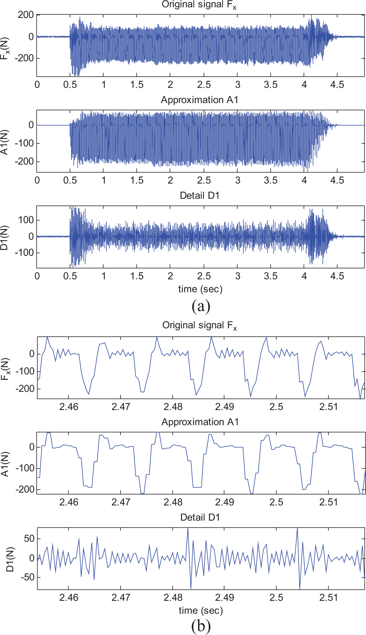
Wavelet decomposition of the force signal (Fx): (a) overview and (b) zoomed view.
The wavelet packet transform (WPT) is a generalization of wavelet decomposition that offers a richer signal analysis. It further decomposes the detailed information of the signal in the high-frequency region. Using the WPT, the time frequency composition of a signal can be determined, thus enables a good understanding of what is contained within the signal. For the assessment of the cutting force signals in milling Inconel 718, WPT can be applied for the detection of chatter occurrence.
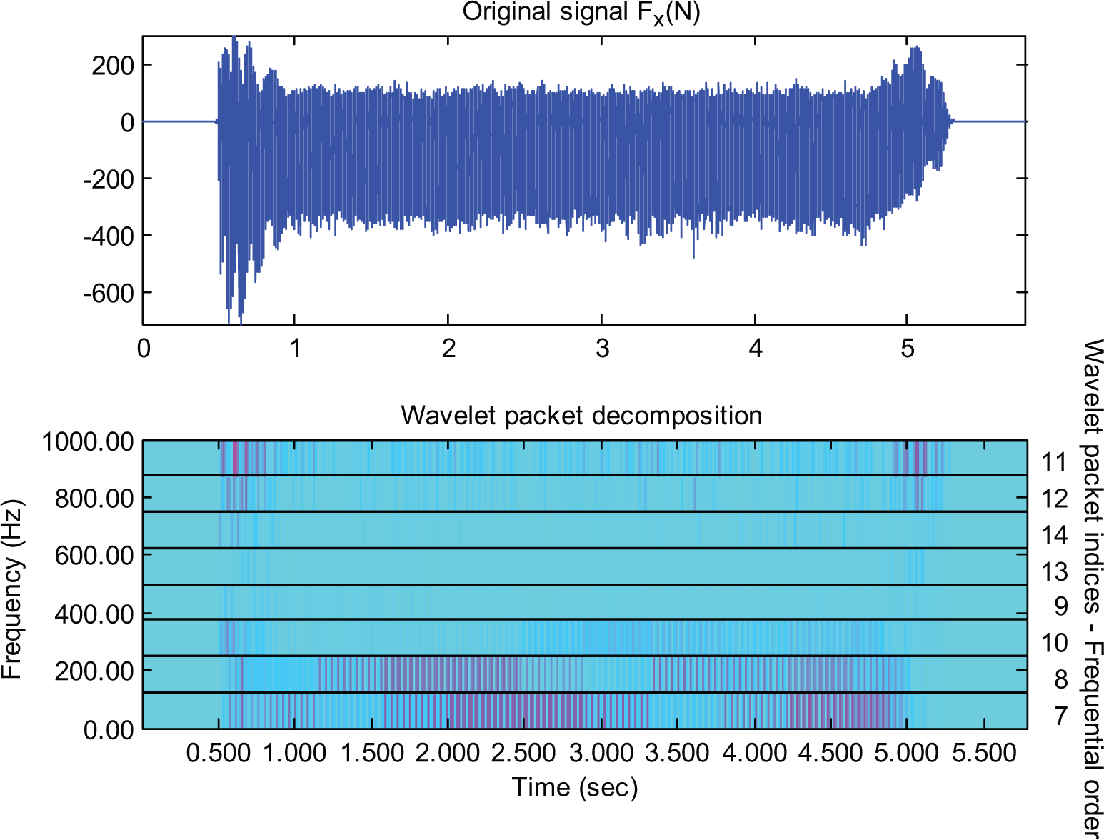
Chatter is a self-induced vibration between tool and workpiece due to the wavy surface regeneration and loss of dynamic stability. It causes poor workpiece quality, rapid tool wear, and noise. Chatter should be prevented from occurring at all times. When chatter occurs, the cutting forces can grow significantly due to the unstable dynamic interaction between tool and workpiece, in which the chatter vibrations can increase to a point when the cutter jumps out of the cut or cracks due to the excessive forces involved. Usually, chatter vibrations occur in end-milling processes when the axial depths of cut are larger than a stability limit allowed by the structural compliance between the tool and the workpiece. However, in this experimental study of milling Inconel 718, it was found that even under light axial DOC such as 0.5 mm, chatter also occurred, which showed strong randomness. Figure 15 presents the WPT results of the cutting force signals to demonstrate the effectiveness for chatter detection. The cutting condition was that feed of 0.14 mm/tooth, axial DOC of 0.5 mm, and cutting speed of 230 m/min. Wavelet packet decomposition at level 3 was conducted using the DB4 wavelet and Shannon entropy. The chatter occurrence at about 3.6 s can be clearly identified in the WPT decomposition, especially in the packet DAA3 (i.e., packet (3,4)). However, when the axial DOC was further increased to 1 and 2 mm, as shown in Figures 16 and 17, respectively, it was found that no chatter occurred in the steady cutting stage. This seems controversial to the traditional chatter theory. It shows that there exists noticeable randomness on the chatter onset condition in terms of cutting parameters, and further research on the cutting dynamics in milling Inconel 718 is needed.
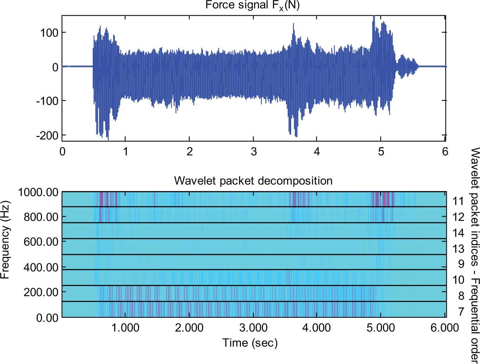
WPT results of the cutting force signals with chatter occurrence (cutting condition: feed of 0.14 mm/tooth, axial depth of cut of 0.5 mm, and cutting speed of 230 m/min).
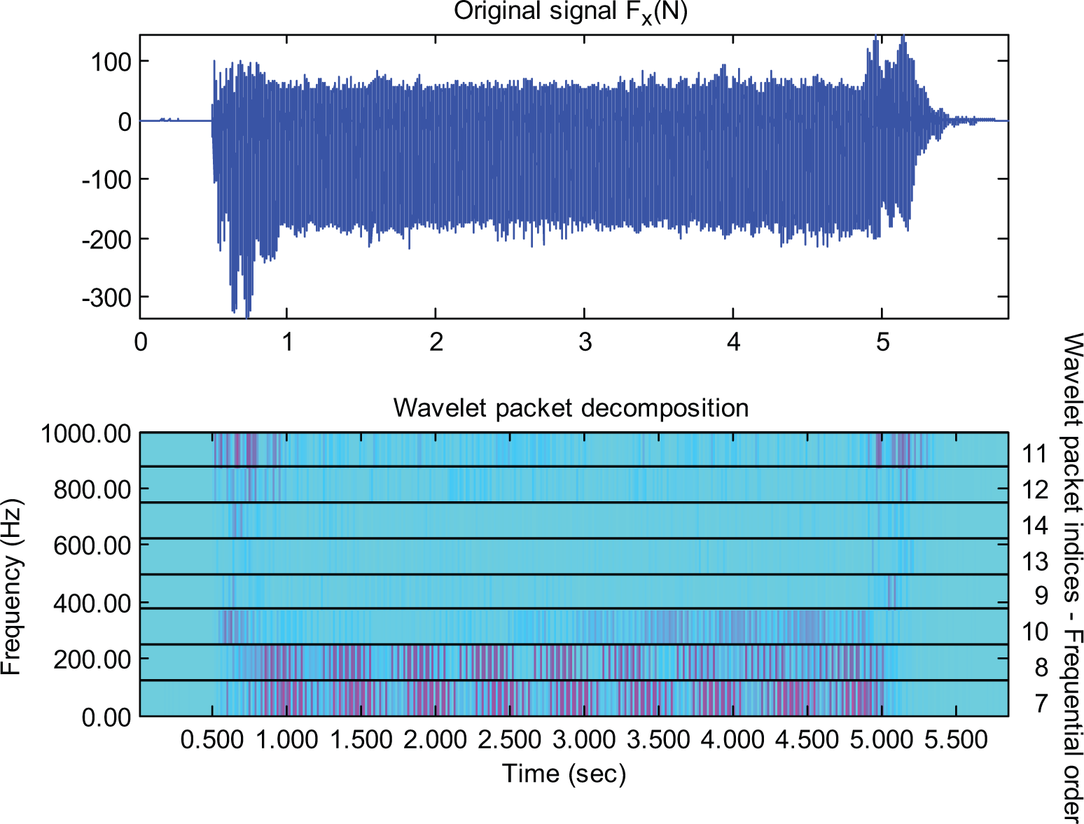
WPT decomposition of the cutting force signals (cutting condition: feed of 0.14 mm/tooth, axial depth of cut of 1 mm, and cutting speed of 230 m/min).
WPT decomposition of the cutting force signals (cutting condition: feed of 0.14 mm/tooth, axial depth of cut of 2 mm, and cutting speed of 230 m/min).
Conclusion
This article presented an experimental study of the cutting force variation in high-speed dry end milling of Inconel 718 superalloy using a coated carbide insert milling cutter. The assessment of the cutting force variations was carried out using statistical approaches and wavelet decomposition, so that the dynamic effects have been taken into consideration, including the averaged peak force values, the peak force range and distribution, and the skewness, to arrive at the following conclusions:
It is proposed that the averaged peak force values be used to evaluate the effect of cutting parameters on the cutting forces. It has been shown that the averaged peak cutting forces increase with an increase in the chip load in a nonlinear way, but cutting speed does not show a significant influence on the averaged peak cutting force for the range of cutting speeds tested in this study.
A significant variation of the peak forces in each tool revolution has been observed under different cutting conditions. Mostly, the distribution of the peak forces was not normal. Instead, they were significantly right-skewed distributions. An assessment of the skewness values for the peak resultant forces showed that a lighter chip load (in terms of feed per tooth and DOC) resulted in a higher skewness value, which indicated a longer tail on the right side. With the increment of the cutting speed, there appeared to be a decrease of the skewness values.
It has been demonstrated that wavelet transform is an effective tool to analyze the dynamic effects in the cutting force signals. The examination of the Details in DWT for the high-frequency components of cutting forces showed that the dynamic interaction or vibration at the cutter entry stage and exit stage was most significant. The wavelet packet transform decomposition was applied for the detection of chatter occurrence in the force signals. It has been shown that wavelet packet decomposition at level 3 with the DB4 wavelet and Shannon entropy was effective to identify the chatter onset. The results also indicated some randomness in the chatter onset condition in terms of cutting parameters.
Footnotes
Declaration of conflicting interests
The authors declare that there is no conflict of interest.
Funding
This research received no specific grant from any funding agency in the public, commercial, or not-for-profit sectors.