
Abstract
This study makes a comparison between whisker-reinforced alumina and SiAlON ceramic tools in high-speed face milling of Inconel 718. A series of tests have been conducted, and the cutting forces, tool wear morphologies and tool failure mechanisms are discussed with regard to a wide range of cutting speeds (500–3000 m/min). Results show that the resultant cutting force of SiAlON ceramic tool KY1540 is much bigger than that of whisker-reinforced alumina ceramic tool KY4300 at the same cutting condition. For both kinds of tools, under relatively lower cutting speed, nose notch wear is the predominant failure mode affecting the tool life, while further increase in the cutting speed, notch wear at the depth of cut becomes the determining factor. KY1540 shows a better notch wear and thermal shock resistance than KY4300. The tool failure mechanisms involve notching, microcracks, chipping, flaking, adhesion and oxidation wear. Better surface quality can be got using KY4300 ceramic tools.
Introduction
High-speed machining technology, leading to lower cutting forces, higher removal rates and therefore to lower energy consumption, is one of the important aspects of advanced manufacturing technology. It is introduced to achieve high productivity and save machining cost.1,2
Inconel 718, a nickel-based superalloy, which contains a niobium age-hardening addition, has been widely used in the aircraft and nuclear industry due to its exceptional thermal resistance and the ability to retain its mechanical properties at elevated temperatures over 700 °C. 3 However, it is well known as a difficult-to-cut material considering its high shear strength, work-hardening tendency, strong tendency to weld, low thermal conductivity and so on.4–6 The tendency to maintain its high strength at the elevated temperature makes it especially hard to machine at high cutting speed.
Cemented carbide tools and coated carbide tools are still largely used for machining the nickel-based superalloys, especially Inconel 718. However, the cutting speed is limited in the order of 50 m/min, and it goes against the aim to achieve fast material removal and better surface quality.1,2,7 High temperature resistance, hot hardness and low chemical affinity enable the ceramic tools to be used to machine Inconel 718 at high cutting speeds.1,8 Many researchers have investigated the cutting performance of ceramic tools when machining Inconel 718 at high cutting speeds. Li et al. 2 used three kinds of SiAlON grade inserts for high-speed turning tests of Inconel 718 and concluded that SiAlON ceramic tools are prone to notch wear at lower speeds while further increasing the speed to 300 m/min leads to a reduction in notching and an increase in nose and flank wear. Altin et al. 8 studied the effects of cutting speed on tool wear when turning Inconel 718 with silicon nitride-based and whisker-reinforced ceramic tools with different geometries and recommended KYON 4300 square-type tool inserts for the cutting of Inconel 718 at low cutting speeds and KYON 2000 round-type tool inserts at high cutting speeds. Zheng et al. 9 studied wear mechanisms during high-speed turning of Inconel 718 alloy with SiAlON cutting tools and found that the main wear mechanisms are adhesive wear and abrasive wear. Vagnorius and Sorby 10 studied the effect of high-pressure cooling on life of SiAlON tools when turning Inconel 718. Xiao et al. 11 established a notch wear model of ceramic tool in high-speed machining of nickel-based superalloy. Coelho et al. 12 studied the effects of cutting edge preparation and geometric modifications of Al2O3-based and Al2O3-based + SiCw ceramic tools when turning Inconel 718 at high cutting speeds. It can be seen that previous studies of ceramic tools when machining Inconel 718 concentrate mainly on turning tests and the cutting speeds are limited. Little work has been done regarding the performance of ceramic tools in high-speed face milling of Inconel 718. To further increase the productivity, there is a need for further research into the cutting performance and wear mechanisms of ceramic tools in high-speed face milling of Inconel 718.
This article presents an experimental study on high-speed face milling of nickel-based superalloy Inconel 718 with two kinds of ceramic tools under dry cutting condition. The cutting forces and tool wear mechanisms under different cutting speeds are investigated and discussed. Surface roughness is analyzed as well. The results of this study would be useful in understanding the cutting performance and wear mechanisms of whisker-reinforced alumina and SiAlON ceramic tools in high-speed face milling Inconel 718.
Experimental details
Experimental setup
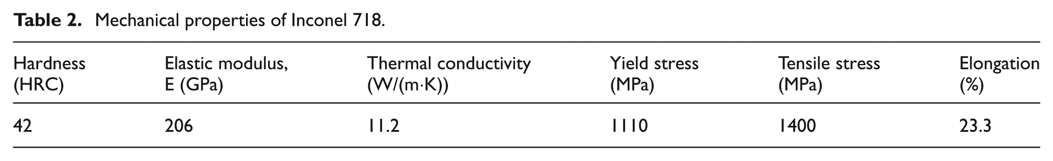
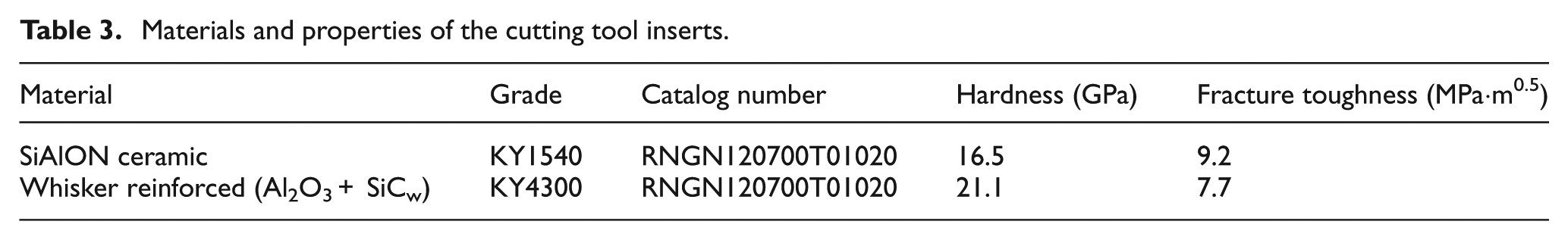
In the present study, the workpiece was solution treated and aged with Nickel-based superalloy Inconel 718. The width and length of workpiece block were 75 and 100 mm. The chemical composition and mechanical properties of Inconel 718 used in the experiments are given in Tables 1 and 2, respectively.
Chemical composition of Inconel 718 (wt%).
Mechanical properties of Inconel 718.
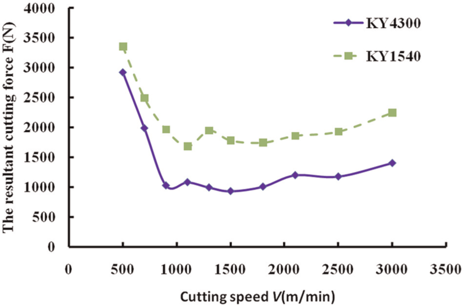
Two kinds of round ceramic inserts, KY1540 SiAlON and KY4300 whisker-reinforced alumina, were used in the milling tests. Materials and properties of the cutting tool inserts are shown in Table 3. Vickers’ indentation tests, 13 performed on a Vickers’ hardness tester (Model HV-120; China) with a load of 196 N and a holding time of 15 s, were used for the calculations of fracture toughness and hardness of the ceramic tools. The cutter was KSSR160RN12CF09 with a maximum diameter of 160 mm, and it is capable of carrying nine inserts. In each milling test, only one insert was mounted on the cutter to maintain constant cutting conditions. All the tests were conducted on a vertical computer numerical control (CNC) machining center DAEWOO ACE-V500 with a spindle speed range from 80 to 10,000 r/min and a 15-kW drive motor.
Materials and properties of the cutting tool inserts.
Experimental procedure
As recommended by the tool supplier, the milling tests were conducted in the type of up-milling operation under dry condition. The feed per tooth fz, axial depth of cut ap and radial depth of cut ae were fixed at 0.08 mm/min, 1 mm and 20 mm, respectively. A wide range of cutting speed from 500 to 3000 m/min was used in the tests. For each experiment, the metal removal volume was fixed at 1500 mm3. A new cutting edge was used in each cutting speed to ensure the measurement repeatable and fairly comparable. Each test was repeated three times under given cutting conditions.
The cutting forces were measured for each cutting speed by the system consisting of Kistler three-component piezoelectric dynamometer (type 9257A), which was mounted on the machine table, charge amplifier, signal converter and a dedicated computer. The tool failure values and morphologies were examined with an AM413ZT Dino-Lite digital microscope (AnMo Co., Taiwan). A scanning electron microscope (SEM; JSM-6610 LV; Japan) equipped with an energy-dispersive spectroscopy (EDS) was used to analyze the tool failure patterns and failure mechanisms. The roughness of machined workpiece material was measured using a portable surface roughness tester (model TR200; China). The surface roughness value Ra used in this article is the arithmetic mean value of five measurements per sample.
Results and discussion
Cutting forces
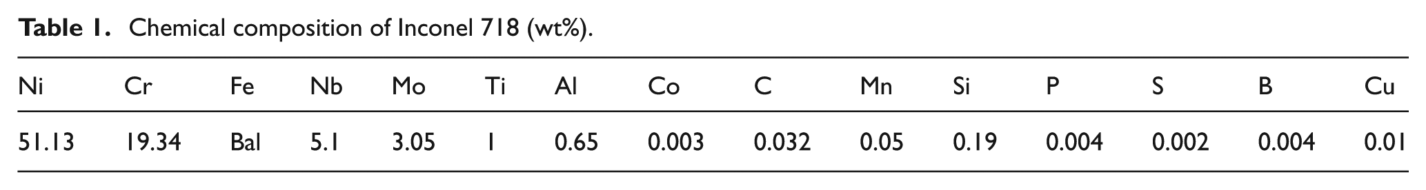
Figure 1 shows the evolution of the resultant cutting force with cutting speed for the two kinds of ceramic tools in high-speed face milling of Inconel 718. To make them comparable, the cutting forces were measured at the beginning of the cutting process under each cutting speed. Obviously, the resultant cutting forces have a tendency to decrease at first and then increase with the increase of cutting speed. When the cutting speeds are relatively low, at 500 and 700 m/min, the cutting temperature is not high enough, and the workpiece material maintains its high hardness in the cutting process. The relatively excessive mechanical shock makes the tool wear seriously, so the resultant cutting forces are very large. With the increase of cutting speed, the cutting temperature reaches a relatively high value, and thermal softening effect leads to the great reduction in hardness of the workpiece material and shear stress in the shear zone. 14 Besides, the shear angle increases because of the thermal softening effect and then gives a shorter shear plane and decreases the shear forces needed for deformation. 15 These factors lead to the decrease of cutting forces. With a further increase in the cutting speed to more than 1800 m/min, the resultant cutting forces have a tendency to increase slowly. Under these cutting speeds, as shown in Figures 2–4, although VB is still relatively small, the increase of VN leads to increase of tool edge radius, which has a significant influence on the increase of cutting force for round inserts. Besides, severe adhesion, oxidation and diffusion wear under the elevated temperature will lead to the rapid drop of the mechanical properties of the cutting tools. Friction between the tools and workpiece material will become more serious. These factors have a greater effect on the cutting force than the thermal softening effect does. And perhaps, this is the reason that leads to the increase of the cutting forces.
Effect of cutting speed on the resultant cutting forces (fz = 0.08 mm/min, ap = 1 mm, ae = 20 mm).
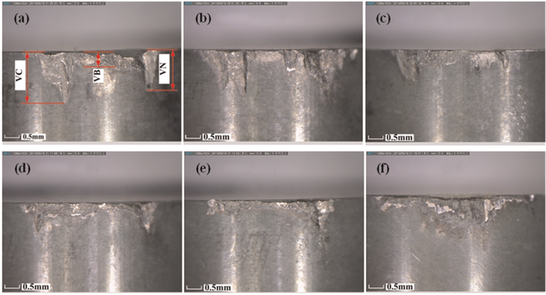
Flank face wear patterns of KY4300 under different cutting speeds (metal removal volume of 1500 mm3): (a) V = 700 m/min, (b) V = 1100 m/min, (c) V = 1500 m/min, (d) V = 2100 m/min, (e) V = 2500 m/min and (f) V = 3000 m/min.
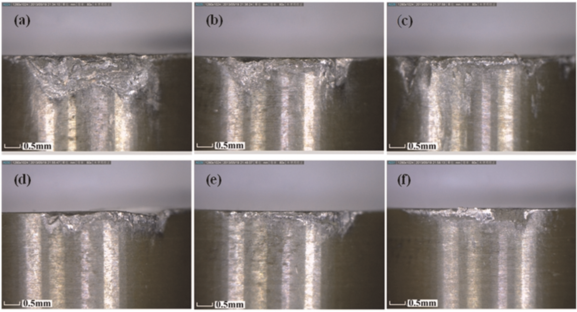
Flank face wear patterns of KY1540 under different cutting speeds (metal removal volume of 1500 mm3): (a) V = 900 m/min, (b) V = 1100 m/min, (c) V = 1300 m/min, (d) V = 1800 m/min, (e) V = 2500 m/min and (f) V = 3000 m/min.
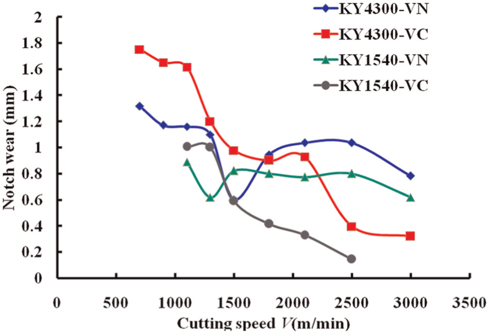
Notch wear values under different cutting speeds (metal removal volume of 1500 mm3).
It is worth to note that the resultant cutting force of KY1540 is much bigger than that of KY4300 at the same cutting speed. This will cause more power consumption.
Tool failure patterns
Figures 2 and 3 present the flank face wear patterns of the two kinds of ceramic tools under different cutting speeds in high-speed face milling of Inconel 718 at fz = 0.08 m/min, ap = 1 mm and ae = 20 mm. It can be seen that the main wear patterns are notch and flank wear. Considering the uneven wear land on the flank face, as shown in Figure 2(a), VC, VN and VB are assigned to stand for notch wear at the tool nose, notch wear at the depth of cut and the mean flank wear width, respectively. VC and VN, which are much bigger than VB, are the main factors that limit the tool life. The evolution of VC and VN values with cutting speed for the two kinds of tools is shown in Figure 4. With the increase of cutting speed, VC has a tendency to decrease while VN, except for 3000 m/min, decreases at first and then increases.
For KY4300 tools, notch wear at the depth of cut VN comes to a minimum value at the cutting speed of 1500 m/min. When the cutting speeds are less than 1500 m/min, VC is bigger than VN, which means VC has a greater influence on tool life than VN. When the cutting speeds are between 1800 and 2100 m/min, they seem to have equal values. With further increase in the cutting speeds to more than 2500 m/min, on the contrary, the influence of VN on tool life is greater than VC. As for KY1540 tools, notch wear has the same trend with KY4300 under different cutting speeds, while VN comes to a minimum value at the cutting speed of 1300 m/min. When the cutting speed is less than 900 m/min, the tools fail because of large area fracture, and there is no typical notch wear, as shown in Figure 3(a). VC has a greater influence on tool life when the cutting speeds are between 1100 and 1300 m/min, while VN has a greater influence on tool life when the cutting speeds are more than 1500 m/min. Especially, when the cutting speed is 3000 m/min, VC seems no longer exists. As shown in Figures 3 and 4, compared with KY4300, VC and VN of KY1540 have a smaller value, and this means that SiAlON ceramic tools have a better notch wear resistance. This is perhaps because of the higher fracture toughness and low coefficient of thermal expansion of SiAlON ceramic tools than Al2O3-based ceramic tools. 16 Adhesion wear of KY1540 seems more serious than KY4300.
At the boundary of the cutting edge, there exists great temperature and stress gradient, which will cause serious thermal and mechanical stress, and this will lead to the formation of notch wear. As shown in Figure 5, chip thickness is changing at different locations of the cutting edge. Chip thickness at the depth of cut is larger than that at the cutting nose, and this will lead to relatively higher cutting temperature at this location. So, under the same cutting speed, cutting temperature has a greater effect on VN. Uncut material, as shown in this figure, is distributed over the machined surface when the tool feeds, and it is plowed toward the cutting edge in the form of side flow. 17 Thus, the uncut material and work-hardening effect have a greater effect on VC. Under relatively low cutting speed, the high cutting forces and strong mechanical shock between the tools and workpiece material make the tools wear serious. So, both VN and VC are large. With the increase of cutting speed, the cutting temperature reaches a rather high value, and thermal softening has a much greater effect on the reduction of the workpiece hardness than it does on that of tool material. The smaller effect of the uncut material and the hard inclusion of the workpiece makes notch wear VC to decrease gradually. However, for VN, higher cutting temperature leads to more serious adhesion and oxidation wear at the notch of depth of cut. The appearance of microcracks accelerates the fracture of the tool material and aggravates notch wear as well. So, VN has a tendency to increase when the cutting speed is more than 1300 m/min for KY1540 and 1500 m/min for KY4300. It is worth to note that when the cutting speed is 3000 m/min, the thermal softening effect makes VN to decrease again.
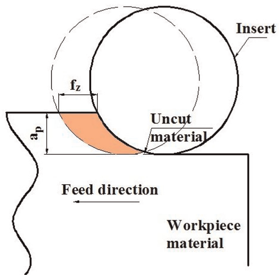
Scheme of changing chip thickness for round cutting tools.
Tool failure mechanisms
As illustrated in section “Tool failure patterns,” when the cutting speed is 1500 m/min for KY4300 and 1300 m/min for KY1540, VN comes to the minimum value. Taking them as the critical cutting speeds, for each kind of cutting tools, the worn tools obtained under three different cutting speeds, that are 700, 1500 and 3000 m/min for KY4300, and 900, 1300 and 3000 m/min for KY1540, are compared and discussed to distinguish the tool wear mechanisms.
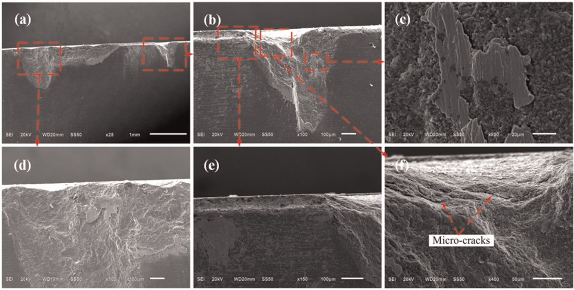
Figures 6 and 7 show the SEM images of worn flank surfaces at V = 700 m/min for KY4300 and V = 900 m/min for KY1540, respectively. It can be seen that the failure types are notching, microcracks, adhesion and abrasion.
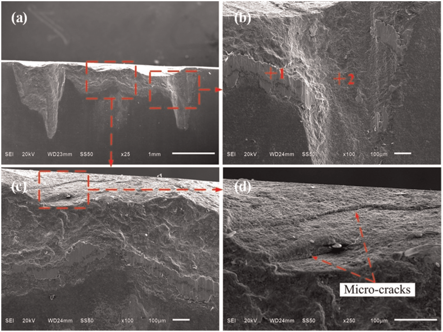
SEM images of flank face of KY4300 at V = 700 m/min.
SEM images of flank face of KY1540 at V = 900 m/min.
Due to the lower hardness of KY1540, as shown in Table 1, the tool fractures more seriously than KY4300 under relatively lower cutting speed. Except notching wear, microcracks occur near the cutting edges (Figures 6(d) and 7(c)), which leads to wear of the flank face and debonding of the rake face, as shown in Figures 8 and 9. It can be seen that the main failure types of rake face are flaking and chipping. It is noticeable that with the increase of cutting speed, flaking has a tendency to decrease. As described in Figure 6(b) and (c), some workpiece material is bonded to the edges of the worn area. At lower cutting speed, unstable built-up edge (BUE) tends to form, leading to pressure welding between chip and tool and workpiece and tool. According to EDS analysis of point 1 in Figure 6(b), as shown in Figure 10, it is enriched in Cr (15.53 wt%), Fe (14.41 wt%) and Ni (44.48 wt%) coming from the workpiece material, while point 2 is enriched in O (31.37 wt%), Al (27.78 wt%) and Si (14.47 wt%) coming from the whisker-reinforced alumina ceramic tool material. It is the evidence of adhesion wear.
SEM images of rake face of KY4300 at V = 500 m/min.
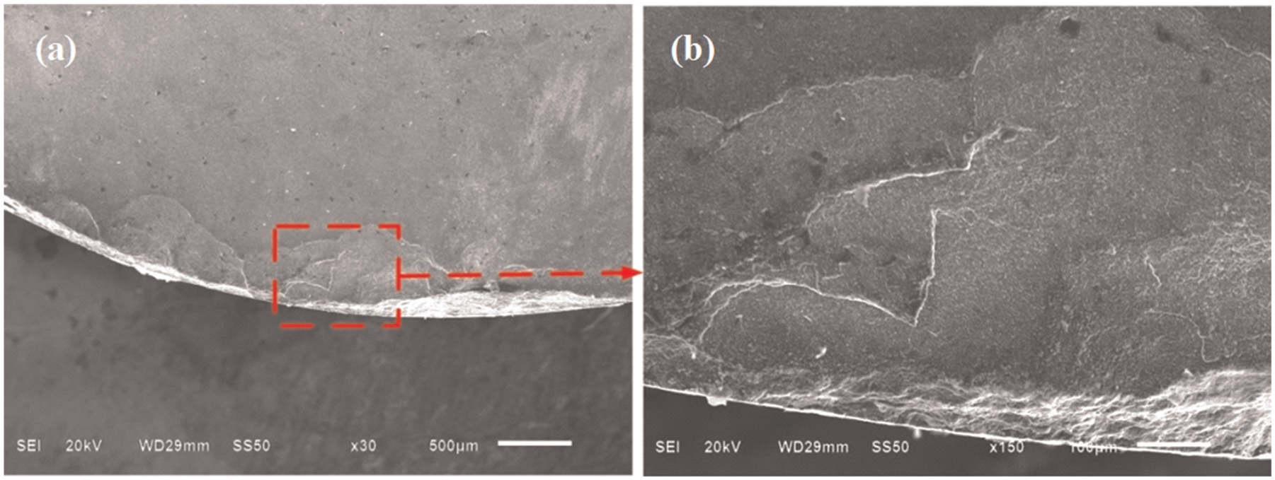
SEM images of rake face of KY4300 at V = 2100 m/min.
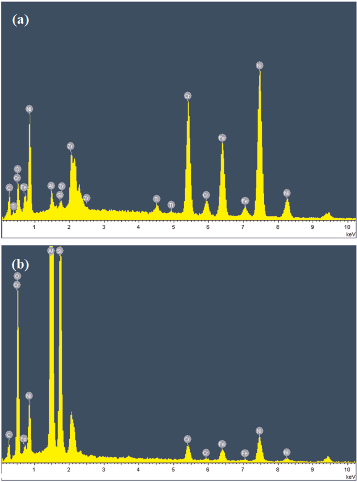
EDS analysis of (a) point 1 and (b) point 2 in Figure 5(b).
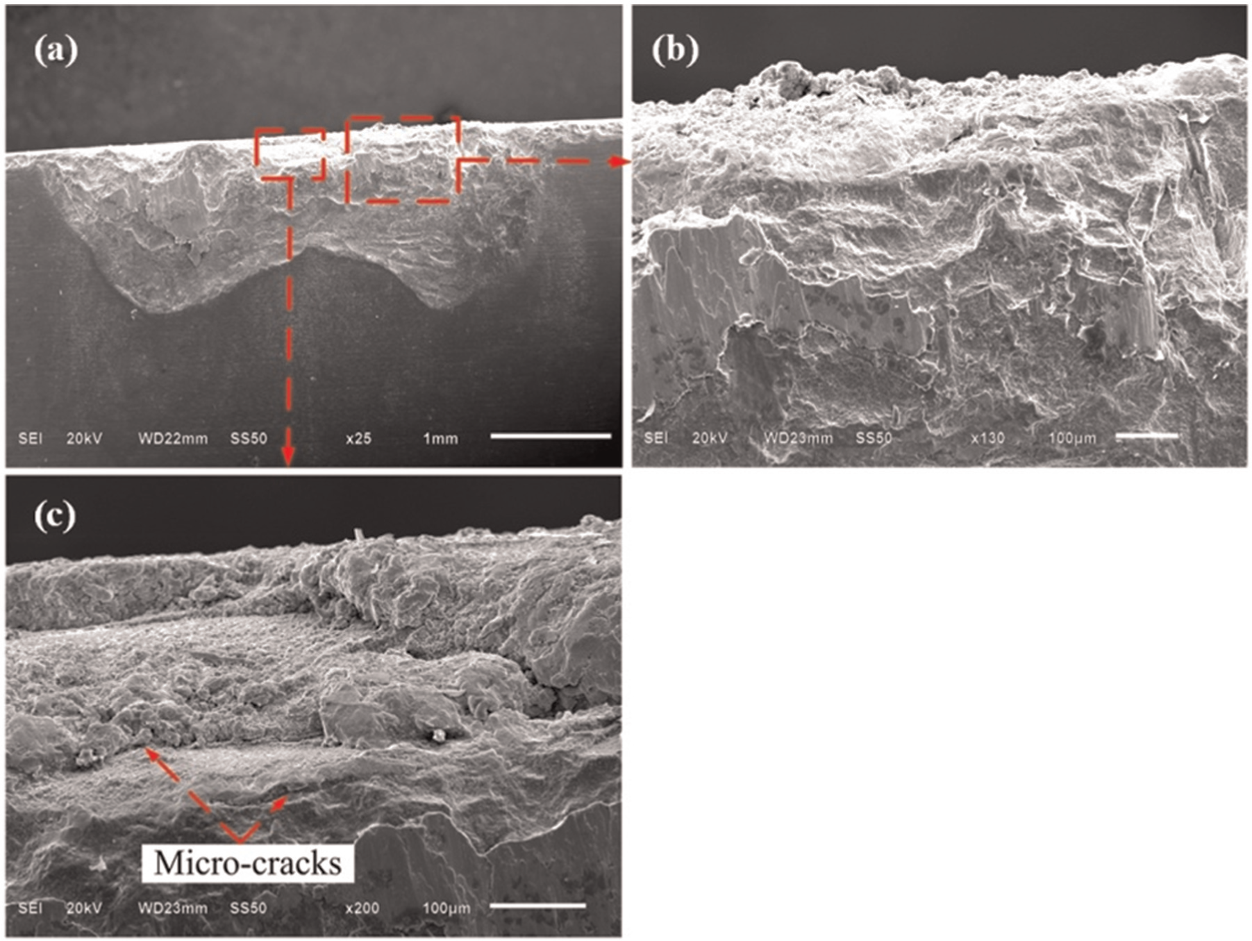
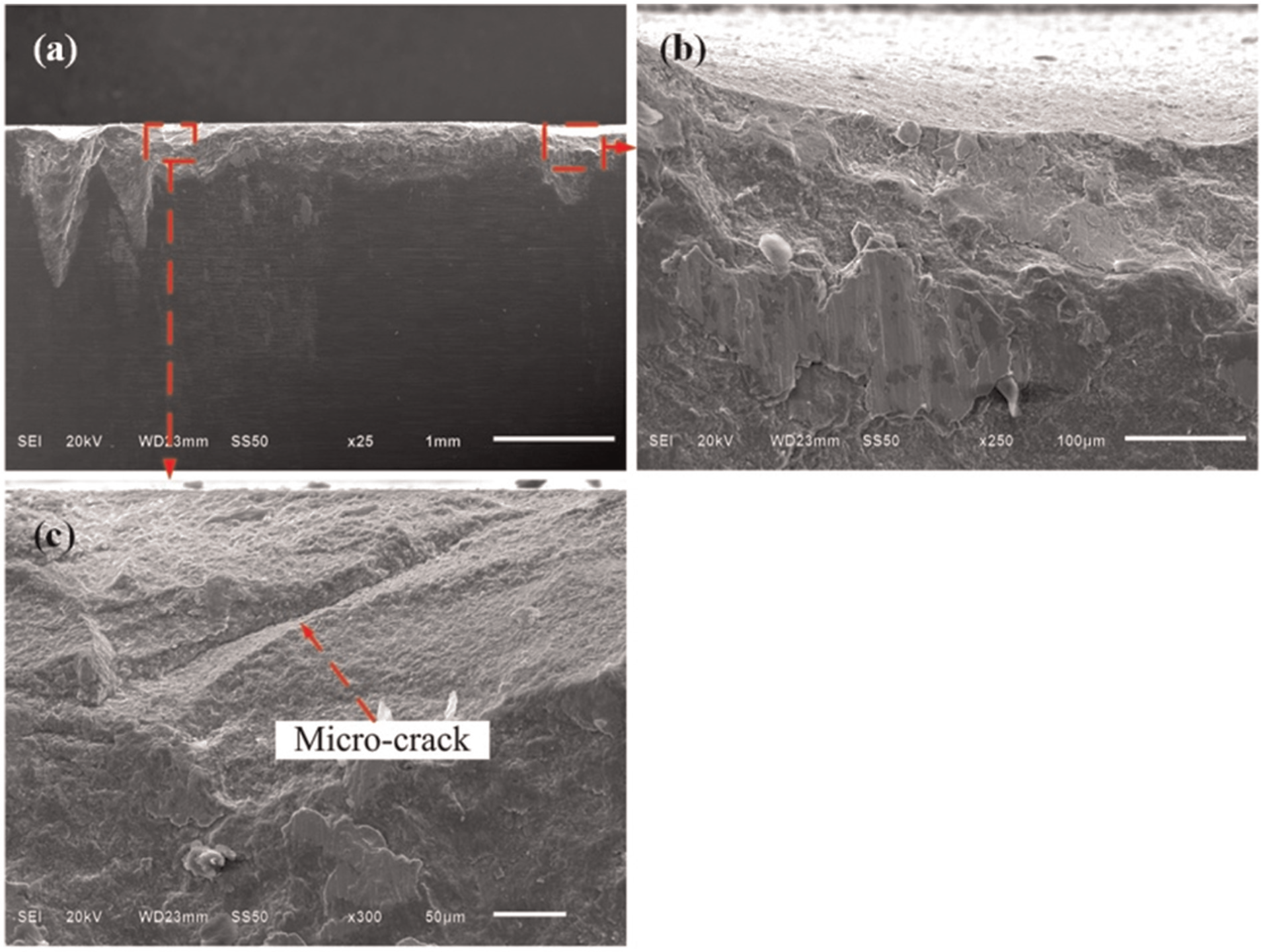
Figures 11 and 12 show the SEM images of worn flank surfaces at V = 1500 m/min for KY4300 and V = 1300 m/min for KY1540, respectively. The failure types are notching, microcracks, adhesion, chipping and abrasion.
SEM images of flank face of KY4300 at V = 1500 m/min.
SEM images of flank face of KY1540 at V = 1300 m/min.
Increasing the cutting speeds to the certain threshold, due to the combination effect of obvious thermal softening and the relatively less severe adhesion and oxidation wear at the location of depth of cut, VN comes to the minimum value. Comparing with the notch at the cutting nose, adhesion at the notch of the depth of cut is more serious (see Figures 11(b) and (d) and 12(b) and (c)). Since adhesion generally increases with the increasing cutting temperature, it confirms the fact that the cutting temperature at the depth of cut is higher. Besides, the large compressive and shear stresses near the cutting tool edge lead to edge chipping, and severe thermal and mechanical stresses lead to microcracks.
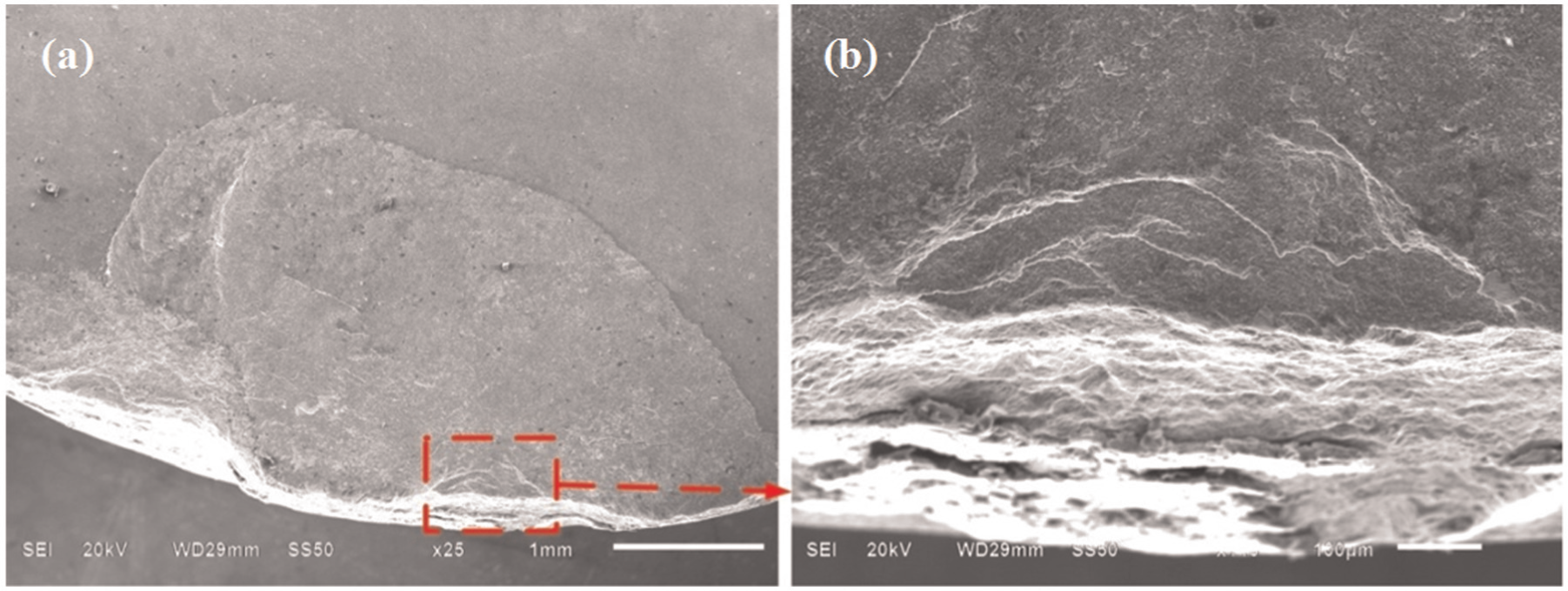
Figures 13 and 14 show the SEM images of flank face of KY4300 and KY1540 ceramic tools after milling of Inconel 718 when cutting speed is 3000 m/min. It can be seen that the failure types involve microcracks, adhesion, chipping and abrasion.
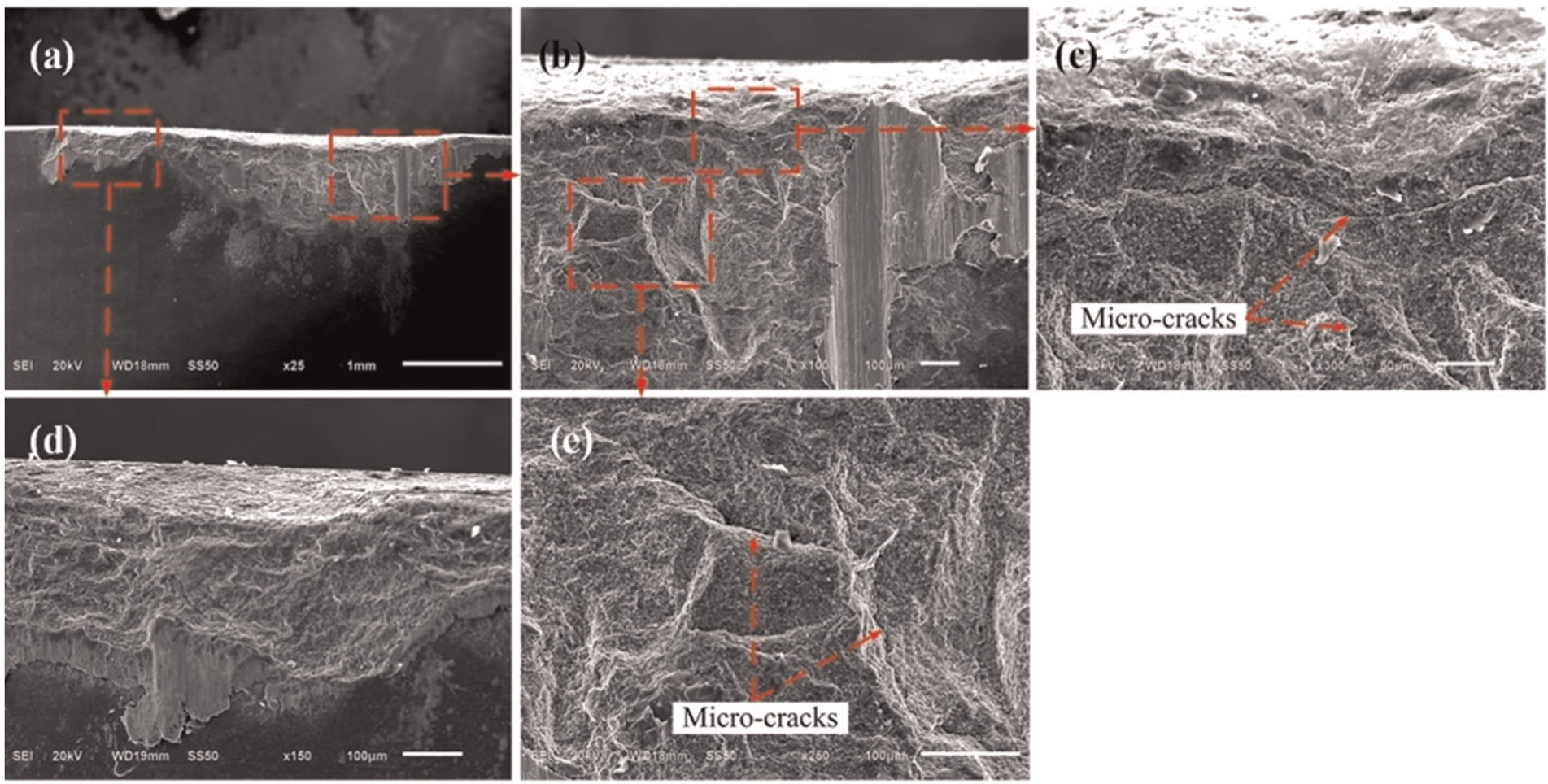
SEM images of flank face of KY4300 at V = 3000 m/min.
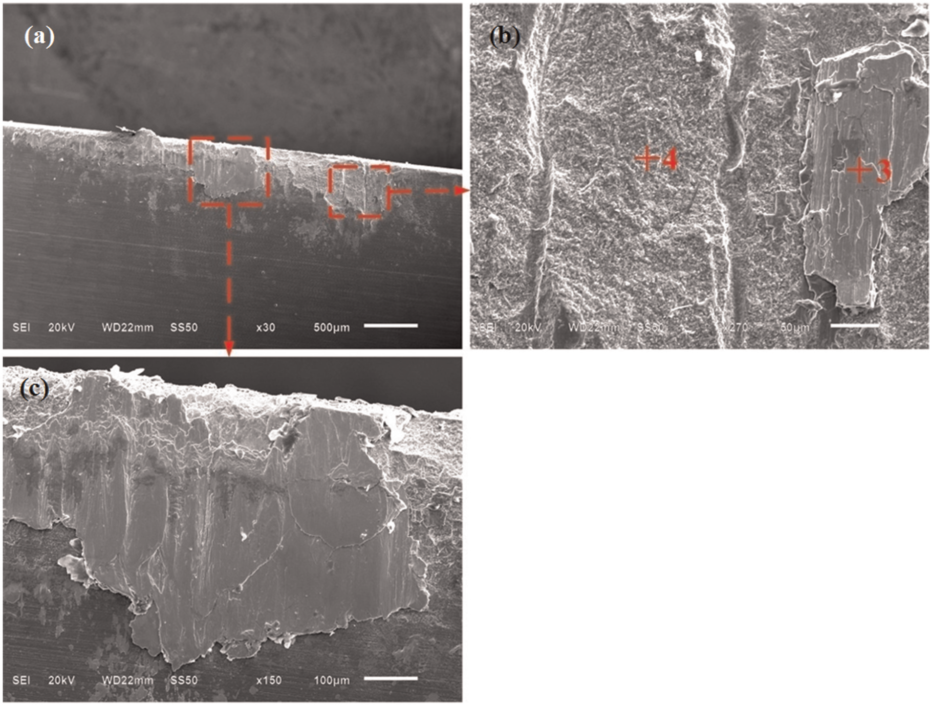
SEM images of flank face of KY1540 at V = 3000 m/min.
More microcracks are found at the cutting speed of 3000 m/min for KY4300, as shown in Figure 13. Except for the transverse microcracks along the cutting edge, many microcracks perpendicular to the cutting edge are observed in the exposed substrate of the worn tool as well, and these are typical thermal cracks. Considering the low thermal conductivity of Inconel 718, the cutting temperature will reach a rather high value at this cutting speed. Milling is an intermittent cutting process, and the tools are subjected to severe alternating thermal and mechanical stress at relatively high cutting speed. Once the stress exceeds the tensile strength of the tool material, microcracks begin to initiate and propagate. The microcracks make the tool easy to fracture under high mechanical and thermal shock and aggravate the notch wear. As for KY1540, adhesion is more serious (see Figure 14(b) and (c)). Although there are many wear traces on the substrate of the tool (Figure 14(b)), no microcracks are found. This is perhaps due to the higher thermal shock resistance and fracture toughness of SiAlON ceramic tools than the whisker-reinforced alumina ceramic tools. 16 EDS analysis of points 3 and 4 in Figure 14(b) is shown in Figure 15. Point 3 is enriched in Cr (15.08 wt%), Fe (8.83 wt%) and Ni (22.56 wt%) coming from the workpiece material, while point 4 is enriched in N (23.72 wt%), O (10.84 wt%), Al (5.13 wt%) and Si (36.24 wt%) coming from the SiAlON ceramic tool material. A significant amount of O (15.98 wt%) element is found on point 3, and it is the evidence of oxidation wear under elevated cutting temperature.
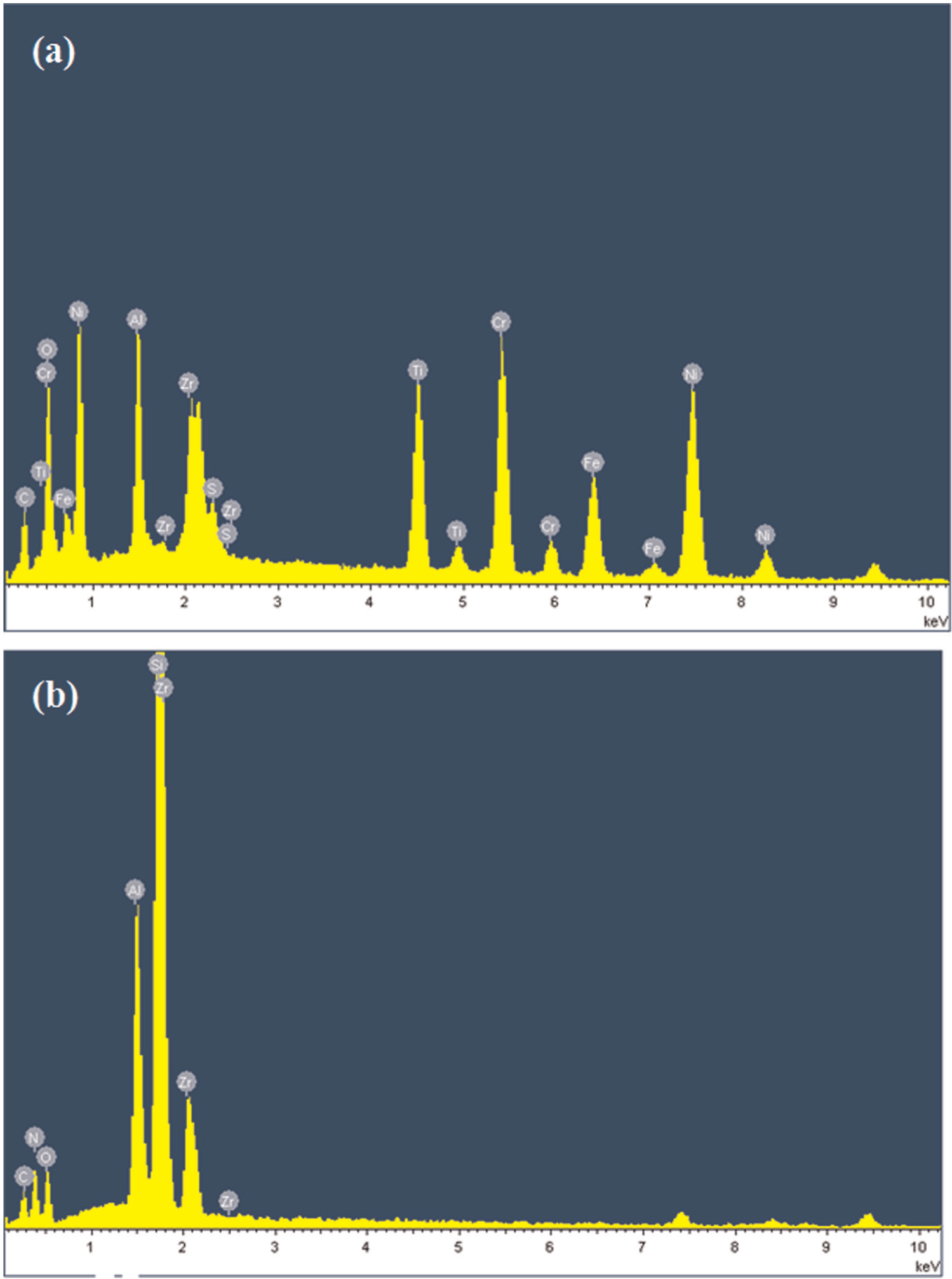
EDS analysis of (a) point 3 and (b) point 4 in Figure 12(b).
Surface roughness
Surface roughness is the most widely used method to quantify the surface integrity of a part. 18 It has significant influence on stress corrosion resistance and creep strength of the machined surface, which in turn affects the service life of components, so it is an important factor in predicting the capability of machining performance. 19 Figure 16 compares surface roughness under different cutting speeds for KY4300 and KY1540 ceramic tools. For comparing, five values were measured at the beginning of the cutting process for each cutting test, and the mean values were obtained. Since the tool life of ceramic tools is limited in high-speed face milling of Inconel 718, intensive tool wear happens immediately after engaging into the workpiece material, so it is necessary to consider the effects of cutting speed and tool wear on the surface roughness together. Obviously, when the cutting speed is less than 1300 m/min for KY4300 and 1800 m/min for KY1540, surface roughness decreases with the cutting speed. When the cutting speeds are relatively low, serious tool wear makes the surface roughness very high. At higher cutting speeds, the softening of the material due to increased cutting temperature results in smaller VC, and it leads to a smoother finish and so lower surface roughness. Turning points appear at the cutting speed of 1500 m/min for KY4300 and 2100 m/min for KY1540; the surface roughness shows a trend to increase slightly. This is due to the rapid drop of the mechanical properties of the tools under high cutting temperature. Perhaps, the higher thermal shock resistance of SiAlON ceramic tools makes the turning point of KY1540 to come later. With further increase in the cutting speeds to 2500 and 3000 m/min, surface roughness decreases again because of the rather small VC as discussed in section “Tool failure patterns.” At the same cutting speed, the surface roughness for KY4300 is smaller than KY1540. This is opposite of VC, as shown in Figure 3. During the cutting process, due to the lower hardness of the SiAlON ceramic tools, adhesion is more serious (see Figures 2 and 3) and leads to a higher surface roughness value.
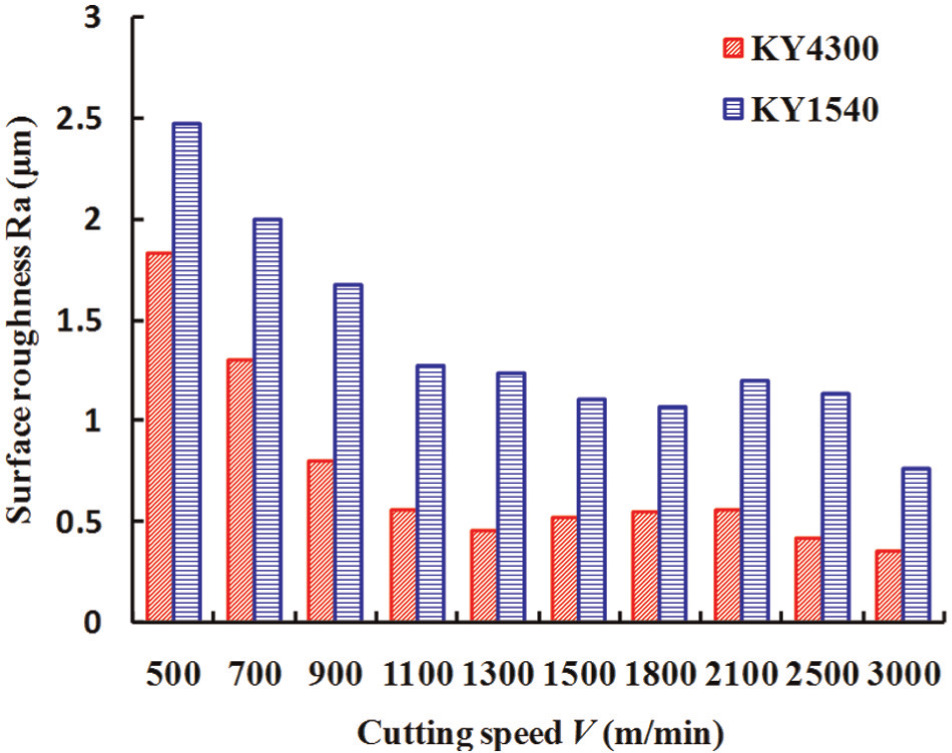
Surface roughness under different cutting speeds.
Conclusion
High-speed face milling tests of nickel-based alloy Inconel 718 were carried out with whisker-reinforced alumina and SiAlON ceramic tools. The cutting forces, tool failure types, failure mechanisms and surface roughness with the two kinds of cutting tools were compared and analyzed, and the following conclusions can be made from the findings of the study:
The resultant cutting forces have a tendency to decrease at first and then increase with the increase in cutting speed for the two kinds of cutting tools. The resultant cutting force of SiAlON ceramic tool KY1540 is much bigger than that of whisker-reinforced alumina ceramic tool KY4300 at the same cutting speed.
The failure types in high-speed face milling of Inconel 718 using ceramic tools were flaking, notching, adhesion, microcracks, chipping and abrasion. Notch wear at the depth of cut VN has a tendency to decrease with the increase in cutting speeds, while nose notch wear VC decreases firstly and then increases. KY1540 shows better performance with respect to notch wear resistance and thermal shock resistance than KY4300.
Better surface integrity can be got using whisker-reinforced alumina ceramic tools KY4300 than SiAlON ceramic tools KY1540 in high-speed face milling of Inconel 718.
Footnotes
Appendix 1
Declaration of conflicting interests
The authors declare that there is no conflict of interest.
Funding
This study is sponsored by the National Basic Research Program of China (2009CB724402), the National Natural Science Foundation of China (51175310), the Scientific Research Foundation for the Excellent Middle-Aged and Youth Scientists of Shandong Province of China (BS2011ZZ010) and the Independent Innovation Foundation of Shandong University.