
Abstract
High-speed milling, which provides an efficient approach for high-quality machining, is widely adopted for machining difficult-to-machine materials such as Inconel 718. For high-speed milling of Inconel 718 curved surface parts, the spindle speed which determines cutting speed directly is regarded as an important cutting parameter related to tool wear and machining efficiency. Meanwhile, because of the changing geometric features of curved surface, cutting force is changing all the time with the variation of geometric features, which influences not only tool wear but also machining quality significantly. In this study, the influence of spindle speed on coated tool wear in high-speed milling of Inconel 718 curved surface parts is studied through a series of experiments on considering tool life, cutting force, cutting force fluctuation, and machining efficiency. According to the experimental results, the appropriate spindle speed that can balance both the tool life and the machining efficiency is selected as 10,000 r/min for high-speed milling of Inconel 718 curved surface parts. In addition, the coated tool wear mechanism is investigated through scanning electron microscopy–energy dispersive x-ray spectroscopy analysis. The results show that at the beginning wear stage and the stable wear stage, the coated tool wear is mainly caused by mechanical wear. Then, with the increasing cutting temperature due to the blunt tool edge, the tool wear becomes compound wear which contains more than one wear form so as to cause a severe tool wear.
Introduction
The excellent mechanical properties for Inconel 718 such as high corrosion resistance, high strength, anti-fatigue, good ductility, and resistance to creep at high temperature make it appropriate for using widely in the field of aerospace.1,2 However, the poor machinability caused by inherent characteristics such as low thermal conductivity and work hardening leads to a severe tool wear.3–6 High-speed machining, which possesses high material removal rate and low cutting force, 7 provides an efficient approach for machining Inconel 718 with high quality and high efficiency. However, because of the work hardening of Inconel 718, the cutting speed is not the higher, the better. As cutting speed is mainly determined by spindle speed, it is of vital importance to select an appropriate spindle speed which can balance both tool life and machining efficiency in high-speed milling of Inconel 718 curved surface parts.
In order to reduce tool wear degree and prolong tool life, a lot of studies have been conducted so as to prolong tool life by selecting different machining conditions. De Oliveira Junior et al. 8 found that using high-pressure cooling was an efficient method for machining low-machinability materials which could extend service life of cutter. Grzesik et al. 9 studied tool life influenced by rake angle and cutting speed of cutters via turning method and found that the friction coefficients changed substantially during tool wear progression. Nouari and Makich 10 focused on the effect of cutting parameters and the mechanisms of chip formation process with tool wear and found that tool wear process was facilitated by the high cutting temperature and the generation of high stresses. Liang et al. 11 investigated the influence of tool wear caused by different coating material by turning titanium alloy, and energy dispersive x-ray spectroscopy (EDS) method was used for tool wear analysis. The research results show that WC-10Ni3Al was suitable for high-speed machining of titanium alloy because of its excellent crater and flank wear resistance. Kaynak et al. 12 investigated factors that affected tool wear in machining process and found that cryogenic machining could improve the performance of cutting tool substantially. Bordin et al. 13 found that the higher the cutting speed and feed rate, the faster the tool wear speed. In addition, the cryogenic cooling could reduce the tool wear efficiently when machining Ti6Al4V. Cantero et al. 14 studied tool wear patterns in turning Inconel 718 and found that side cutting edge angle had great influence on tool wear mode. Tian et al. 15 investigated the effect of milling method on tool wear mechanisms in high-speed milling of Inconel 718 and found that the flaking on rake face and notching on flank face were more serious in down milling than that in up milling. Meanwhile, a group of researchers devoted themselves to predicting tool wear by establishing forecasting models. Chinchanikar and Choudhury 16 developed a model that could predict the flank wear process with machining time by supplying cutting conditions, tool geometry, and material properties. Hao et al. 17 built up a flank wear model about turning Inconel 718 by physical vapor deposition (PVD)-coated carbide tool based on the wear delamination theory, with which the optimum cutting temperature could be calculated and the tool wear reached to the minimum value at the optimum machining temperature. Camargo et al. 18 built up a mathematical model for polycrystalline cubic boron nitride (PCBN) tool wear estimation through a multiple-regression analysis. According to the former investigation, it can be found that cutting parameters optimization on high-speed milling of Inconel 718 curved surface parts whose cutting amount is changing all the time that makes the machining processing quite complex is seldom mentioned.
However, cutting force is one of the most important parameters which reflects the tool wear degree directly. 19 With regard to the Inconel 718 parts with complex curved surface, the geometric features are changing constantly. Because of the variation of geometric features, the cutting force waves sharply so as to bring about vibration of machine tool and shortening tool life of milling cutter which affect the high-speed milling quality significantly. As an important cutting parameter in high-speed milling and in order to improve surface quality and prolong tool life, suitable spindle speed should be selected to guarantee the stability of cutting force and avoid cutting tool from being worn out very quickly for high-speed milling of Inconel 718 curved surface parts.
In this study, the tool wear mechanism of coated ball-end mill was analyzed through scanning electron microscopy–energy dispersive x-ray spectroscopy (SEM-EDS) analysis. Experimental studies were conducted for searching the optimal spindle speed in high-speed milling of Inconel 718 curved surface parts on considering coated tool life, cutting force, cutting force fluctuation, and machining efficiency. This study provides an important guidance for reducing coated tool wear speed and guaranteeing machining efficiency in high-speed milling of Inconel 718 curved surface parts.
Experimental system
The research on tool wear in high-speed milling of Inconel 718 curved surface parts are conducted by setting up a series of experiments. The material and equipments needed in experiments are shown in this section.
Material of the test piece
An Inconel 718 curved surface parts whose generatrix is a sine curve is selected as the test piece, as shown in Figure 1. The equation of the sine curve is

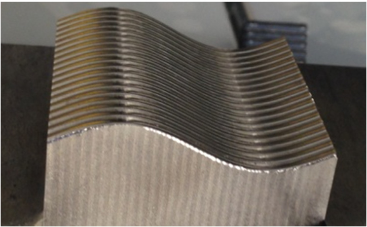
Test piece.
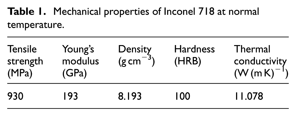
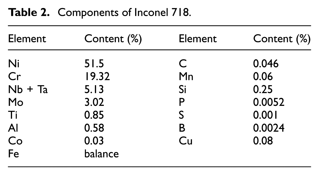
The mechanical properties and nominal composition of the test piece material Inconel 718 are listed in Tables 1 and 2. By utilizing this test piece, tool wear experiments based on high-speed milling are conducted.
Mechanical properties of Inconel 718 at normal temperature.
Components of Inconel 718.
Machine tool
High-speed three-axis vertical milling machine tool MIKEON HSM500 with HEIDENHAIN iTNC530 NC system is adopted to conduct the experiments. The spindle speed can reach up to 54,000 r/min. Its positioning accuracy is 5 µm and the power of the spindle motor is 16 kW.
Cutting tool
Coated solid carbide tools, with the superiority of high tenacity, high hardness, and high wear resistance, are widely used in milling difficult-to-machine materials such as Inconel 718.20,21 In this study, the ball-end milling cutter with two flutes made by NTM Corporation is selected for studying tool wear under high-speed milling condition. The rake angle is 5.5°, the relief angle is 12°, and the helix angle is 30°. The coated material is AlTiN.
Dynamometric device
Cutting force measuring system is composed of KISTLER Multi-component Force Plate Type 9253B23, Multichannel Charge Amplifier Type 5080, and DAQ for DynoWare Type 5697 that are made in Switzerland. The sampling rate of cutting force is 3000 Hz.
Observation device of tool wear
A VHX-600E ultra-depth of field 3D digital microscope system produced by KEYENCE Corporation is used for observing the tool wear. In this system, a 1/1.8 in charge-coupled device (CCD) is adopted, the maximum pixel number is 54 million, and the amplification factor is between 20 and 5000.
Element analysis device
SEM (equipment) and EDS (equipment) that are produced by AMETEK Corporation are used for analyzing the component element of cutting tool after high-speed machining process.
Experimental preparation
Experiment is the main method for conducting this investigation. In this way, some correlated concepts, rules, parameters, and details that are necessary for the experiments need to be put forward at first.
Calculation for effective milling speed
This study is aiming at finding the influence of spindle speed on tool wear in high-speed milling condition for Inconel 718 curved surface parts and finding the appropriate spindle speed for slowing down coated tool wear with high machining efficiency under high-speed milling condition. As the milling speed is determined by both spindle speed and milling radius, the initial premise is to get the effective milling radius Re so as to satisfy the high-speed milling requirement. According to the effective milling radius, effective milling speed ve can be obtained to determine the spindle speed range for experiments. In this study, the machining path is along with the generatrix of curved surface. Because of the geometrical feature of the curved surface, the contact position between the cutting tool and the workpiece is changing all the time, which makes the effective milling radius of the cutting tool to change constantly, as shown in Figure 2. The effective milling radius of cutting tool is the longer one of segment QP and segment WM, as shown in Figure 3. Thus, it is necessary to calculate them respectively.
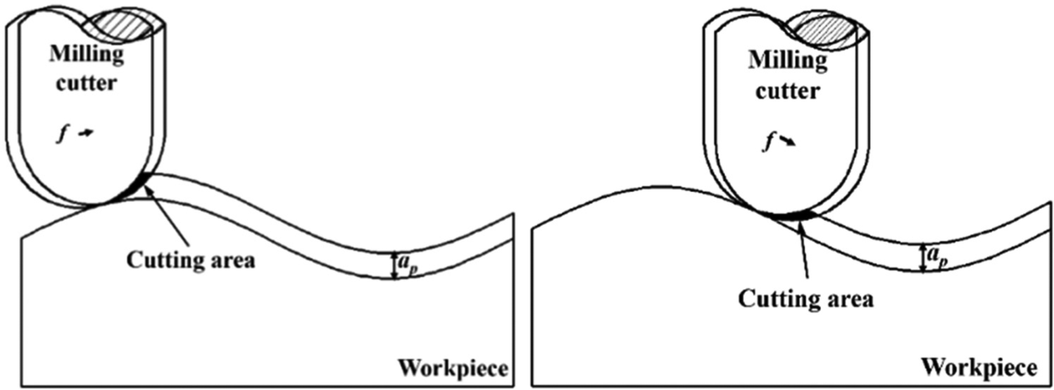
Cutting area for different positions.
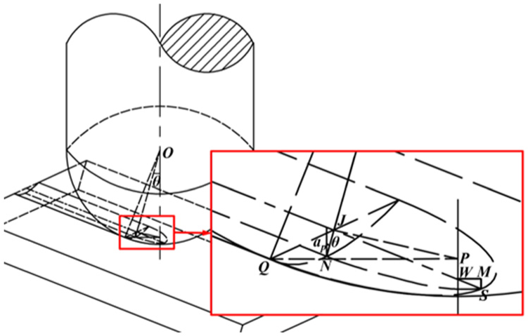
Sketch diagram of machining process.
Calculation for the length of segment QP (lQP)
The equation for the sine curve is

As

where R is cutting tool radius. The effective milling radius Re1 can be calculated as

Calculation for the length of segment WM (lWM)
As shown in Figure 4, the contact point N can be worked out easily, thus the coordinate for point O(xo,yo) can be obtained. Then, the function for the circle and the sine curve can be obtained as

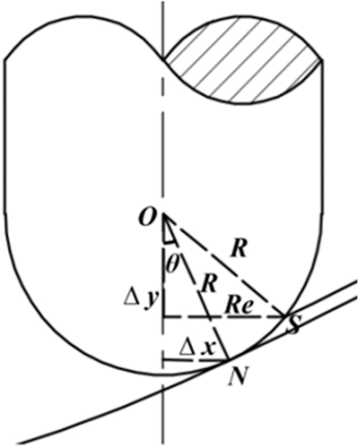
Calculation of effective milling radius.
As a result, the intersection point S(x, y) can be worked out when given (xo, yo). Then, the effective milling radius Re2 can be worked out as

With a comparison between these two values of Re1 and Re2 at the same position, the effective milling radius Re of cutting tool can be obtained as

According to the processing experience, cutting depth ap is selected as 0.3 mm and feed per tooth fz is 0.02 mm z−1 without changing. Spindle speed n is changing from 3000 to 17,000 r/min with the interval of 3500 r/min. Cutting tool radius R equals to 3 mm. The effective milling radius Re for different positions of the sine curve in milling process are shown in Figure 5. The result shows that the smallest effective milling radius is 1.31 mm. As the effective milling speed

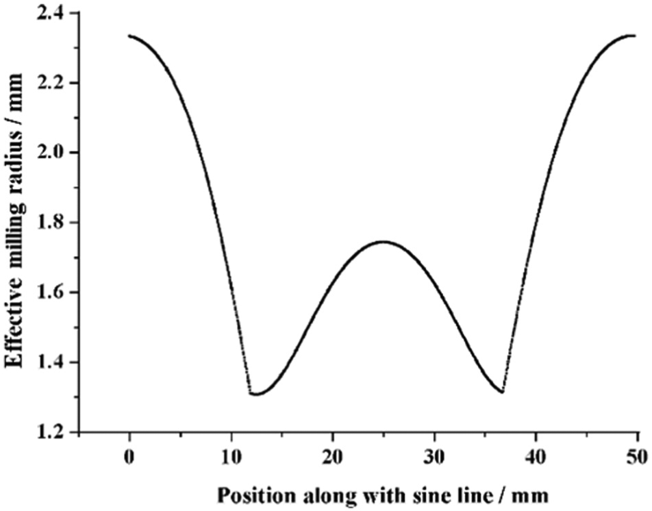
Effective milling radius for different positions of curved line.
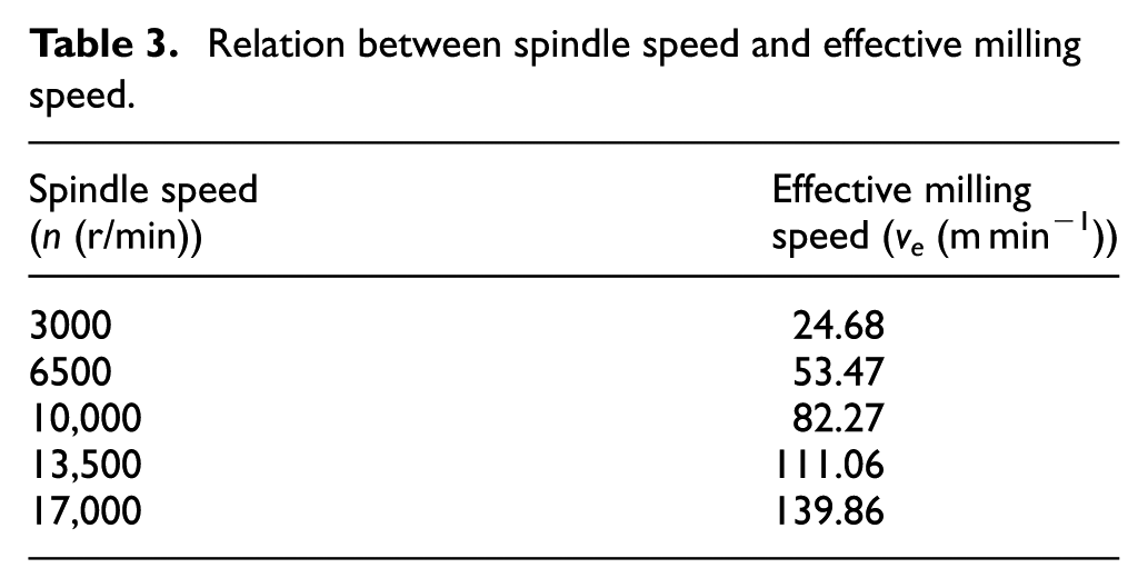
The calculated effective milling speeds for each spindle speed are listed in Table 3. For the high-speed range of machining Inconel 718 is larger than 50 m min−1, 22 the milling process belongs to high-speed machining category when spindle speed is larger than 6500 r/min in this study.
Relation between spindle speed and effective milling speed.
Force data processing method
Tool wear degree can be reflected directly by the change of cutting force in milling process; hence, it is necessary to obtain cutting force value for further spindle speed selection analysis. As noises must be existed in the measured cutting force signals among practical machining process, low pass filter (LPF) method based on the fast Fourier transform (FFT) is adopted for getting rid of noise wave before calculation, then the practical cutting force can be obtained. Fourier transform for cutting force signal is shown in Figure 6. The frequency for each cutter tooth is twice as the spindle rotation frequency. As a result, the cutter tooth frequency (TPF) = 2SF. By observing each cutting force signal, it can be obtained that all the frequencies are below 6SF. Thus, 6SF is selected as the demarcation point for LPF.
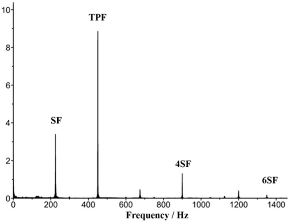
Fourier transform for cutting force signal(n = 6000 r/min).
After receiving actual cutting force signal, the approach for obtaining cutting force values at sampling points needs to be studied. Seven points with different geometric features (including slope and curvature) which divide the whole sine curve into eight equal segments are selected as the sampling points, as shown in Figure 7. Point B is the convex point, point F is the concave point, and point D is the inflection point. These three points are the feature points on the sine curve. Points A, C, E, and F are the general points on the sine curve. In this way, the selected seven points are represented. The cutting forces for the seven points can be used for the following study of influence of spindle speed on tool wear in high-speed milling of Inconel 718 curved surface parts. In order to get cutting forces for each points, the cutting time should be calculated based on the machining numerical control (NC) code. As shown in Figure 8, taking point D as an example, the slope can be obtained by utilizing equation (2) when x equals to 25 mm, just

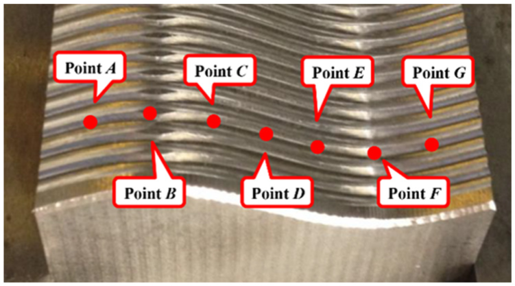
Sampling points of cutting force.
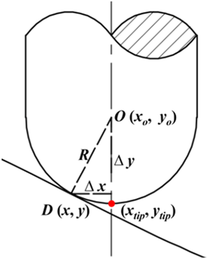
Calculation for cutting tool tip-coordinate of force measuring point.
As a result, θ equals to 26.69°. In this way

Thus, the x-coordinate for cutting tool tip xtip can be expressed as

This x-coordinate can be found among NC code for machining the sine line. Then, the total cutting time from the starting point to point D can be calculated, and the cutting force can be obtained from the measured cutting force signal according to the cutting time. At last, the cutting moment can be found among the de-noised force measuring data, as shown in Figure 9. Three peak values of cutting force are selected on both sides of the calculated time of sampling point, respectively. The average cutting force value of these six points is taken as the cutting force component. Then, the resultant force can be obtained by
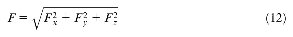
where Fx, Fy, and Fz are the three cutting force components. Cutting forces for the other six points can also be obtained by the same method.
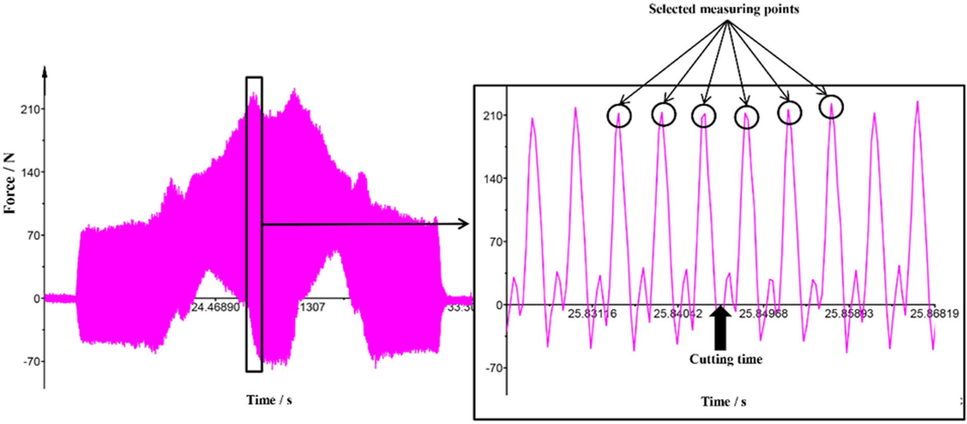
Cutting force signal (n = 6000 r/min).
Experimental detail and evaluation rule
In order to study the influence of spindle speed on tool wear, evaluation rule for tool wear degree and experimental detail for measuring strategy are given for better understanding of this study.
Tool wear zone width
In this study, the tool wear degree is evaluated by tool wear zone width (TWZW) which is defined as the maximum distance of the tool wear zone, as shown in Figure 10.
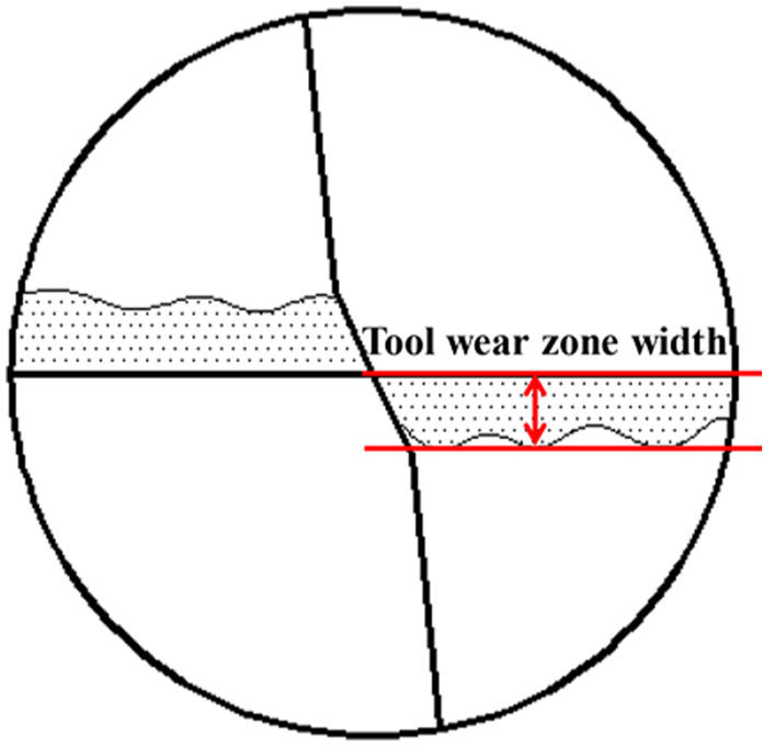
Tool wear zone width.
Measuring principle
In this study, equal cutting distance principle is used to investigate the influence of spindle speed on tool wear in high-speed milling of Inconel 718 curved surface parts. Based on this principle, two steps are divided for measuring tool wear degree. At step 1, namely at the beginning of the experiment, every five sine lines cutting is defined as one cutting segment. Step 1 contains five cutting segments and then goes to step 2 which is a relatively stable tool wear period. For step 2, 20 sine lines cutting is defined as one cutting segment. TWZW is measured after finishing each cutting segment. The cutting force value is measured at the middle of each cutting segment.
Failure criteria
TWZW = 0.2 mm is selected as the failure criteria, which means that when TWZW reaches up to 0.2 mm, the cutting tool cannot be used any longer and the test will be stopped.
Results and discussion
As mentioned above, the experiments are conducted and the influence of spindle speed on tool wear is investigated based on tool wear, cutting force, cutting force fluctuation, and machining efficiency. Then, the characteristics and mechanisms of coated tool wear are analyzed according to the experimental results.
Influence of spindle speed on coated tool wear
As an important machining parameter, spindle speed has great influence on coated tool wear in high-speed milling of Inconel 718 curved surface parts. When spindle speed is too high, the cutting temperature is high. Because of the geometrical feature of curved surface, cutting fluid cannot reach the cutting position all the time which makes the flaking phenomenon emerge due to the sharp change of temperature. In order to guarantee a normal cutting process and realize high-quality and high-efficiency processing, the influence of spindle speed on coated tool wear in high-speed milling of Inconel 718 curved surface parts is studied by considering tool life, cutting force, cutting force fluctuation, and machining efficiency so as to select appropriate spindle speed.
Influence of spindle speed on coated tool wear by analyzing tool life
The rake face wear and flank face wear for high-speed milling of Inconel 718 curved surface parts with different spindle speeds are shown in Figure 11 based on the measuring principle of TWZW in section “Experimental detail and evaluation rule.” It can be found that the coated tool has a severe wear stage at the beginning period, and then it steps into a stable wear stage which lasts for a quite long time, and at last, it experiences a rapid wear stage before scraped. The overall tendency of coated tool wear is increasing when the spindle speed increases. While for spindle speed that is higher than 13,500 r/min, the coated tool wear is exceptionally severe because of the high cutting temperature which leads to a severe work hardening of Inconel 718 and the softening of cutting tool. Hence, the spindle speed that is lower than 13,500 r/min can be selected to slow down the coated tool wear speed on considering tool life.
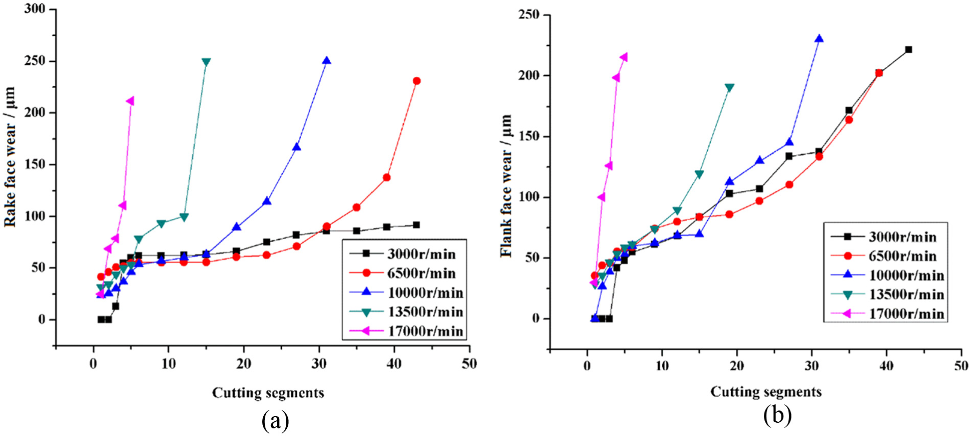
Coated tool wear along with different spindle speeds: (a) rake face wear and (b) flank face wear.
Influence of spindle speed on coated tool wear by analyzing cutting force
For cutting force, which can truly manifest the tool wear degree, it is undoubted that the smaller the cutting force, the slower the tool wear. Point D shown in Figure 7 is chosen as an example for cutting force analysis, and cutting force variation tendency for the seven sampling points are the same. Based on the measuring principle of cutting force in section “Experimental detail and evaluation rule” and the force data processing method in section “Force data processing method,” cutting force variation for point D with different spindle speeds is shown in Figure 12. It can be seen that with the increasing spindle speed, the cutting force first decreases and then increases. The smallest cutting force emerges at the spindle speed of 10,000 r/min. The reason is that when the spindle speed increases, the shear angle becomes larger which leads to a smaller cutting force. However, the high cutting temperature caused by high milling speed results in not only work hardening of workpiece but also hardness decreasing of coated tool so as to make the cutting force get larger and lead to a severe coated tool wear problem. According to the experimental results, it can be concluded that neither too low spindle speed nor too high spindle speed is appropriate, the most suitable spindle speed in this study is 10,000 r/min on considering cutting force.
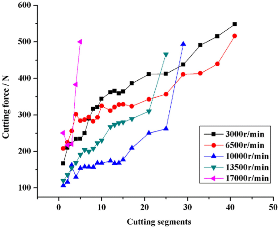
Cutting force variation for different spindle speeds.
Influence of spindle speed on coated tool wear by analyzing cutting force fluctuation
The machining path is along with the generatrix of curved surface. Due to the change of geometric features for curved surface, the chip volume will vary in high-speed milling process. In this way, cutting force is changing constantly which leads to vibration of machine tool and wear of milling cutter so as to affect machining quality and tool life severely.
In this study, the difference value between the cutting force at point D, which is the maximum cutting force, and the cutting force at point A, which is the minimum cutting force, is defined as cutting force fluctuation. The larger the cutting force fluctuation, the faster the tool wear. Thus, choosing an appropriate spindle speed which can effectively reduce cutting force fluctuation is of vital importance. The results of cutting force fluctuation for different spindle speeds are shown in Figure 13. It can be seen that when spindle speed is 10,000 r/min, the cutting force fluctuation is the smallest. Consequently, 10,000 r/min is an appropriate spindle speed for high-speed milling of Inconel 718 curved surface parts on considering the cutting force fluctuation.
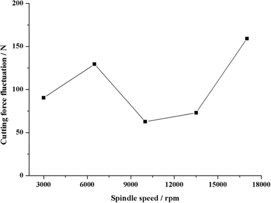
Cutting force fluctuation for different spindle speeds.
Influence of spindle speed on coated tool wear by analyzing machining efficiency
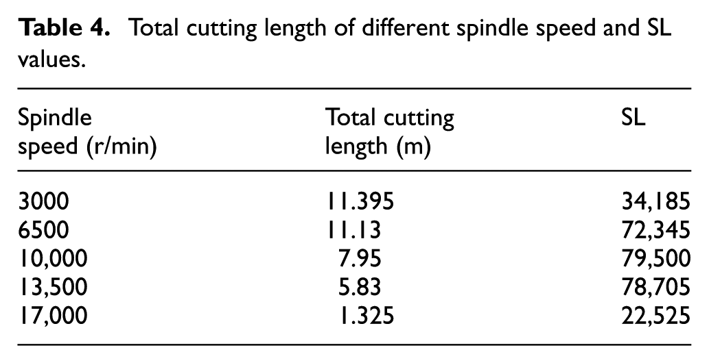
As the tool wear is influenced a lot by spindle speed, an appropriate spindle speed needs to be obtained for guaranteeing not only tool lifespan but also machining efficiency. To satisfy this requirement, a parameter SL is defined as follows: SL = (spindle speed) × (cutting length). According to equation (1), the cutting length for one sine line can be calculated as 53 mm, thus the total cutting length from the beginning of tool wear process to the cutting tool scrap are shown in Table 4. Moreover, the calculated SL values are also shown in Table 4. The higher the SL value, the better the spindle speed. It can be seen that SL value for the spindle speed of 10,000 r/min is the largest, which also proves that 10,000 r/min is the most suitable spindle speed for machining.
Total cutting length of different spindle speed and SL values.
Synthetically considering tool life, cutting force, cutting force fluctuation, and machining efficiency, the appropriate spindle speed is 10,000 r/min.
Analysis for characteristics of coated tool wear
On the basis of experimental results, the coated tool wear can be divided into three stages. At the first stage, the coated tool wear is fast because of the tiny contact area between cutting tool and workpiece among the very beginning cutting process and this stage will last for a very short time. At the second stage, the coated tool wear is mainly occurred at the coated layer. Because of the wear-resistance property of the coated material, the coated tool wear is quite slow at this time which makes it last for a long time until the coated layer is worn off. At the third stage, the wear process steps into a rapid wear stage because of the direct contact between workpiece and base material of cutting tool. Consequently, the cutting tool runs out very quickly without the protection of coated layer.
Furthermore, the flank face wear variation tendency is different from that of the rake face wear along with the changing of spindle speed. It can be obtained through Figure 14 that when spindle speed is 10,000 r/min, the flank face wear is 66.75 µm after five cutting segments, which is not changing much compared with the 68.73 µm for the low spindle speed of 3000 r/min. However, the rake face wear is 62.88 µm which becomes more severe than 31.06 µm for the low spindle speed. Compared with flank face wear, the rake face wear is affected more by spindle speed. Hence, the rake face wear is more sensitive to spindle speed than flank face wear.
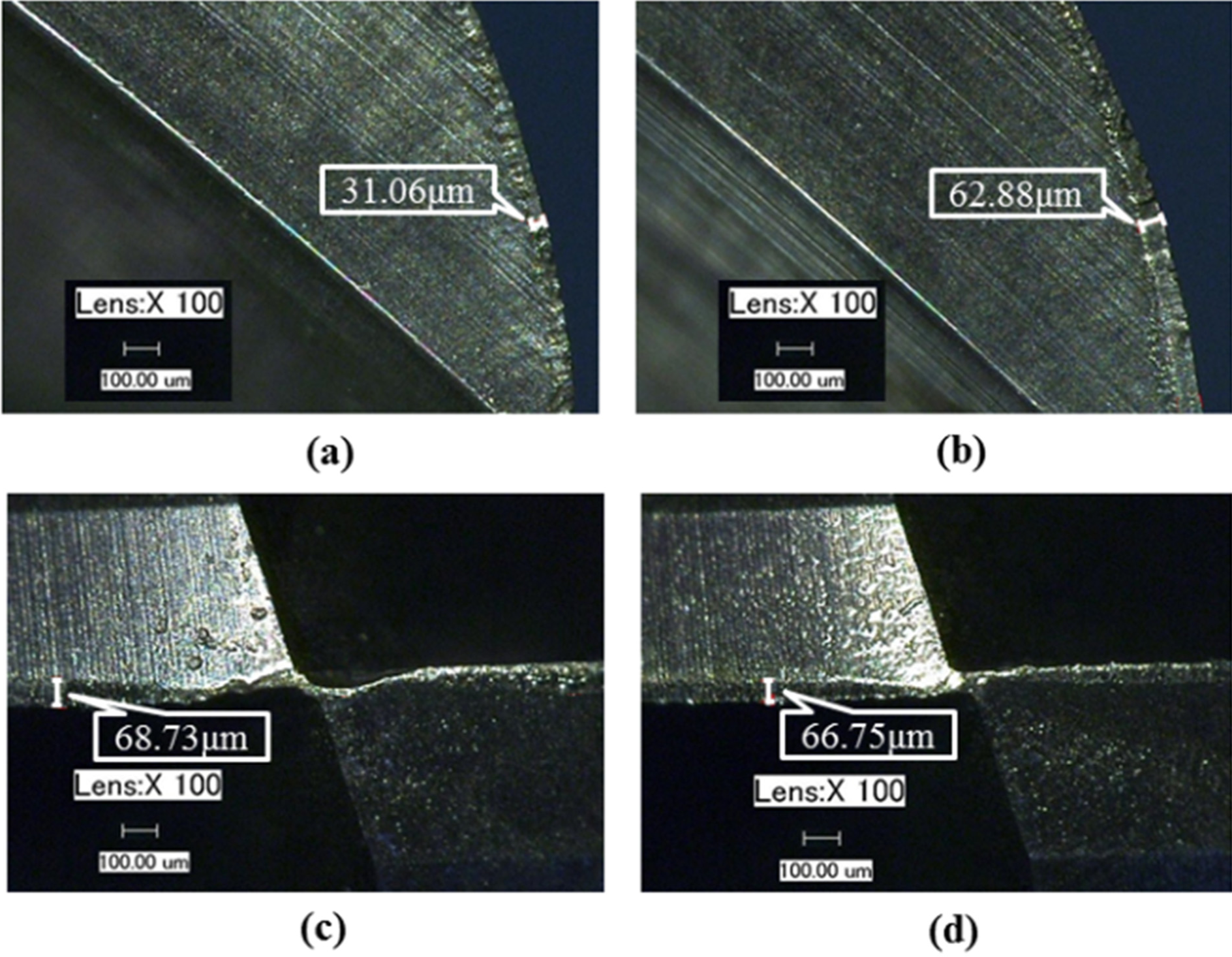
Tool wear comparison between different spindle speeds: (a) rake face wear (n = 3000 r/min), (b) rake face wear (n = 10,000 r/min), (c) flank face wear (n = 3000 r/min), and (d) flank face wear (n = 10,000 r/min).
Analysis for coated tool wear mechanism
According to experimental results, the tool wear mechanisms are the same for different spindle speeds. It can be found that at stage 1 which contains the beginning wear stage and the stable wear stage, the cutting tool is sharp that leads to small cutting force. The main coated tool wear mechanism for stage 1 is mechanical wear which is caused by the friction of cutting tool and workpiece. At this time, the rake face has scored a lot of grooves because of the impurity in workpiece material. It is called the hard spots wear which is the initial coated tool wear form for high-speed milling of Inconel 718 curved surface parts.
Then it steps to stage 2 that refers to the rapid wear stage, the coated tool becomes blunt and the coated layer becomes broken which results in severe friction and causes large cutting force and cutting temperature. Consequently, the mechanism of coated tool wear becomes quite complex. SEM-EDS analysis is adopted for obtaining the elementary composition so as to further investigate the mechanism of coated tool wear. The results are shown in Figure 15, from which it can be seen that spot 1 is composed of Ni element, which indicates that the workpiece material is bonding to coated tool and adhesive wear occurs. For spot 2, the appearance of oxygen element indicates that oxidative wear is happened. Hence, it is a compound wear process which contains more than one wear mechanism. At this condition, the coated tool wear speed becomes so fast that makes cutting tool lose its machining ability very quickly.
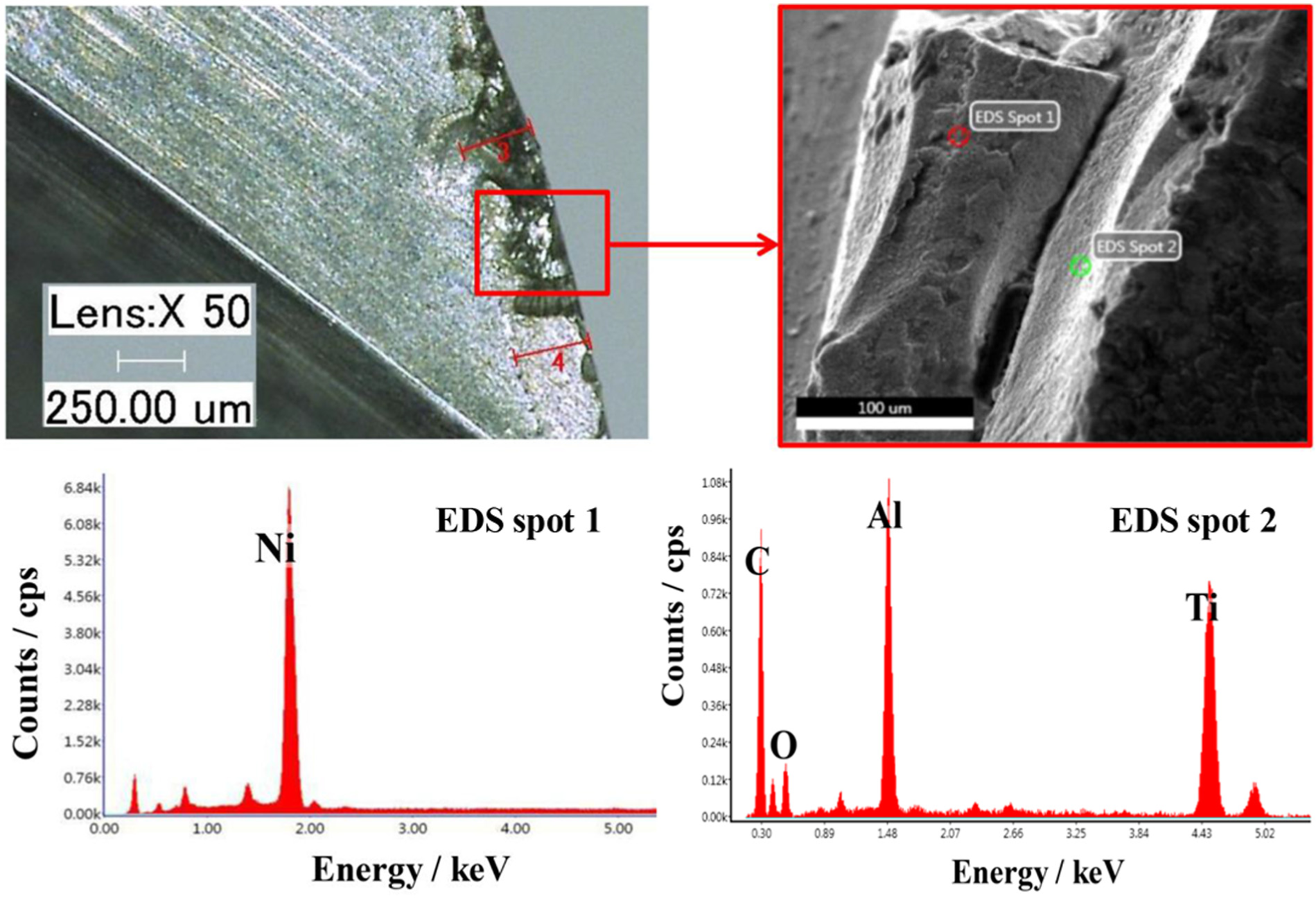
Compound wear (n = 17,000 r/min).
Conclusion
In this study, the influence of spindle speed on tool wear in high-speed milling of Inconel 718 curved surface parts is investigated based on tool life, cutting force, cutting force fluctuation, and machining efficiency. Meanwhile, the coated tool wear characteristics and mechanisms are also analyzed. The results show that
Because of the geometry features of curved surface, the chip volume for different positions is changing a lot, which leads to sharp fluctuation of cutting force and results in severe cutting vibration in high-speed milling. Thus, the cutting tool will be worn more serious for machining curved surface parts than flat surface parts.
The overall tendency of the coated tool wear is increasing when the spindle speed increases. When the spindle speed is too high, due to the poor thermal conductivity, work hardening influences more about cutting force than that of the shear angle increasing which makes the cutting force to decrease at first and then to increase when the spindle speed is increasing. Consequently, appropriate spindle speed is of vital importance for slowing down tool wear.
The coated tool wear mechanisms for different tool wear stages are not the same. At first, the coated tool wear mechanism is hard spots wear. Then, due to high cutting temperature caused by high spindle speed as well as the blunt cutting edge, the coated tool wear form becomes compound wear that makes coated tool to run out very quickly.
Both the cutting force and the cutting force fluctuation are relatively small when the spindle speed is 10,000 r/min. Based on this spindle speed, machining efficiency and tool life can also be guaranteed for high-speed milling of Inconel 718 curved surface parts.
The results of this study provide a theoretical basis for coated tool wear mechanism and spindle speed selection in high-speed milling of Inconel 718 curved surface parts and supply a reference cutting parameter value for machining Inconel 718 parts. Further research will be conducted by investigating coated tool wear law affected by different geometrical parameters of cutting tools in high-speed milling of Inconel 718 curved surface parts.
Footnotes
Acknowledgements
The authors wish to thank the anonymous reviewers for their comments which led to improvements of this paper.
Declaration of conflicting interests
The author(s) declared no potential conflicts of interest with respect to the research, authorship, and/or publication of this article.
Funding
The author(s) disclosed receipt of the following financial support for the research, authorship, and/or publication of this article: The project is supported by the National Natural Science Foundation of China (no. 51575087), Science Fund for Creative Research Groups (no. 51321004), Basic Research Foundation of Key Laboratory of Liaoning Educational Committee (no. LZ2014003), and the Fundamental Research Funds for the Central Universities.