
Abstract
This article describes the results of the experimental research on the heat-affected zone of the subsurface layers of eroded surface on medium-alloyed samples of steel EN X37CrMoV5-1 (W.-Nr. 1.2343) which occurs in die-sinking electrical discharge machining with Cu electrode. It assesses the direct effect and consequences of the heat-affected zone on the final quality of the machined surface. The aim of the experiments was to contribute to the knowledge database defining the influence of the main technological parameters of electrical discharge machining on the microhardness changes and the total depth of the heat-affected zone of the subsurface layers of experimental samples. The results of the experimental measurement were transformed into the mathematical models allowing simulation and prediction of the final quality of the machined surface after die-sinking electrical discharge machining tool steels with Cu electrode. The purpose of the mathematical models is to determine the optimal combination of process parameters and thereby achieve the desired quality of the products produced by this advanced technology.
Keywords
Introduction
Electrical discharge machining (EDM) is characterized by thermal processes in the subsurface layers of material. Therefore, it can be expected that some microstructural changes are directly beneath the machined surface. It was also pointed out by Cusanelli et al., 1 Huang et al., 2 and Mičietová et al. 3 who put an emphasis on the importance of qualitative parameter such as total depth of the heat-affected zone (HAZ). Due to the HAZ, which is characterized by not only the change in the microstructure but also the microhardness changes, can be in general expected to impact the durability and longevity of the products produced by this advanced technology. These assumptions are confirmed by many researchers such as Čada and Zlámalík, 4 Kiyak and Cakir, 5 Orečný etal., 6 Švecová and Madaj, 7 and Valentinčič et al. 8 In their articles, it is reported that especially in this direction are prone the products of tool steels, including medium-alloyed steel with designation EN X37CrMoV5-1 (W.-Nr. 1.2343), because these steels always maintain the same amount of residual austenite which contributes to the formation of so-called white layer (WL). The occurrence of the WL in the tool steel grade, according to the authors Ekmekci, 9 Marafona, 10 and Puri and Bhattacharyya, 11 shows the microstructure of the secondary hardening as a result of intense surface heating during the EDM process. Moreover, the rapid cooling with dielectric fluid in the combination with extreme settings of technological parameters (TP) of electroerosion process can even eventuate in the formation of microcracks on eroding surface. It is confirmed by authors Govindan and Joshi 12 and Liu and Guo. 13 However, the authors Dewangan et al. 14 and Sidhom 15 show some positive aspects of the WL. It follows that with suitable regulation of thermal effect range of the subsurface layers during the electroerosion process, the machined surfaces can be produced with specific properties of predefined quality.
The aim of the experimental research was to contribute to the existing knowledge database through the formulation of various laws in relation to the processes which run directly under the eroded surface of medium-alloyed tool steel EN X37CrMoV5-1 (W.-Nr. 1.2343) using the mathematical modelling and prediction of the HAZ.
Materials and methods
Description of eroded surface in terms of HAZ
The quality assessment of machined surface after die-sinking EDM is a quite complicated process due to many reasons. The quality of machined surface cannot be globally assessed on the base of only one quality parameter.16–18 In practice, the quality of machined surface is often assessed solely on the basis of the roughness parameters (Ra, Rz, and Rq). 19 However, these qualitative indicators in themselves are unable to include the important parameters relating to changes in the microstructure. The microstructure changes occur due to thermal effects of electric discharge with high intensity and subsequent rapid cooling by action of dielectric fluid.20,21 It is demonstrated that the final microstructure and its properties have a substantial impact on operating properties of the product,22,23 and in some cases, these are much more important than surface roughness. Because that the microstructure changes have an impact on changes of mechanical properties of material,24,25 the differences can be assumed in total HAZ depth. Among the basic TP at die-sinking EDM, which substantially affect the final quality of the machined surface in terms of these quality parameters, are the peak current I (A), pulse duration ton (µs), the associated pause for the renewal of the discharge channel called the pulse off-time toff (µs), and the voltage of discharge U (V). The influence of the primary TP of electroerosion process on the machined surface quality of tool steel after die-sinking EDM with Cu electrode with the area of 10 mm2, in terms of the total HAZ depth including their setting range used in experimental making of samples, is shown in Table 1.
Setting range of the main TP in die-sinking EDM of tool steel EN X37CrMoV5-1 with Cu electrode and its influence on the total depth of HAZ.
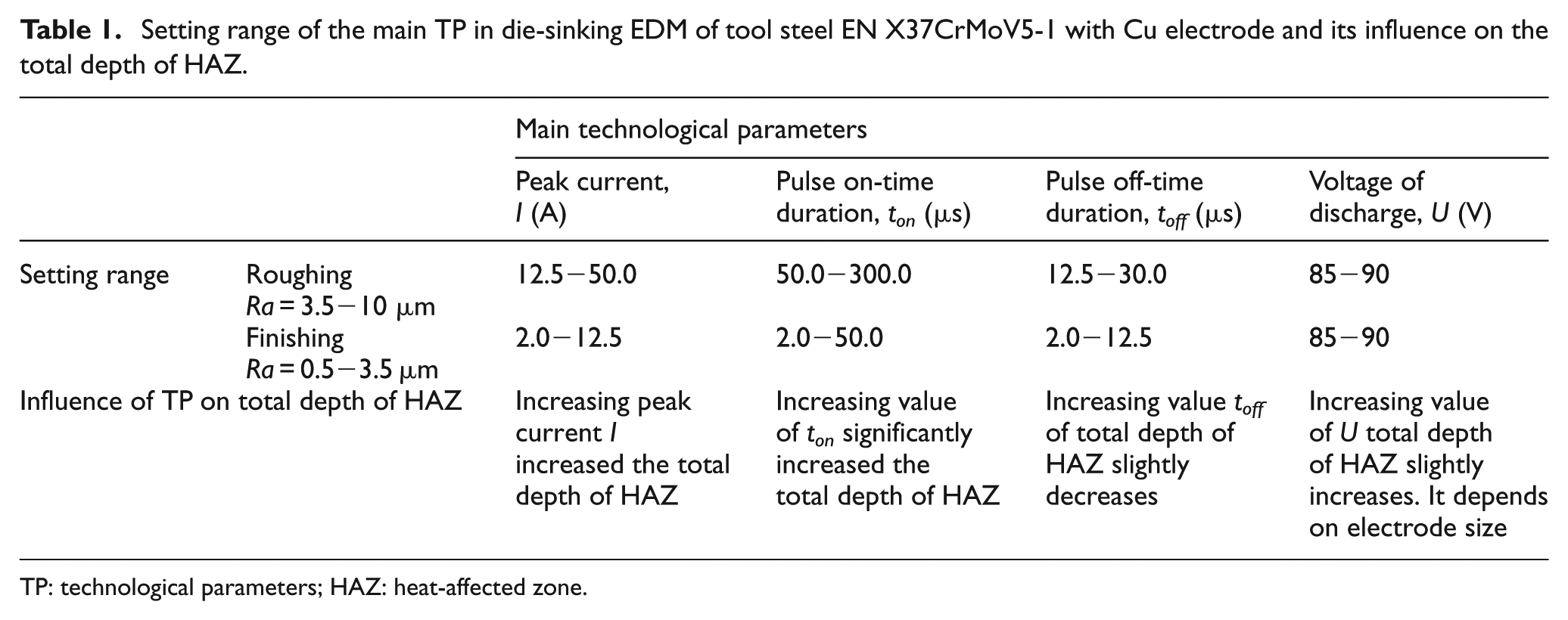
TP: technological parameters; HAZ: heat-affected zone.
Description of samples and devices used in the experiment
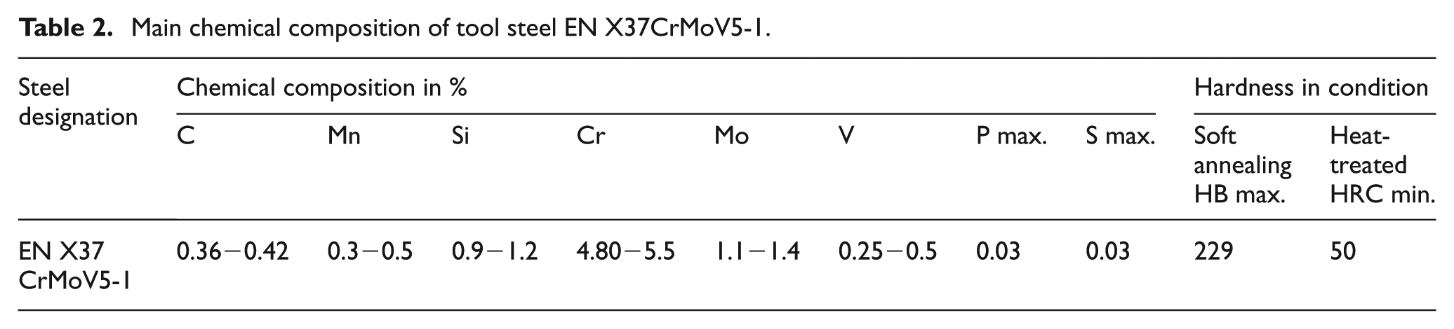
In the experiment, the samples made from steel blocks with dimensions 25 × 55 × 60 mm 3 were used. The used material was the medium-alloyed tool steel EN X37CrMoV5-1 (W.-Nr. 1.2343, STN 19 552) with the strength of Rm = 1600 MPa and with the hardness of basic material (BM) after heat treatment about 54 HRC. It is the medium-alloyed, chromium–molybdenum–silicon–vanadium tool steel, containing alloying elements 0.36%−0.42% of C and 4.8%−5.5% of Cr, which is mostly in practice used for the manufacture of tool for hot moulding, cutting, die casting, and its components. It is characterized by very good full hardness, toughness, high temperature strength, and good plastic properties in normal and elevated temperatures. Similarly, it shows very good resistance to the formation of microcracks due to thermal fatigue and also low sensitivity to the rapid changes in temperature. Table 2 presents the main chemical composition of tool steel EN X37CrMoV5-1 used in the experiment.
Main chemical composition of tool steel EN X37CrMoV5-1.
Experimental samples were made on computer numerical control (CNC) die-sinker EDM machine AGIE FORM 30 (Agie Charmilles SA, Switzerland), which is shown in Figure 1. Used machining tool was Cu electrode with dimensions 10 × 10 mm2. The process fluid was deionized water.
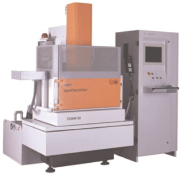
CNC die-sinker EDM machine AGIE FORM 30.
Figure 2 shows the eroded surface of experimental sample of tool steel and the Cu tool electrode.
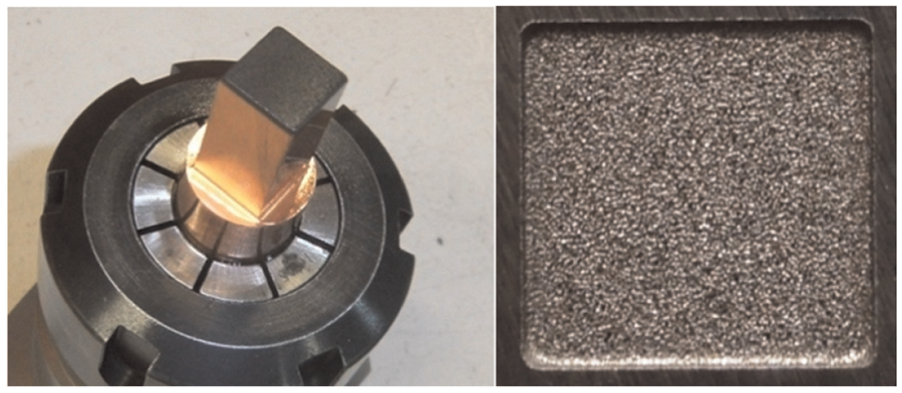
Used Cu tool electrode (left) and eroded surface of tool steel EN X37CrMoV5-1 sample (right).
Sample material of tool steel EN X37CrMoV5-1 (Böhler Edelstahl GmbH & Co KG, Austria) was heat-treated to the hardness about 54 HRC before the erosion. 26 It was heat-treated by hardening in air at temperature about 1030 °C with subsequent tempering at the temperature about 580 °C to the hardness of 53 HRC (Figure 3).
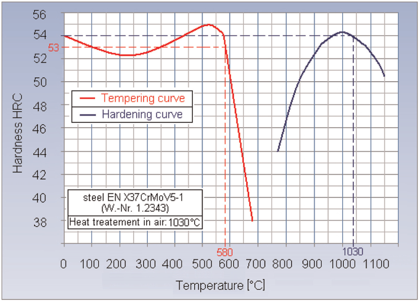
Hardening and tempering diagram of steel EN X37CrMoV5-1. 27
Samples were prepared by pickling in chemical solution Armohib 28 (Akzo Nobel Surface Chemistry AB, Sweden) on the base of H3PO4 with concentration of 15% at constant temperature 40 °C with a total duration of action for 10 min. The advantage of using the stain on the base of H3PO4 is the creation of a thin phosphate film which in consequence protects the surface against its re-oxidation with atmospheric oxygen O2 and H2O humidity.
Microhardness and the total depth of HAZ measurement
Based on observations, the eroded surface of the samples of the steel EN X37CrMoV5-1 using a digital microscope Keyence VHX-5000 (Keyence International, Belgium) clearly shows the changes in the microstructure of the surface layers of the BM, whereby the surface integrity was preserved. On the surface, there were no significant microcracks or other discontinuities which can be attributed to the adequate combination of TP in conjunction with a suitable heat pre-treatment of samples, favourable thermal conductivity of 25 Wm−1 K−1 and electrical conductivity of 1.92 Siemens.m.mm−2 of used tool steel. Figure 4 presents an image of the eroded surface layer of one of the made experimental samples, recorded with digital microscope Keyence VHX-5000 on which the small particles of Cu out-melted of tool electrode is clearly observable.
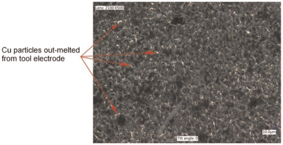
Cu particles observed on eroded surface sample of tool steel EN X37CrMoV5-1 (500× magnification).
Figure 5 shows the individual subsurface layer recorded with the electron microscope JEOL JSM-5900LV (JEOL Ltd, Japan) with 1000× magnification of tool steel after die-sinking EDM with Cu electrode. The settings of the main technological and process parameters were responsible for roughing conditions.
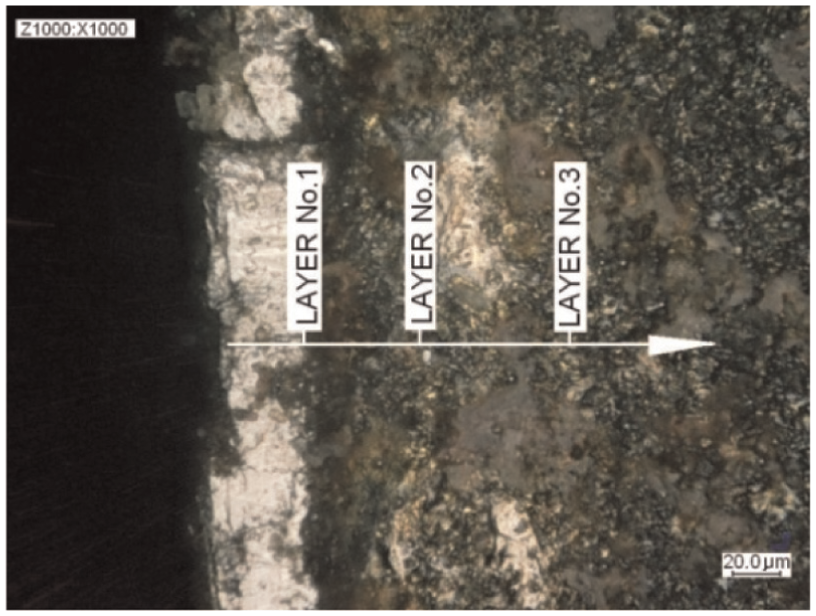
Microstructural changes subsurface layers of tool steel EN X37CrMoV5-1 after die-sinking EDM with Cu electrode in conditions of roughing observed on metallographic images recorded on electron microscope (1000× magnification).
Directly on the eroded surface is situated so-called black layer (BL) which is characterized by black burn composed of metal residues of Cu tool electrode. Under this layer is heat-affected layer which is characterized by the crystallographic microstructure different from the BM. In the most of the eroded surfaces, the dendritic structure can be observed which is the reflection of the crystallization process due to cooling. The presence of this microstructure suggests the low cooling intensity, and it has a direct relation to surface and internal defect formation of eroded surfaces especially in roughing operations. Conversely, in the fine finishing operations where the cooling intensity is relatively high, these microstructures are not observed. The HAZ after die-sinking EDM consists of a layer no.1 called WL and area no.2 called transition layer (TL) which mainly represents tempered martensite. The presence of these microstructures shows on the biphasic solidification development the molten material during cooling by dielectric fluid. In the first phase, it occurs to the thermal convection on the material surface which is in direct contact with the dielectric fluid, whereas in the second phase below the layer, it contributes to the heat removal from the place of electroerosion by convection and conduction. Despite these layers do not have a homogeneous microstructure, the thickness of the WL of the entire cross section of the eroded surface is approximately constant. The thickness of the transitional area in the cross section of the eroded surface is partly different. This deviation depends on the method of EDM, that is, whether it is a roughing, or finishing, and on the cooling intensity. Depending on the above, the estimated thickness of WL in die-sinking EDM of tool steel EN X37CrMoV5-1 is between 10 and 30 µm, and the thickness of TL is between 80 and 200 µm. Area no.3 represents the BM which was not affected by heat input and no microstructural changes due to EDM process. The values of the total depth HAZ and development of the microhardness in the heat-affected layer were determined from experimental measurements. In assessing the total depth of HAZ, it was very important to respect the possible dispersion of the values with respect to the microstructural construction of used material. Building on the studies of several authors was the assumption that the development of microhardness does not need to be the same across the eroded surface, and it was therefore chosen the procedure for implementing measurements in different parts of the eroded surface. 28 Due to the expected very small total depth of the HAZ, which is the order of tens of µm, was created the certain problem in the methodology of measuring microhardness. Because the eroded surface has very small dimensions of 10 × 10 mm2, it was not possible to use the bevelled cross-sectional method. As suitable seemed to be a method of gradual removal of fine surface segments of material. On one hand, this way respects the specifics of EDM advanced technology and additionally solves the problem of small eroded areas.
For the exact assessment of subsurface layer, microhardness of experimental samples was sequentially carried out to the metallographic sections using an automatic grinding (polishing) machine MoPao1000 (Jinan Hensgrand Instrument, China). In the first phase, four metallographic sections were gradually carried out, each with a thickness of 5 µm due to a detailed capture of microhardness course in WL area. In the second phase, the metallographic sections were sequentially carried out, each with the thickness of 10 µm for as long as the measured value of microhardness HV2 was not identical with hardness of BM. The measured value of microhardness was recorded in the table after each metallographic section.
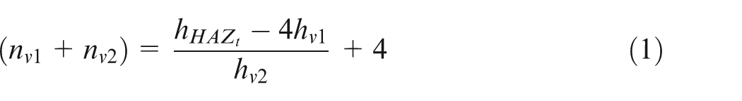
The total number of specimens of the first and the second phases (nv1 + nv2) at the expected (theoretical) total depth of HAZ
where
When the estimated total (theoretical) depth of HAZ was up to 70 µm of the tested experimental samples of steel EN X37CrMoV5-1, manufactured by die-sinking EDM technology of fine finishing, the minimum number of all metallographic sections
The BM hardness of assessed experimental samples ranged 52−53 HRC; therefore, it was not possible to use in the measurement of the Vickers microhardness test STN EN ISO 6507. 29 The load during this test was in the range of 0.098–0.98 N, which is insufficient for a given BM hardness of 52−53 HRC. With this load can be measured the microhardness at maximum limit of 464 HV0.1 which corresponds with Rockwell hardness about 46 HRC. Therefore, Vickers hardness test was used at low-load HV2 according to the ISO standard. It is responsible to the load of tetrahedral pyramid 19.61 N. The hardness measurement in the HAZ on metallographic section of experimental samples with the total eroded surface of 10 × 10 mm2 was realized using a device Zwick ZHV30 Vickers Hardness Tester (Zwick GmbH & Co, Germany) with measuring range from HV0.2 to HV30.
In the measurement of the total depth of the HAZ of individual metallographic section with dimensions 10 × 10 mm2 occurred the other problems in measurement methodology. Because of the small eroded area of the samples, it was necessary to prevent a recurrence of pyramid-shaped Vickers indentations at the same location. The first one from a pair of Vickers indentations was always conducted in a circle with a diameter of 4 mm and the other one in the circle with diameter 8 mm, whereby the sample was rotated after every metallographic section by 20° according to Figure 6. The measurement was completed at the time when the three successive measured values of microhardness HV2 of both the Vickers indentations were stabilized at the constant value, that is, at value of BM hardness about 540−560 HV2.
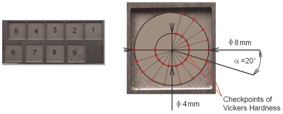
Measuring checkpoints of Vickers hardness on metallographic specimen of experimental sample of tool steel EN X37CrMoV5-1.
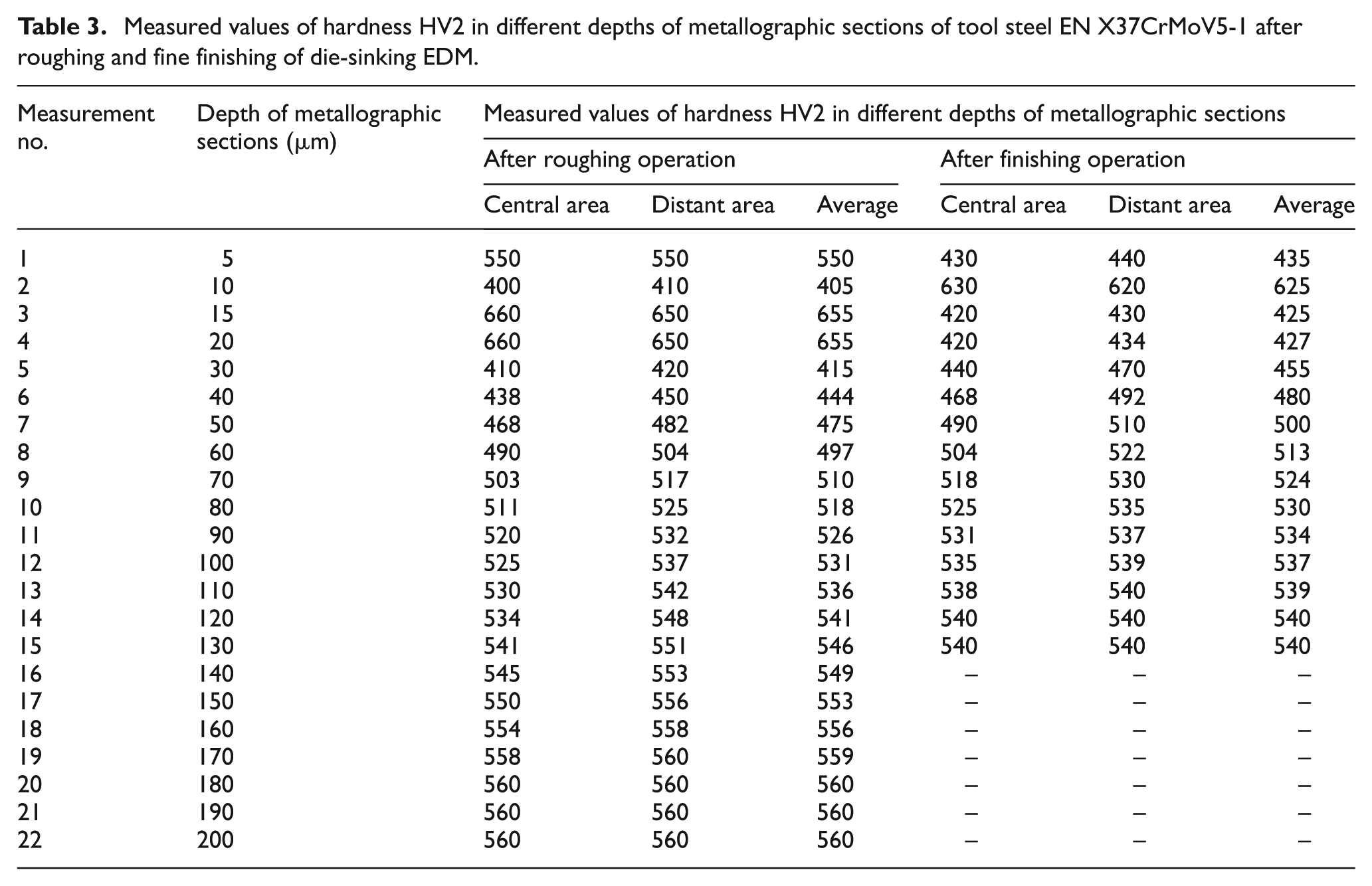
Each pair of pyramid-shaped Vickers indentations represented an increment to the total depth of HAZ in the first phase (four Vickers indentations) by 5 µm and in the second phase by 10 µm up to approximation to the hardness of the BM (a minimum of 16 indentations in roughing and 11 in fine finishing). Measured values are recorded in Table 3.
Measured values of hardness HV2 in different depths of metallographic sections of tool steel EN X37CrMoV5-1 after roughing and fine finishing of die-sinking EDM.
Results and discussions
Evaluation of experimental measurement of the total depth of HAZ and microhardness changes
From Figures 7 and 8, the metallographic snapshot of HAZ of tool steel EN X37CrMoV5-1 recorded by electron microscope with microhardness graph of HV2 can be observed. The graph was constructed based on experimental measurement of microhardness in individual layers of HAZ of samples made by roughing operations so-called powerful cuts and fine finishing operations.
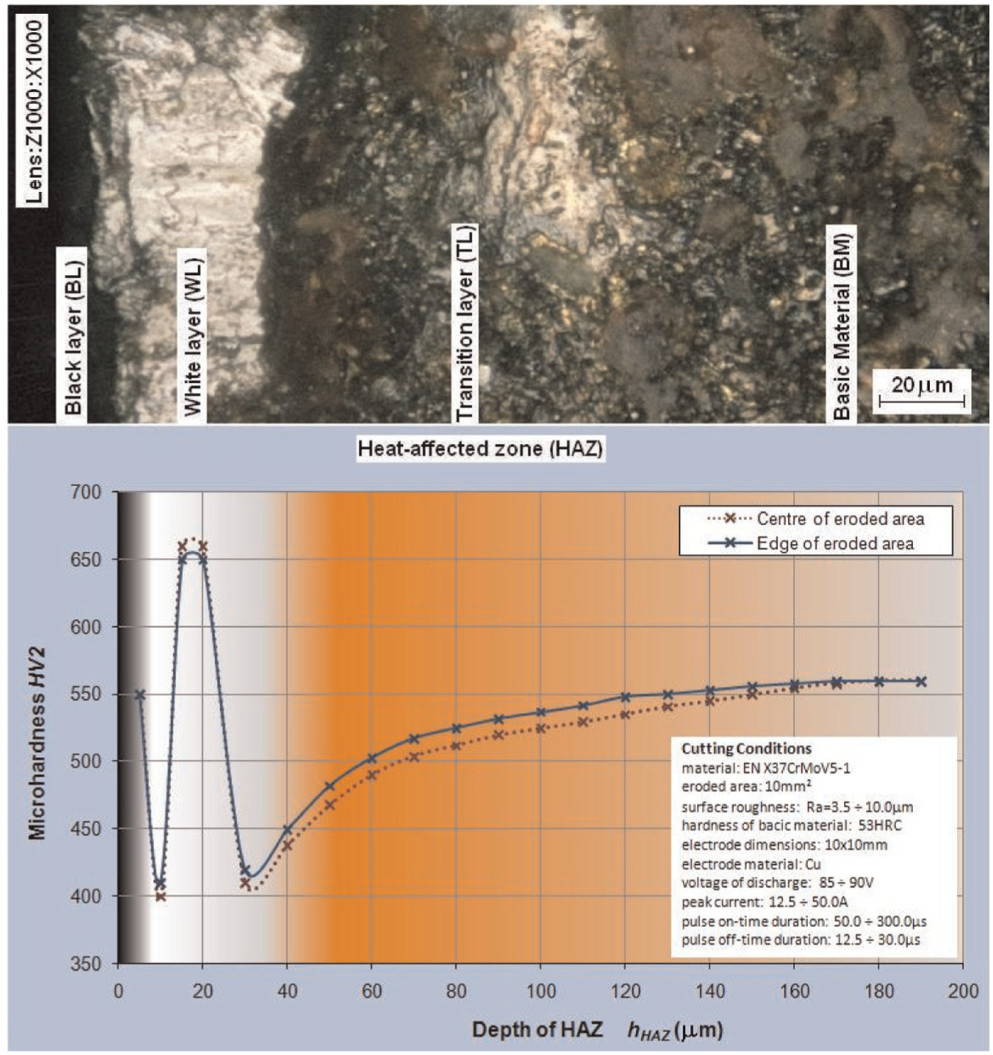
The course of Vickers microhardness HV2 in each heat-affected subsurface layer of tool steel EN X37CrMoV5-1 samples produced by roughing die-sinking EDM.
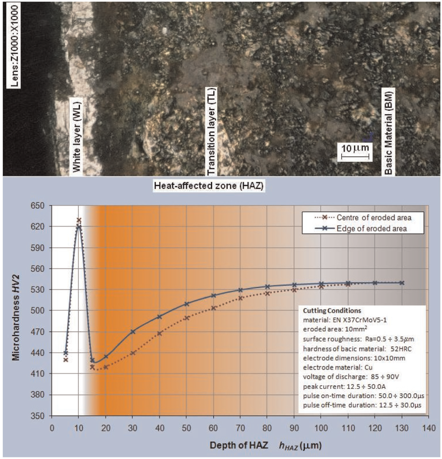
The course of Vickers microhardness HV2 in each heat-affected subsurface layer of tool steel EN X37CrMoV5-1 samples produced by finishing die-sinking EDM.
From Figure 7, it can be observed that a significant Vickers microhardness changes directly on the eroded surface of steel samples EN X37CrMoV5-1 as well as on the tight subsurface layers in comparison with the hardness of the BM 560 HV2 (about 53 HRC). During the experiment, it was demonstrated that the roughing operations are present directly on eroded surface so-called BL. The hardness of this layer is at a level around 550 HV2. Directly under the BL is a layer so-called WL which is characterized by a significant increase of microhardness. Its value was at the level around 650–660 HV2, and the depth was about 30 µm. Another layer represents the TL in which the microhardness is reduced at the level of 410–420 HV2, and gradually from this value, it increases up to BM hardness 560 HV2. The total depth of HAZ was at the level about 160–180 µm. A certain difference in the measured values was recorded between central and distant areas of the eroded surface. From a graph, it can be observed that the TL has in the central area of the eroded surface a gradual increase in microhardness. However, the distant areas show steeper characteristic in TL.
From the graphical representation in Figure 8, it can be observed that the Vickers microhardness changes on the closed subsurface eroded layers of steel samples EN X37CrMoV5-1 in comparison with the hardness of BM 540 HV2 (about 52 HRC). During the experiment, it was demonstrated that the directly on the surface was WL with typical characteristics of Vickers microhardness increase. Its values were from 620 to 630 HV2 and ranged to the depth about 15 µm. Under WL was TL of which microhardness values showed the decrease in the level about 420 to 430 HV2 and sequentially from this value, these increased up to microhardness of BM 540 HV2. The total depth of HAZ was at finishing operation from 80 to 110 µm. From the plot in Figure 8, it can be observed that in TL of eroded surface was gradual microhardness increase in central area, contrariwise, and at distant area, it had the steeper characteristics of microhardness.
On the basis of the realized experimental measurements, it was found that a significant effect on microhardness change and total depth of HAZ has the machining method. Significantly, lower values of total depth of HAZ were recorded for fine finishing operations, where the total depths of HAZ in the range 80−110 µm, contrariwise, and higher values in the range 110−160 µm were achieved for roughing operations. Simultaneously, the curves of microhardness course for fine finishing operations had steeper characteristics than roughing operations. Certain differences were also observed in the WL where microhardness obtains increased values at about 610−660 HV2, while lower values were obtained with fine finishing operations and higher during roughing operations. Also, in the transition area, the substantial differences in gradual microhardness increase can be observed at which the hardness values of BM were attained in the depth ranging 80−160 µm in dependence of machining method. In roughing as well as finishing operations, some differences of measured values between the central and distant areas of eroded surface were observed. Figure 9 shows the graph of experimental measured values of thickness of two basic layers of HAZ, that is, WL and TL, in individual areas of eroded surface of steel samples EN X37CrMoV5-1 in roughing operations so-called powerful cuts and fine finishing operations.
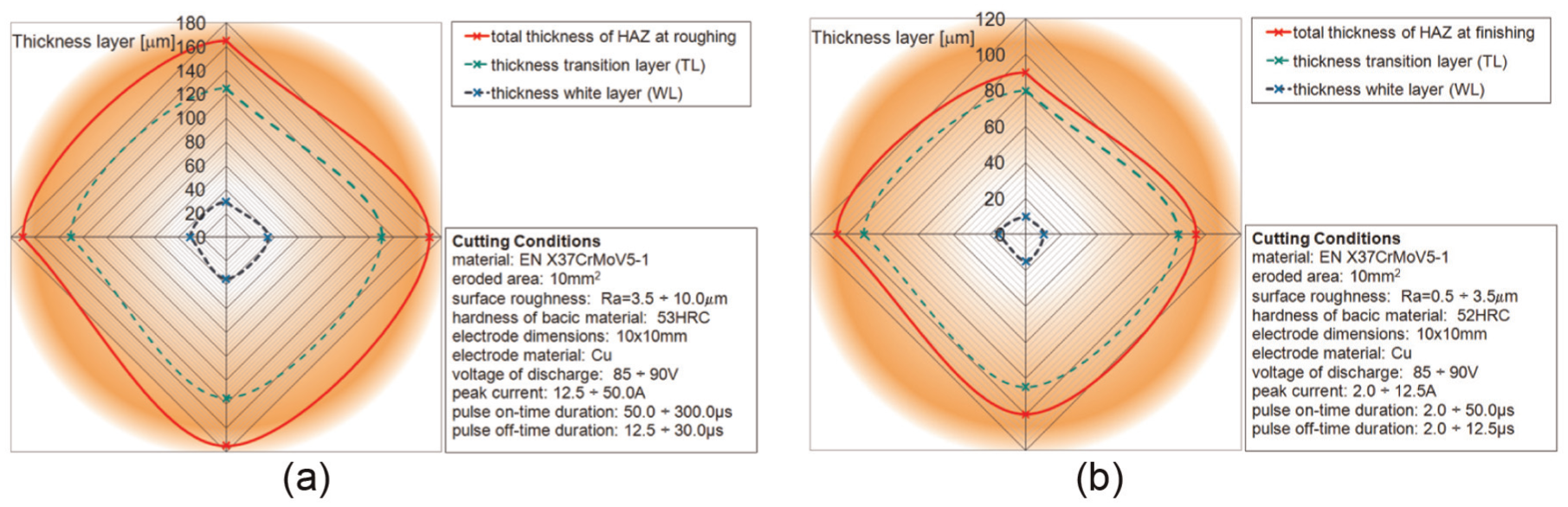
Total thickness of WL and TL in individual area of eroded surface of steel sample EN X37CrMoV5-1: (a) roughing die-sinking EDM and (b) finishing die-sinking EDM.
From Figure 9, the certain differences of microhardness between the central and distant lines of eroded surface can be expected. These variations were obviously caused by excessive overheating of BM in the middle section due to lower intensity of cooling material by dielectric fluid. This effect was not so significant in finishing operations where the intensity of discharge channel was lower. In the experimental samples with total eroded area of 10 mm2, differences in microhardness between central and distant areas up to 10% were obtained, whereby higher values of total depth of HAZ were recorded in the middle part. Whereas the total eroded surface of one sample was 10 mm2, it can be assumed that with increasing eroded surface, these differences will increase.
Mathematical modelling and prediction of the course of the total depth of HAZ
In terms of possible prediction of the resulting surface quality of tool steel EN X37CrMoV5-1 after die-sinking EDM with Cu electrode and in terms of total depth of HAZ, it was necessary to create mathematical and statistic model30,31 which should portray in detail the behaviour of the qualitative parameters of machined surface depending on the setting of the main TP. 32 In practical use of prediction and mathematical−statistical modelling, there is often a problem in identifying the main settings TP. 33 From this perspective, modelling of total depth of HAZ based on qualitative parameters relating to the machined surface roughness is more efficient.
For prediction of total depth HAZ of tool steel after die-sinking EDM with Cu electrode, it was necessary to form the mathematical model using statistical analysis. The least squares method (LSM) seemed to be the most appropriate method because it suitably approximates the tuple of the measured values

In terms of the nature and distribution of experimentally measured values, it was thought with the exponential function (3) with a base of any natural number in the form

while important condition was that the function S(A) expressing the sum of the squares of the differences of calculated and measured values (4) in all cases reached a minimum as
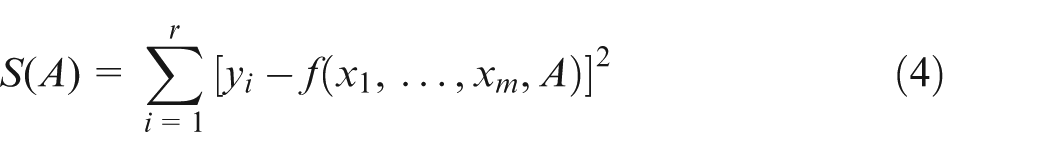
Subsequently, the individual values
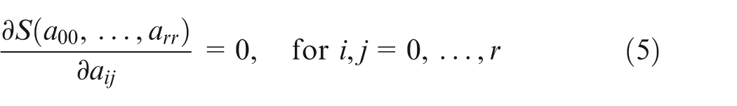
From adjusted partial derivatives, we obtained a system of linear equations whose solutions are searched coefficients.
The quality of replacement of experimentally measured values of each parameter provided that its course describes a regression model. It is expressed by the correlation index (6) which can be determined by the relationship
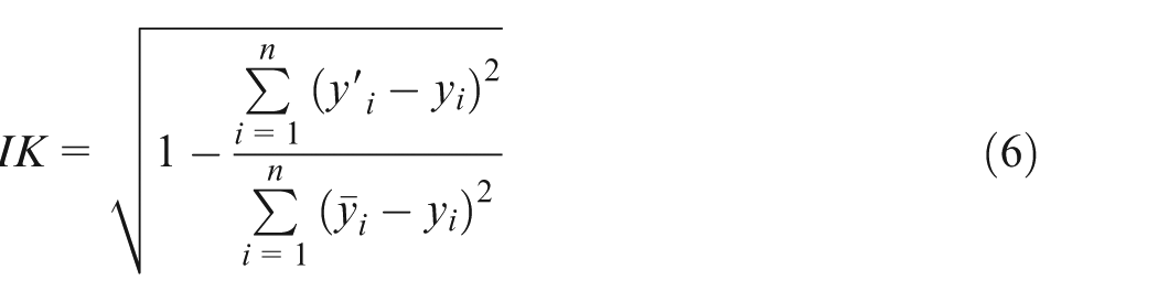
where
As mentioned in the introduction, the total depth of the HAZ is substantially affected by the main TP (peak current I, pulse duration ton, and pulse off-time toff). Compilation of mathematical and statistical model, which predicted the overall depth of the HAZ based on a combination of all the TP, would be impractical. By reason, achieving eroded surface roughness parameters 34 Ra and Rz is directly related to the main TP die-sinking EDM process, and the compilation of mathematical and statistical models was divided into two phases. In the first phase, the mathematical models were constructed for predicting the quality of the machined surface parameters Ra and Rz based on the approximation of the recorded values of TP I, ton, and toff as partial models for predicting the total depth of the HAZ. In the second phase, the mathematical model was constructed for predicting the total depth HAZ based on the quality of the machined surface parameters Ra and Rz as a function of seven variables.
The first phase of mathematical modelling using statistical analysis is as follows:
For Ra based on peak current I and share idling
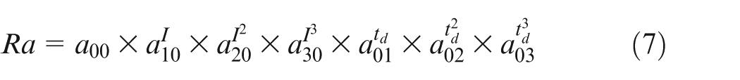
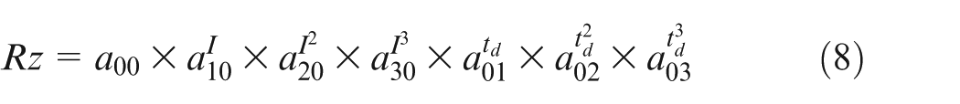
For Rz based on peak current I and share idling
The function of seven variables (9) approximates the tuple of the measured values

where the unknown parameters aij, i, j = 0, …, r are calculated so that the area S(A) approximates the best the measured values. In that case, the relationship (4) can be modified in the form (10)
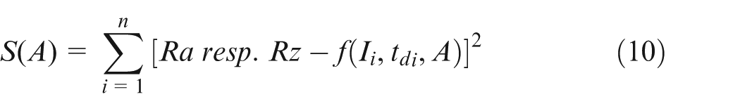
provided that the function reaches a minimum. The unknown is a matrix of variables aij in this case.
The second phase of mathematical−statistical modelling is as follows:
For hHAZ based on quality parameter of surface roughness Ra and Rz of machined surface

which approximates the tuple of measured values

where the unknown parameters aij, i, j = 0, …, r are calculated so that the area S(A) approximates the best the measured values. In that case, the relationship (4) can be modified in the form (13)
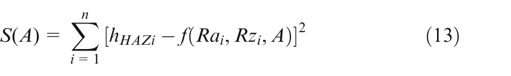
provided that the function reaches a minimum. The unknown is a matrix of variables aij in this case.
Based on measured values of quality parameters of machined surface roughness Ra and Rz of tool steel samples EN X37CrMoV5-1 which were recorded with measuring device Mitutoyo Surftest SJ-400 (Mitutoyo Corporation, Japan) at various values of ‘peak current’I and share idling td with software MS Office Excel using logarithmic approximation ‘logest’ function, it was determined by calculating the partial mathematical models using statistical analysis. The result set of partial mathematical models (14) and (15) is an array of parameter values, which describe these areas in the form
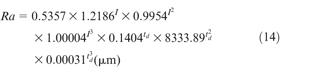
The correlation index is IK2 = 0.9982
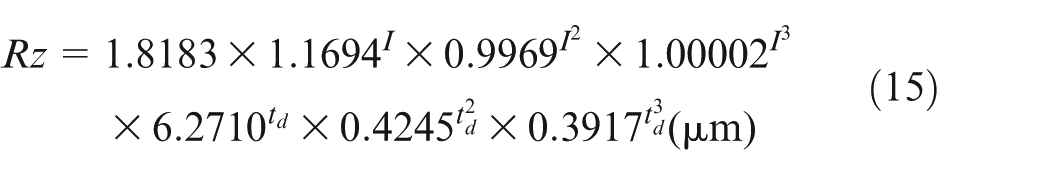
The correlation index is IK2 = 0.9751
where Ra and Rz are the parameters of surface roughness (µm), I is the peak current (A), and td is the share idling
Analogously, the experimentally measured values of total HAZ depth of tool steel samples EN X37CrMoV5-1 at different machined surface roughness values of Ra and Rz was determined by the resulting mathematical model (16) for prediction of hHAZ in the form
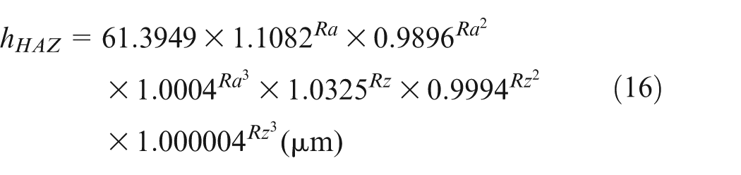
The correlation index IK2 = 0.9991
where hHAZ is the total depth HAZ (µm), and Ra and Rz are the parameters of surface roughness (µm).
Accuracy of the given mathematical models for prediction of the total depth of HAZ shows the correlation index (IK2), which takes the value 0.9991 representing a real deviation from the measured values calculated to 0.2%.
Implementing partial assembled mathematical models (14) and (15) on the simulation programme graphics created three-dimensional (3D) graphic dependences as shown in Figure 10. 3D graphic dependences predict the quality parameters of eroded surface roughness Ra and Rz of tool steel EN X37CrMoV5-1 on mutual combination contemplated TP.
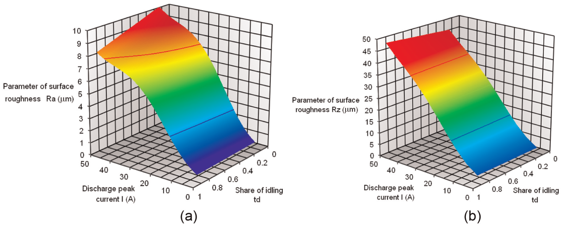
3D dependence simulation of parameters of surface roughness on technological parameters I and td of steel samples EN X37CrMoV5-1 after die-sinking EDM: (a) dependence on parameter Ra and (b) dependence on parameter Rz.
Implementing the resulting mathematical models (16) for the prediction of total depth of HAZ on the simulation programme graphics generated the 3D graphic dependences as shown in Figure 11. These predict the parameter hHAZ of the eroded surface of tool steel EN X37CrMoV5-1 based on the final quality of machined surface in terms of roughness parameters Ra and Rz.
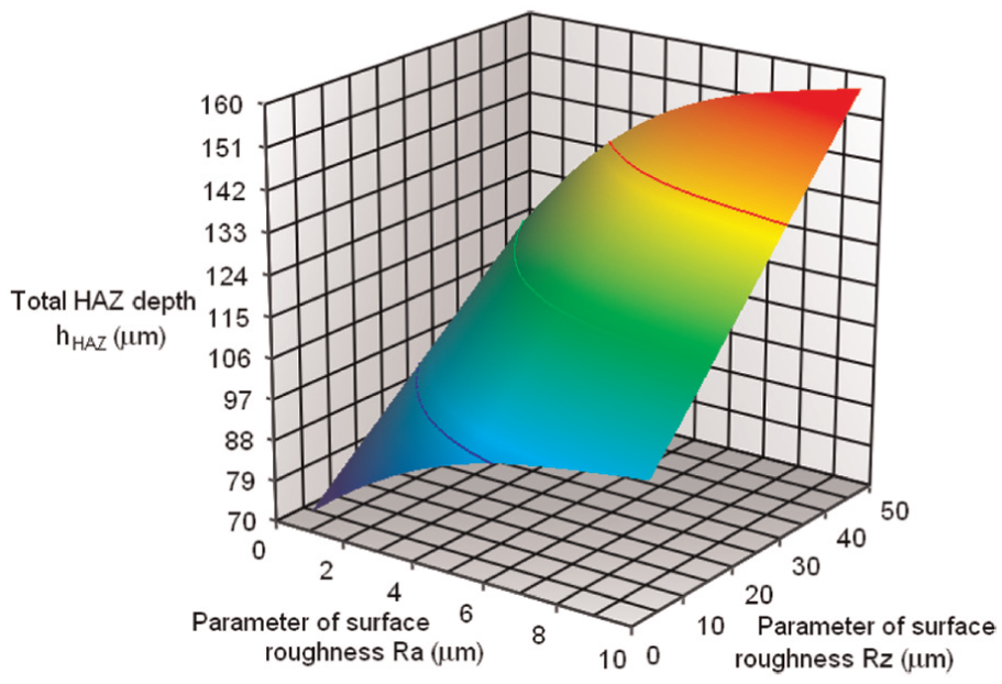
3D simulation of total HAZ depth of tool steel samples EN X37CrMoV5-1 after die-sinking EDM depending on surface roughness parameters Ra and Rz.
Based on experimental assessment of the total depth of HAZ of manufactured samples of tool steel EN X37CrMoV5-1 by die-sinking EDM, slight variations to 10% between central and peripheral parts of eroded surface were observed. 3D graphics shown in Figure 12 shows the increase in total depth of HAZ with increasing eroded surface of tool steel EN X37CrMoV5-1 after die-sinking EDM depending on the size of the Cu electrode used with square section.
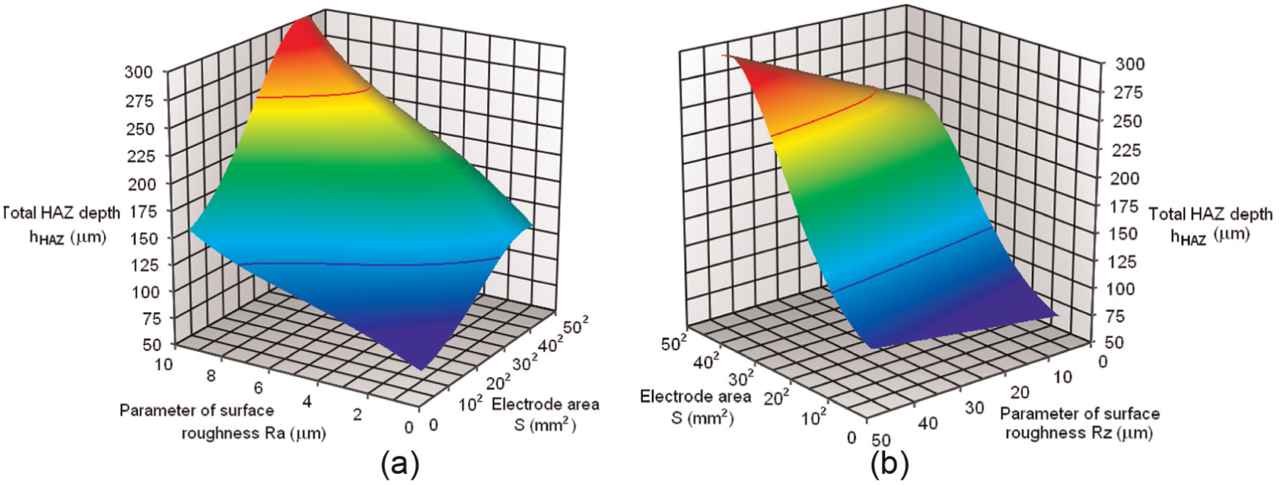
3D simulation of increasing total HAZ depth with increasing cross-sectional eroded surface of tool steel samples EN X37CrMoV5-1 after die-sinking EDM: (a) dependence on parameter Ra and (b) dependence on parameter Rz.
In simulating dimensions of Cu electrode from 10 × 10 mm2 (S = 102 mm2) to 50 × 50 mm2 (S = 502 mm2), the total depth of HAZ will be in range of 70–300 µm depending on setting of main TP values and achieved quality parameters of machined surface Ra and Rz. Lower values of total HAZ depth will be achieved at a smaller dimensions of Cu electrode2,11 and fine finishing operations, while higher values for roughing operations with Cu electrode of larger dimensions.
Recommendations for practice
Based on a detailed inspection of the total depth of HAZ and microhardness changes in subsurface layer, leaned on established mathematical models, it can be concluded that high levels of settings of peak current I and the low shares idling td, respectively, their inappropriate combination, result in a substantial increase in the total depth of HAZ and the negative impact of the microhardness change of the HAZ. However, by optimizing the settings of these TP, it can create surfaces with the desired parameter hHAZ value as well as the required level and microhardness homogeneity. It is important to note, however, that setting the main TP is also necessary to take into account the efficiency and productivity of electrical erosion process. It means that the actual values of setting in the main TP at die-sinking EDM must maximize the quality parameters of machined surface and also to be optimized in terms of maintaining the stability and efficiency of electrical erosion process itself.35,36 A suitable solution can be, for example, setting of higher value of parameter toff about 20%, leading to a reduction in the minimum cutting performance due to reducing share idling td, but a substantial homogenization of the individual values of monitored parameters hHAZ and microhardness HV2 between and central and peripheral parts of eroded surface. Changing the combination of these main TP will increase the time required to cool the subsurface layers of workpiece leading to a smaller extent affect and at the same time to increase the homogeneity of the monitored quality parameters of the HAZ across all eroded surfaces.
Conclusion
The task of the experiment was to carry out detailed research of HAZ in subsurface layers of machined surface after die-sinking EDM of medium-alloyed tool steel EN X37CrMoV5-1 (W.-Nr. 1.2343) with Cu electrode. In the experiment, the various subsurface layers HAZ of eroded surface in terms of their total thickness, range, and also the microhardness changes were considered in detail.
For the achievement of the desired surface quality in terms of parameter hHAZ, it was necessary to create mathematical models that would allow describing the behaviour of the machined surface depending on the main TP setting with respect to the real course of microhardness. These mathematical models were subsequently implemented into the simulation programme which enables to by simulating the optimal combination of main TP with a view to achieving the desired parameter value hHAZ.
Experimental results are summarized in the following points:
By experimental measurement in medium-alloyed tool steel EN X37CrMoV5-1 using Cu tool electrode with functional area up to 10 mm2, the total depth of HAZ was found in the range of 80−110 µm for fine finishing operations and 110−160 µm for roughing operation.
Differences were found between the measured values of the total depth of HAZ in individual parts of eroded surface, whereby the central part to 10 mm2 showed about 10% higher values hHAZ opposite to the peripheral parts.
In the HAZ, the significant variations of microhardness due to BM hardness which was at the level about 540−560 HV were observed. Microhardness in the area called WL showed increased values of approximately 620−660 HV2, whereas in TL, decrease in microhardness to the level about 400−430 HV2 was recorded.
Prediction of the total depth of HAZ based on microhardness change and surface roughness parameters of eroded surface using 3D simulation of combination of each other main TP showed increased values in the eroded surface to 50 mm2 at the level 125 to 300 µm.
The knowledge acquired by the experimental research of the HAZ of eroded surface samples manufactured from medium-alloyed chrome– molybdenum–silicon–vanadium tool steelEN X37CrMoV5-1 has, in terms of microhardness change and total depth of HAZ, significant contribution not only for the theory but also for practice. The solution results will allow to meet the quality requirements more closely to the desired quality of the machined surface in die-sinking EDM with Cu electrode, thereby achieving a higher quality of products manufactured by this advanced technology.
Footnotes
Declaration of conflicting interests
The author(s) declared no potential conflicts of interest with respect to the research, authorship, and/or publication of this article.
Funding
The author(s) received no financial support for the research, authorship, and/or publication of this article.