
Abstract
Ultra-fined grain materials are thermodynamically unstable and when they are exposed to a high external thermomechanical energy, such as electrical discharge machining process, many microstructural changes will occur in them. However, in the electrical discharge machining process, the recast layer and heat affected zone are the undesired and inevitable consequences of this process, which have several adverse effects on the surface layers of the workpiece including microstructural changes, grain growth, alternation of hardness, initiation of micro-cracks and changing the composition. All of which deteriorate the surface integrity. In this article, the effects of the electrical discharge machining process on the ultra-fined grain steel samples have been studied through investigating the microstructure of the recast layer and heat affected zone via scanning electron microscopy, optical microscopy and X-ray diffraction technique. The thickness of the recast layer and heat affected zone as well as the cracks’ density and the hardness profile of the ultra-fined grain samples was measured and the results were compared with coarse grain samples. Results show that the undesired effects of electrical discharge machining process on the ultra-fined grain samples are more considerable than the coarse grain ones; for instance, by comparison with coarse grain samples, relatively thicker recast layer and heat affected zone are formed in the ultra-fined grain samples, in which the microstructure changed more considerably. In addition, on one hand, the more extended cracks on the electrical discharge machined surface of the ultra-fined grain samples were observed, and on other hand, the hardness profile of the ultra-fined grain samples varies more noticeably from the surface to the depth.
Keywords
Introduction
Severe plastic deformation (SPD) methods are widely used to produce ultra-fined grain (UFG) materials recently. 1 The mechanical properties of these materials such as the strength, hardness, toughness and plasticity improve by decreasing the grain size. 2 Literatures show that electrical conductivity and wear resistance are improved by the grain refinement process as well.3–5 Equal channel angular pressing (ECAP) is the most functional SPD process to produce bulk UFG materials that developed by Segal in 1980. 6 In the ECAP process, high strains are imposed to material by extruding the billet through two equal channels, resulting in a dense and fined grain material. 7 Figure 1 shows the schematic view of the ECAP process. Internal (Φ) and external angles (Ψ) are two geometrical parameters of an ECAP die (Figure 1) determining the equivalent strain. Yang et al. 8 studied the influence of geometrical parameters of the ECAP die on the plastic strain of materials.
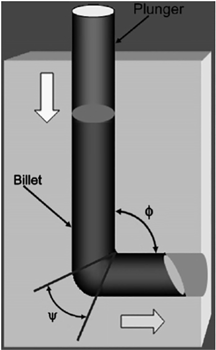
Schematic of the ECAP process.
Iwahashi et al. 9 in 1996 calculated the equivalent strain after N passes of ECAP concluded in the equation as follows
According to Iwahashi equation, by increasing the number of ECAP passes the equivalent strain, the strength of material increases because of piling up and locking the dislocations. However, by increasing the ECAP passes, the elongation and the ductility of materials decrease, 10 though this can be controlled by post heat treatment. 11 Recently, producing industrial parts from the UFG materials becomes widespread. 12 In order to manufacture precise industrial parts out of the UFG materials, finishing machining processes is indispensable. 13 Surface roughness is a significant factor in machining processes.14–16 One of the applicable machining methods is electrical discharge machining (EDM). EDM is used widely to machine electroconductive and semi-conductive materials, regardless of their hardness and other mechanical properties. 17 Complex geometrical shapes such as plastic injection molds, dies and punches can machine by EDM process.18,19 EDM is a thermoelectrical process shaping parts by successive discrete sparks occurring between a tool’s electrode and workpiece, while both of which are immersed in dielectric liquid. These sparks melt the surface layers of the both workpiece and tool, and after flushing away the molten materials, the geometry of the tool is carved on the workpiece. 20 A portion of the molten materials in the melt pool is flushed away by the dielectric, while the remaining molten materials solidify on the surface of the workpiece and form a hard and brittle layer called recast layer. The recast layer due to its physical characteristic and metallurgical structure consists of many cracks and voids and has undesired influences on the mechanical properties and surface integrity of the workpiece.21–24 By comparison with coarse grain materials, the UFG materials have higher grain boundaries’ energy6,25,26 due to SPD and are more prone to the microstructural changes at the surface layers during EDM process.
In this article for the first time, the undesired effects of EDM process on the UFG steel samples including recast layer and heat affected zone (HAZ), micro-cracks, microstructural changes and surface layers’ hardness have been investigated. For this purpose, first, a number of low-carbon steel samples were ECAPed. Then, the both UFG and coarse grain samples were EDMed under identical machining condition. The microstructure, cracks and thickness of recast layer and HAZ of the UFG and coarse grain samples were investigated by scanning electron microscopy (SEM) and optical microscopy (OM). The recast layer phases were identified by X-ray diffraction (XRD) technique. The hardness of the specimens was measured by micro-hardness tester. Finally, the results of the UFG samples were compared with those of the coarse grain samples.
Experimental methodology
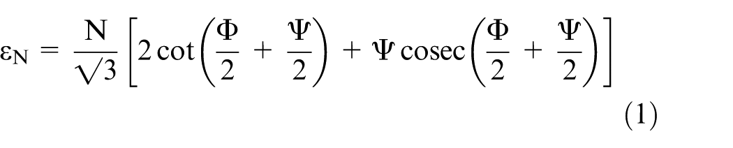
Low-carbon steel was used in this article with the chemical composition shown in Table 1. The dimensions of the cylindrical workpieces were 20 mm diameter and 70 mm height. Samples were ECAPed at room temperature and at the pressing rate of 1 mm/s with molybdenum disulphide (MoS2) as lubricant. The press tonnage was 14 tons. The internal and external angles of the ECAP die were Ψ = 30° and Φ = 90°, respectively. Figure 2 shows the applied ECAP die.
The chemical composition of low-carbon steel.
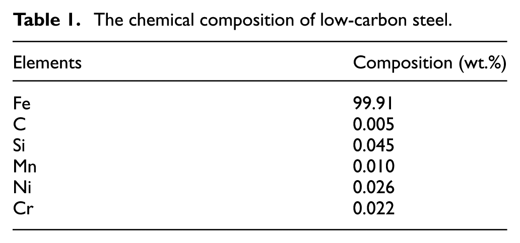
The applied ECAP die.
Then, samples were cut with a Charmilles Robofil 2000 wire cut machine and EDMed with a die-sinking EDM machine–type Charmilles Roboform. The tool electrode was a cylindrical copper shaft (Φ = 30 mm) and dielectric liquid was kerosene. The samples were immersed in the dielectric to a depth of 20 mm. To have enough thickness of recast layer, EDM should be conducted in high current (roughing mode) condition. From this point of view, 1 mm of the samples was EDMed. Table 2 shows the EDM’s parameters.
EDM’s parameters.
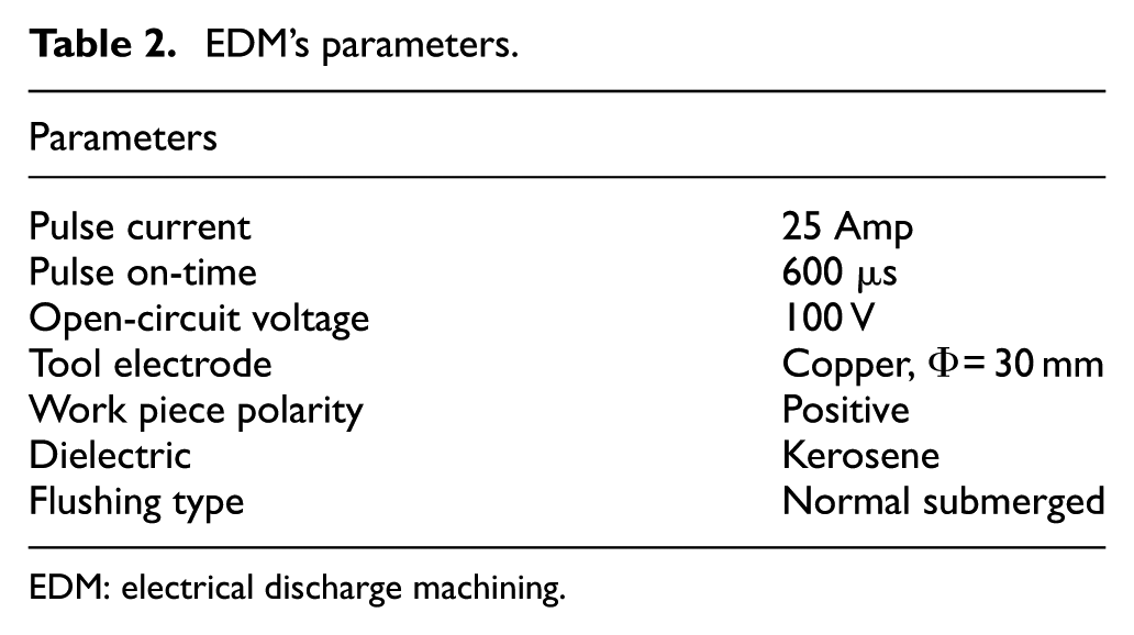
EDM: electrical discharge machining.
In the following, the machined samples were mounted in cold resin epoxy and ground by 2500 grit sandpaper and carefully polished. In order to observe the microstructure and the grain boundaries, the samples were etched with 2% Nital solution. The prepared samples were analyzed by a SEM of VEGA\\TESCAN Company with RONTEC analyzer and an OM of the Olympus Company. Figure 3 shows two prepared and unprepared samples.
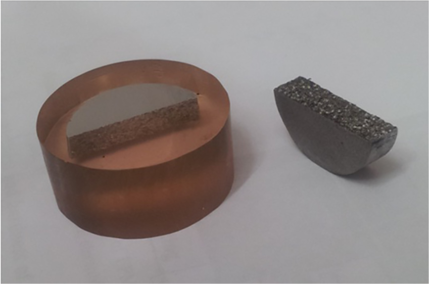
A prepared and an unprepared sample.
To identify the phases of the samples, XRD technique was used. The diffraction patterns were measured from 10° to 100° for 10.3366 s per step with a step of 0.017° and then analyzed by the X’Pert High Score Plus program. The composition has been recognized from the PDF-2 databases.
The hardness of machined samples was measured by a Buehler micro-hardness tester. A 0.05 kg load was applied over 10 s. It is important to note that the samples had been carefully prepared before hardness test.
Results and discussion
Microstructure of recast layer and HAZ
Figure 4 shows the OM images of microstructure of a sample before and after ECAP process. As the OM images show, the grain size has tangibly decreased after ECAP process. The grain size before ECAP process had been 80 µm which was reduced to 3.2 µm after ECAP. The grain size was measured by the Heyn intercept method. Having considered the low carbon content of the steel (0.005 %wt.), the microstructure of the samples consists of mostly ferrite and a little pearlite.
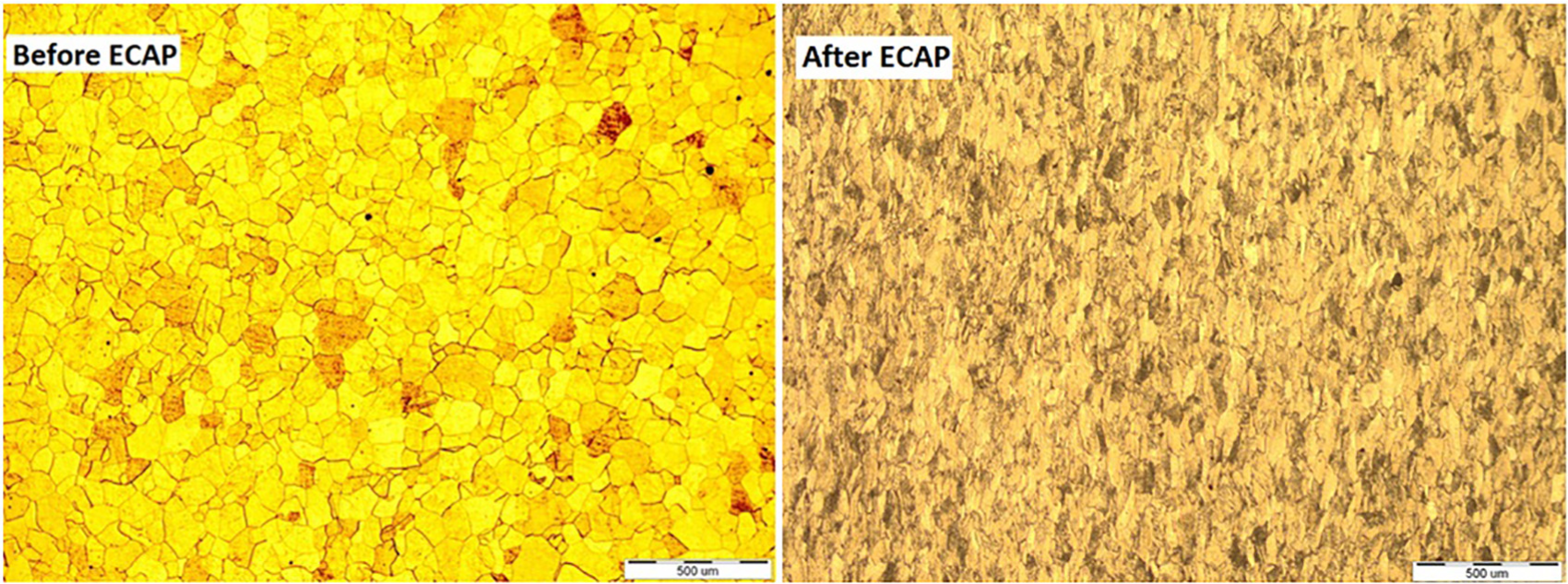
Grain size before and after ECAP.
The metallurgical phase of molten materials in the melt pool is austenite. During EDM process, this austenite is quenched by dielectric liquid and a portion of that transforms into martensite, while the rest remains austenite. Thus, the main phases of the recast layer are martensite and retained austenite. Microstructure of the recast layer and HAZ of the machined specimens were analyzed via SEM and OM images. Figure 5 shows images of the recast layer of an UFG sample. According to Figure 5, three distinguished layers can be identified in the recast layer. The first layer is the upper layer of the recast layer consisting of columnar martensite. This columnar martensite is similar to equiaxial needle structure. The thin and elongated structure of the first layer is due to high cooling rate (about 106 K/s). 27 Heat transfer between the outer layer of the recast layer and the dielectric is convection. The columnar martensite in the first layer grows downward perpendicular to the surface of the recast layer, since the crystal lattice of martensite aligns in the direction of the cooling rate. 27
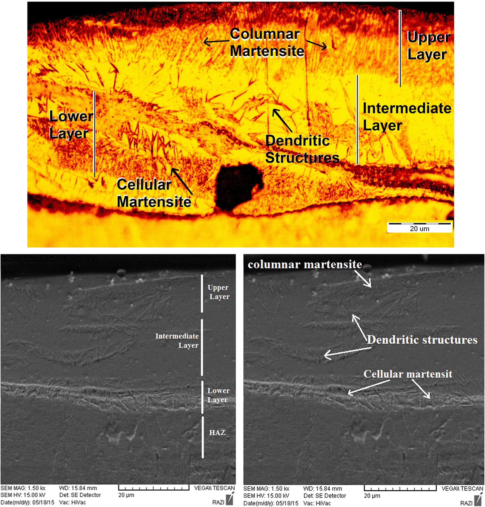
Microstructure of the recast layer of an UFG sample.
The second layer is the intermediate layer. The cooling rate in this layer is lower than that of the upper and lower layers of the recast layer. Thus, the main phase of this section is the retained austenite. The diffusion of the carbon atoms from parent metal and dielectric liquid (kerosene) to the melt pool in solidification process also raises the retained austenite structure in this layer. 28 According to Table 1, the samples’ steel material contains Mn and Ni additives. These elements stabilize the austenite and increase the retained austenite in the second layer. 29 In intermediate layer, several interlocking dendritic structures are observed. 30 Due to lower cooling rate, these featureless structures can be martensite or low bainite. Lath martensite also can be observed in the second and third layers. The iron carbides (cementite) exist in the recast layer because of ingression of the carbon atoms from the dielectric into the melt pool. The intermediate layer is the source of micro-cracks in the recast layer. 28
The third layer is the lower layer and consists of cellular martensite and retained austenite. The heat transfer mechanism between the lower layer and the base metal is conduction and the cooling rate is higher by comparison with intermediate layer. Therefore, the martensite structure is more noticeable rather than intermediate layer. This cellular martensite structure is perpendicular to the interface of the recast layer and HAZ and projects upward through the cooling rate direction. The microstructure of the recast layer and HAZ is presented schematically in Figure 6.
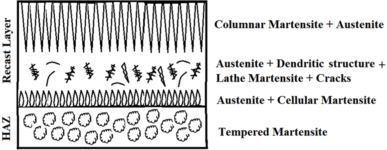
Schematic presentation of the microstructure of the recast layer and HAZ.
Figure 7 shows images of the HAZ microstructure. The HAZ has featureless structure which is difficult to describe;31,32 however, according to Cusanelli survey, it is considered as the tempered lath-shaped martensite. 27 The grain size of the HAZ is greater than the normal grain size in the recast layer. This means that the cooling rate of HAZ is lower than the recast layer, and therefore, the grains have enough time to grow or temper.
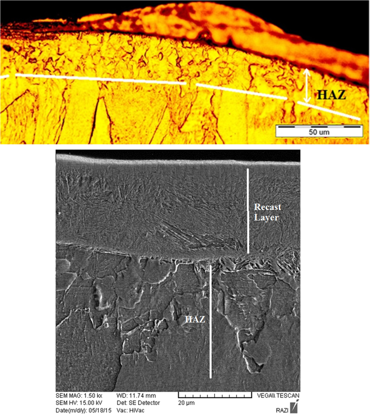
HAZ microstructure of an UFG sample.
Figure 8 shows images of sublayer’s microstructure under the HAZ area. These images show that the sublayer beneath the HAZ is also affected by the heat transferring from the melt pool. Although the phase transformation does not occur, the grains grow in this sublayer. Sidhom et al. 33 also reported similar results. The grains grow by absorbing energy from the EDM process.34,35 This phenomenon in the UFG samples is more noticeable due to high energy of the UFG materials. The UFG materials are thermodynamically unstable. Hence, the metallurgical and structural changes happen more quickly in comparison with coarse grain materials. It should be noted that any structural changes in the UFG materials results in reduction of the favorite mechanical properties such as strength and hardness. Therefore, it is necessary to reduce the undesired effects of the EDM on the UFG materials via controlling the machining conditions.
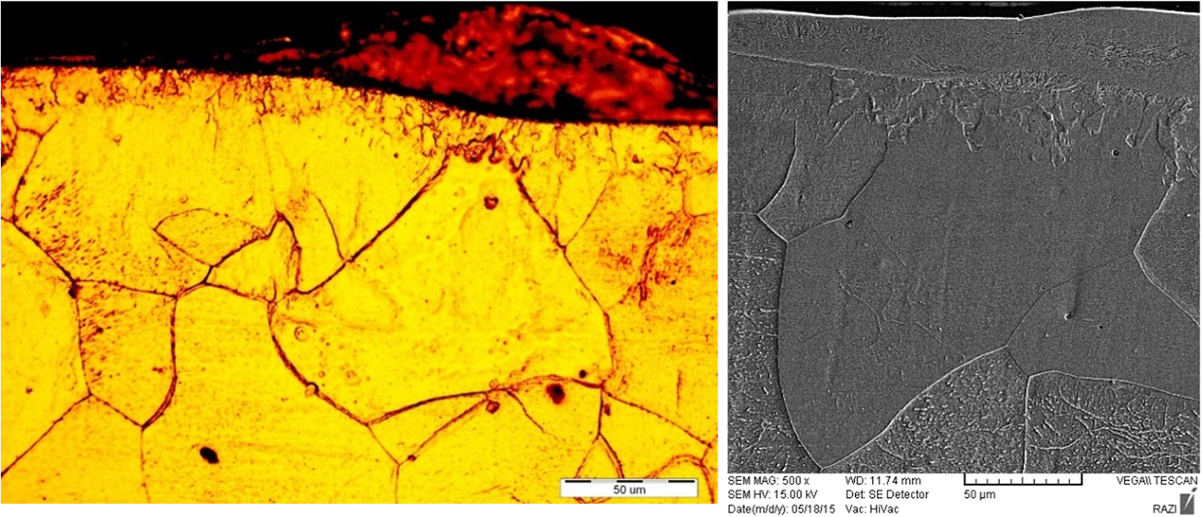
Sublayer microstructure under the HAZ.
The thickness of the recast layer and HAZ mainly depends on machining setup parameters. 30 Generally, the more pulse energy the more thickness of the recast layer and HAZ.36,37 The reason is that the higher pulse energy results in wider melt pool. However, the volume of the melted materials flushed away by dielectric is almost constant. Therefore, by increasing the discharge energy, the more remaining molten material is converted to recast layer. 27 In this survey, machining condition (i.e. I, ton, flushing type) for the both UFG and coarse grain samples was identical. Determination of the thickness of the recast layer is difficult in the roughing mode machining. The thickness of the recast layer varied from 5 to 60 μm. The thickness of the recast layer and HAZ was measured in several points of at least 10 specimens. Figure 9(a) and (b) show the thickness of the recast layer and HAZ in various points of an UFG and a coarse grain sample. The average recast layer’s thickness of the UFG samples was 23 μm and for the coarse grain samples, it was 21 μm. These results imply that the thickness of the recast layer of the UFG specimens is slightly more than coarse grain samples. The reason can be explained by marginal reduction in melting point of the UFG samples due to the grain refinement. 38 In addition, in the same condition, the recast layer thickness increases by decreasing the melting point.36,39 The average thickness of the HAZ in UFG specimens was 19 μm and in coarse grain specimens was 11 μm. This tangible difference proves that the thickness of the HAZ in the UFG materials is greater than coarse grain samples. It can be correlated to the excess energy of the UFG materials. The UFG materials undergo SPD, resulting in the high density of dislocation. This means that the UFG materials are thermodynamically unstable and they are prone to phase transformation in lower temperature.40–42 According to the definition of HAZ, HAZ is the transformed phase of the base metal as a result of the heat transfer from the melt pool to the sublayers. 43 Consequently, the HAZ area in the UFG materials is wider than that of the coarse grain materials.
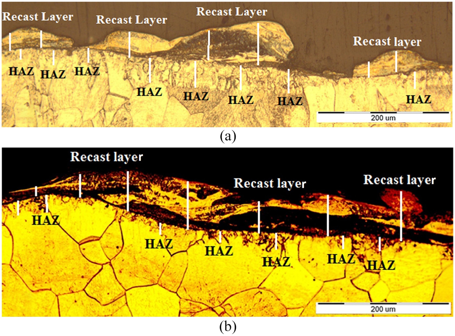
Thickness of the recast layer and HAZ of (a) UFG sample (b) coarse grain sample.
Figure 10(a) shows the XRD profiles of the surface of an UFG sample. The ferrite phase composed the main structure of this sample. As mentioned before, due to low carbon content of steel samples, ferrite and a little cementite was detected in the structure of the hypo-eutectic steel of the samples. Figure 10(b) shows the XRD profile of the surface of an EDMed UFG sample. Martensite was the predominant phase of its structure. As it was showed previously, the structure of the upper layer of the recast layer was martensite and iron carbides. The iron carbides detected in the structure of the recast layer is shown in Figure 10(c). In the UFG steel samples, due to diffusion of the more carbon atoms into the melt pool, the more iron carbides such as Fe3C, Fe5C2 and Fe2C can be detected.
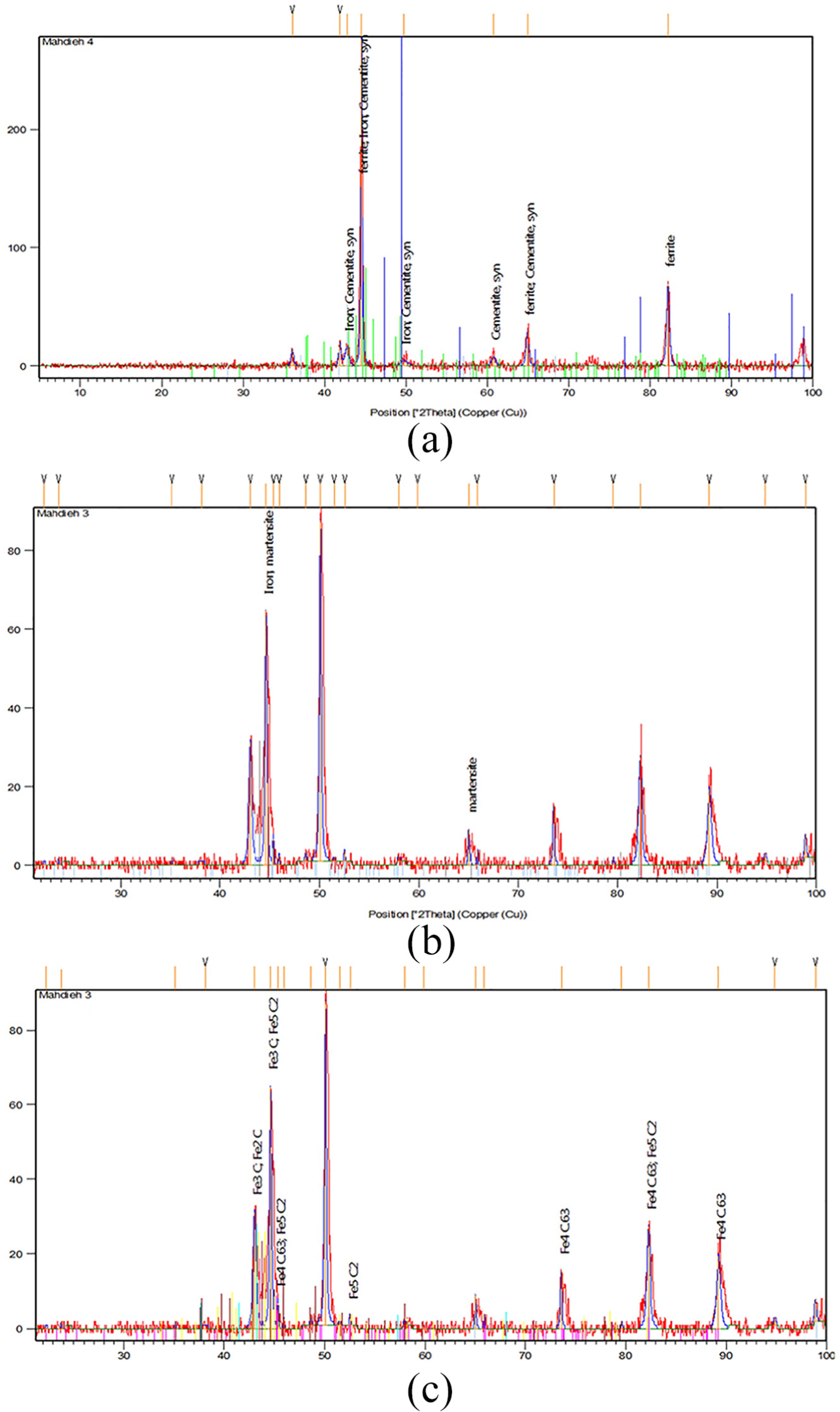
(a) XRD profile of the surface of an UFG sample, (b) an ED machined UFG sample and (c) iron carbides detected by XRD technique on the surface of an ED machined UFG sample.
Cracks
Micro-cracks are an unwanted consequence of electrical discharge machining process that reduces the fatigue strength and surface quality. Figure 11 shows images of the cracks in the recast layer of ED machined samples. The direction, the penetration depth and the density of the cracks depend on machining condition and workpiece properties. Most of the cracks travel perpendicular to the machined surface, but a number of which travel parallel to the surface through recast layer (Figure 11). This type of crack is more noticeable, because the whole section of the recast layer above the crack can be detached from the workpiece. 30 Figure 12 shows SEM images of a crack on the machined surface of an UFG sample. The total length of the cracks (μm) in a unit area (μm2) is a common formula to quantify the cracks’ density. 36 Pulse current (I) influences cracks density, while pulse on-time (ton) affects the length (depth of penetration) of the cracks.44,45 Flushing type and dielectric also have effects on the cracks.28,46 In this work, in order to study the effects of the grain refinement on the cracks formation, all of the machining parameters were kept analogous for both the UFG and coarse grain samples. The average cracks density for 10 UFG and coarse grain samples was measured and calculated. The average cracks density was 1.1 (μm/μm2) for the UFG samples and was 0.7 (μm/μm2) for the coarse grain samples. It proves that the UFG materials are more susceptible to cracks propagation during EDM process. This can be explained by greater hardness of UFG materials. UFG materials are hard and brittle. Hence, cracks initiate and propagate faster in the brittle materials. 47 Moreover, diffusion in the UFG materials happens more rapidly rather than the coarse grain materials. 6 Thus, much more carbon atoms defuse in the melt pool from dielectric liquid (kerosene) during the EDM process. The more carbon ingress, the more hardness of recast layer 48 and eventually, the higher cracks density.
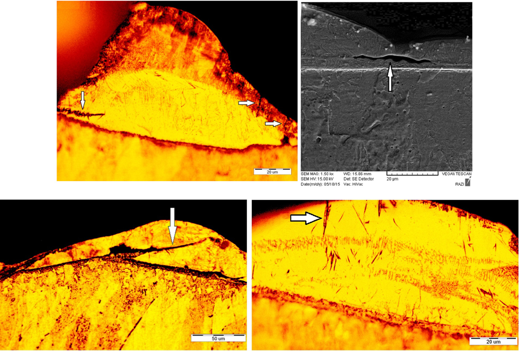
Cracks in the recast layer of UFG samples.
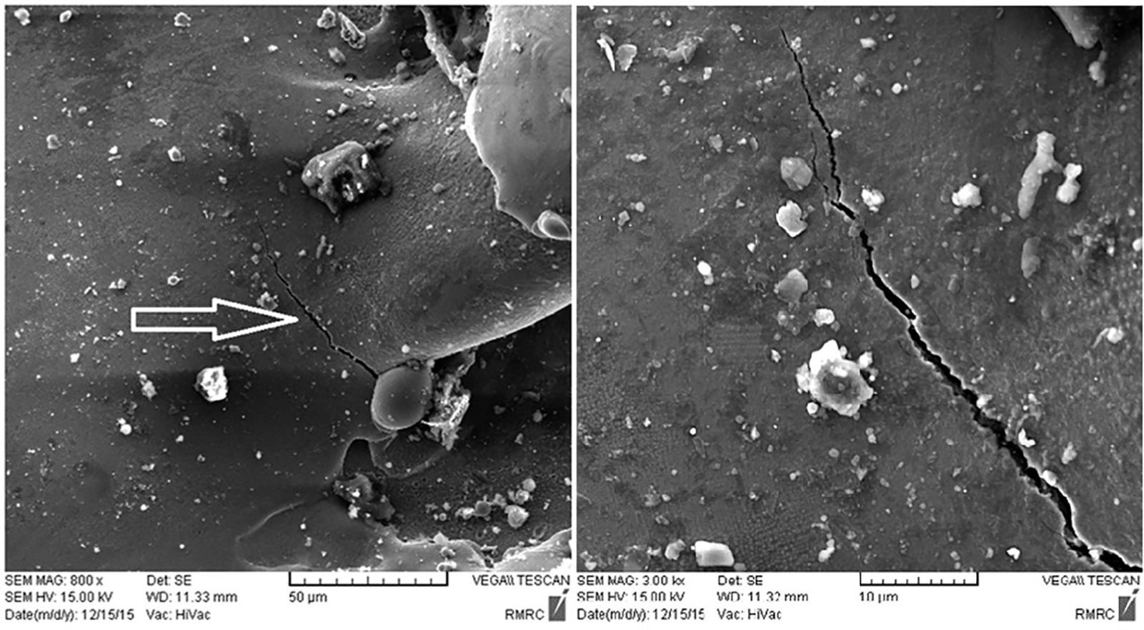
SEM images of a crack on the machined surface of an UFG sample.
In addition, due to high energy of the UFG materials, the phase transformation occurs more rapidly and at lower temperature. When the ferrite crystal transforms to the austenite crystals, indeed the body-centered cubic (BCC) lattice converts to the face-centered cubic (FCC) lattice. This causes contraction in the metal structure. Moreover, when the austenite transforms to the martensite, the FCC lattice converts to the body-centered tetragonal (BCT) lattice. The BCT lattice of the martensite is elongated because of the ingress of the carbon atoms. Thus, conversion of the FCC to the BCT causes expansion in the metal structure. These consecutive expansion and contraction in the crystal structure of material result in the cracks initiation. The UFG materials are thermodynamically unstable and they are more prone to phase transformation as well as undergoing much more structural expansion and contraction, by comparison with coarse grain materials. Therefore, the cracks density is more considerable in the UFG materials during EDM process.
Micro-hardness
The micro-hardness of more than 10 EDMed UFG and coarse grain samples was measured in several points of the recast layer, HAZ and base metal. Figure 13 shows the locations of a series of the indentations on the cross section of a sample. The hardness profile through the cross-sectional surface of the UFG and coarse grain specimens was depicted after carefully measuring the micro-hardness and averaging the obtained data. Figure 14 shows the hardness profile of the UFG and coarse grain ED machined specimens. As the hardness profile (Figure 14) shows, the hardness of the recast layer decreases at the intermediate layer, but increases at the lower layers. This means that the upper and lower layers have higher hardness rather than the intermediate layer. It is in accordance with the results of Zhang et al. 48 and also with the results of Gostimirovic et al. 31 This phenomenon can be explained by the microstructure of the recast layer at the intermediate layer. Retained austenite is the predominant phase of the intermediate layer which is softer than martensite. The hardness of upper layer with the columnar martensite in the recast layer is slightly greater than lower layer with the cellular martensite structure.
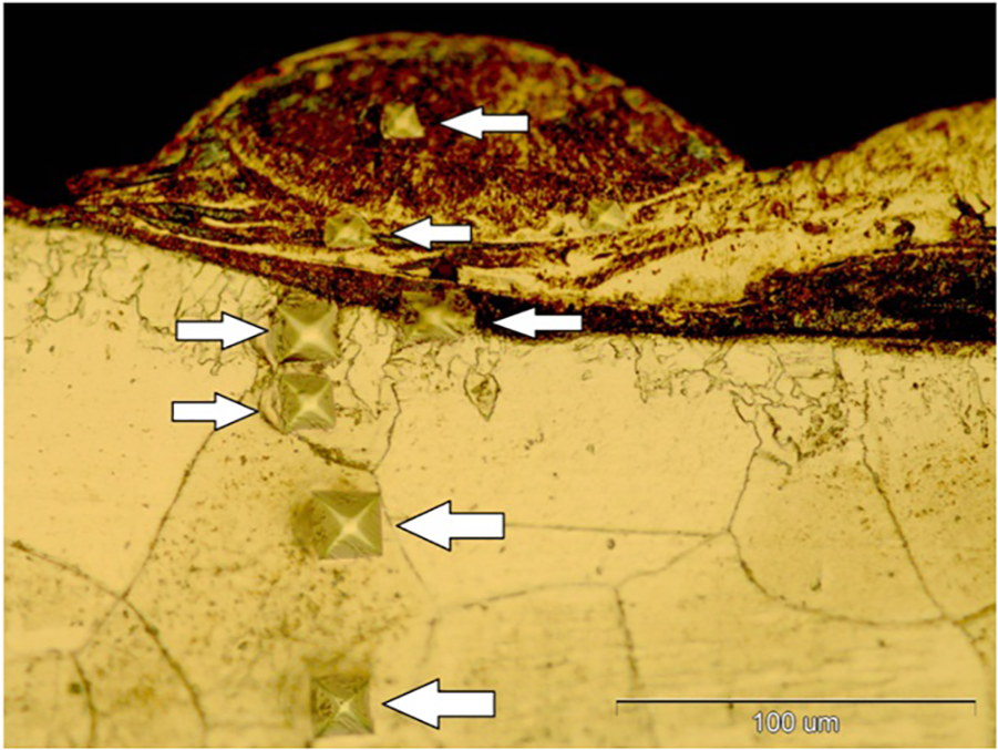
Series of indentations on the cross section of an UFG sample.
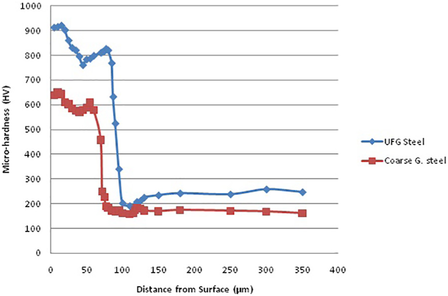
Hardness profile of the UFG and coarse grain samples.
The hardness of the recast layer in the UFG samples was higher than coarse grain samples. The reason is the diffusion of carbon atoms from dielectric into the melt pool during EDM process. The ingress of the carbon atoms in the recast layer results in increasing the hardness. 44 It is well known that the diffusion action occurs more rapidly in the UFG materials. Thus, the diffusion of the carbon in the melt pool of the UFG samples is more rapidly than coarse grain samples. Consequently, the recast layer of the UFG materials is harder than coarse grain materials. Another reason is that the austenite with refined grain size composes a martensite with smaller crystals and harder structure. 29 Therefore, the EDMed UFG materials have harder recast layer.
The hardness profile had a steep decline at the HAZ section for both the UFG and coarse grain samples. 49 The hardness of the HAZ was even less than the base metal in the UFG samples. This can be attributed to the microstructure of the HAZ which is tempered martensite with higher ductility and lower hardness. Finally, the hardness of base metal in the UFG specimens was greater than coarse grain samples due to the grain refinement process.
To sum up, the results of this study are categorized in Table 3.
The final results.
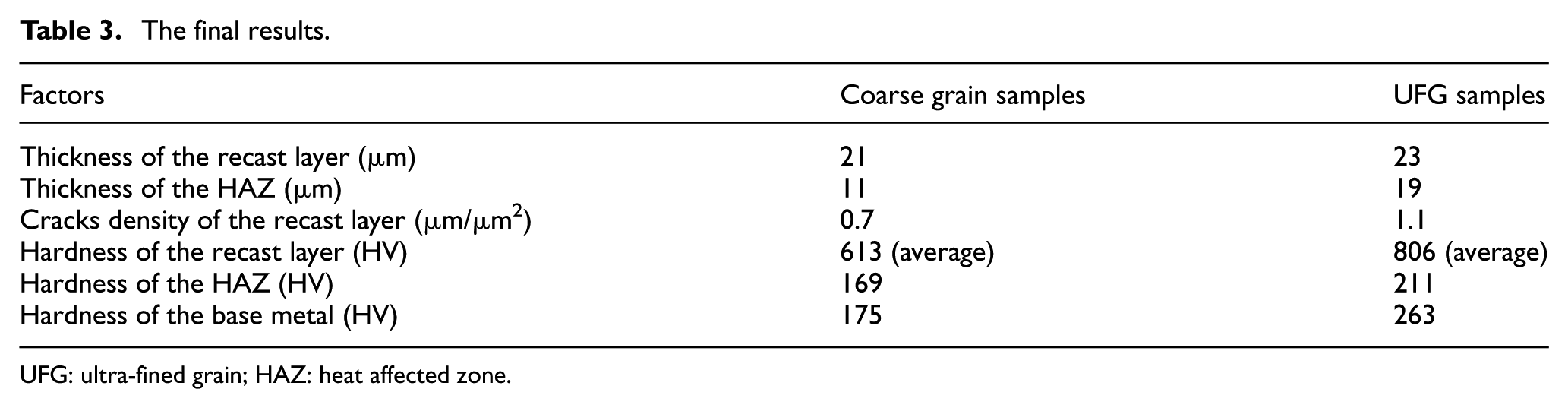
UFG: ultra-fined grain; HAZ: heat affected zone.
Conclusion
In this article, the effects of EDM process on the microstructure and surface integrity of the UFG steel samples have been investigated. The results are as follows:
The layers of the recast layer are chilled through different cooling rates; as a result, three individual sublayers form the recast layer in the UFG steel samples. Upper layer consists of columnar martensite and retained austenite, while the intermediate layer has dendritic structure and the lower layer is formed by cellular martensite and retained austenite. It is worth mentioning that the average thickness of the recast layer slightly increases in the UFG samples (approximately by 2 μm).
The cooling rate in the HAZ is lower than the recast layer. Therefore, the tempered martensite is the main microstructure of the HAZ. In addition, the grains’ growth is observed in the HAZ of the UFG steel samples resulting in reduction of the hardness of the HAZ. Moreover, due to the high internal energy in the UFG materials, the thickness of the HAZ of the UFG samples is greater than that of the coarse grain samples.
The cracks’ density in the UFG samples (1.1 μm/μm2) is higher than coarse grain samples (0.7 μm/μm2). The brittle structure and high internal energy of the UFG materials are the major factors in initiation and propagation of the cracks in the UFG samples.
By comparison with the coarse grain samples, the austenite formed in the recast layer of the UFG steel samples has finer grains resulting in higher hardness (approximately 200 HV).
Footnotes
Acknowledgements
The authors are grateful to the Research Council of Shahid Chamran University of Ahvaz for financial support.
Declaration of conflicting interests
The author(s) declared no potential conflicts of interest with respect to the research, authorship, and/or publication of this article.
Funding
The author(s) disclosed receipt of the following financial support for the research, authorship, and/or publication of this article: This work is financially supported by the Research Council of Shahid Chamran University of Ahvaz (SCU.EM98.39184).