
Abstract
Electrical discharge machining is used in the machining of complicated shapes in hardened molds and dies. In rough die-sinking stage, attempts are made to enhance material removal rate with a consequential reduction in cycle time. Powder mix and ultrasonic assistance are employed in the electrical discharge machining process to create gap conditions favoring material removal. In the present work, experiments are carried out on hardened D3 die steel using full-factorial design based on three levels of voltage, current and pulse on time. The gap phenomena in graphite powder-mixed and ultrasonic-assisted rough electrical discharge machining are studied using a detailed analysis of pulse shapes and their characteristic trains. Two new parameters, namely, energy expended over a second (E) and performance factor (PF) denoting the ratio of energy associated with sparks to total discharge energy, bring out gap conditions effectively. In comparison with the conventional electrical discharge machining for the selected condition, it is seen that the graphite powder mixed in the dielectric enhances the material removal rate by 20.8% with E of 215 J and PF of 0.227, while these values are 179.8 J and 0.076 for ultrasonic-assisted electrical discharge machining with marginal reduction of 3.9%. Cross-sectional images of workpieces also reveal the influence of electrical discharge machining conditions on the machined surface. The proposed approach can be extended to different powder mix and ultrasonic conditions to identify condition favoring higher material removal.
Keywords
Introduction
Electrical discharge machining (EDM) is widely used in die-sinking operation of molds and dies in hardened condition. Material removal takes place due to intense heating and expulsion of molten metal when momentary discharges known as sparks occur at random locations across tool and work surfaces. The nature of dielectric in the gap and closeness of the surface peaks decide the locations at which the sparks strike. If the gap conditions lead to continuous discharge, then arcing occurs. The narrow electrode gap is a major hurdle for any direct observation or measurement. The voltage and current pulse trains captured during the EDM process effectively reflect the gap phenomena and hence throw light on the performance of EDM for different process parameters. Several researchers have studied pulse trains with a view to control the process and achieve consistent performance.1–3 While performance of pulse generator–based EDM was the focus of many researchers, Gangadhar et al. 4 analyzed the relaxation circuit–based EDM. Çoğun 5 made a different approach by grouping the pulses and attempted to relate them to the material removal. A few other attempts were made to characterize the pulse shape by fuzzy theory 6 and waveform analysis. 7 Since intense arcing adversely affected the process as well the integrity of the surface, attempts were also made to study the arcing conditions through statistical analysis and control the process. 8 Several researchers have developed input–output models for different responses such as material removal rate (MRR) and surface roughness. Statistical and artificial intelligence–based techniques have been mostly used to develop such models from the experimental data. Rajurkar and Wang 9 have modeled the EDM process considering its stochastic nature with a view to control the process. Kunieda et al. 10 have documented different research issues in EDM in a systematic way. Since the performance of die-sinking EDM differs in roughing and finishing regimes, authors have also analyzed the pulse shapes and characteristics in these domains and the results of the work have been communicated to a journal. 11
Several researchers have investigated the effect of powder addition in the dielectric medium on MRR in die-sinking EDM. It is reported that the presence of powder in the dielectric medium has a considerable influence on MRR. The possible explanation is that the powder particles suspended in the dielectric medium act as nucleation sites within the electrode gap and promote discharge phenomenon. The powders used vary from conductive to non-conductive powders. Use of different dielectric medium, different powder sizes and different concentrations has been investigated by many researchers. In an earlier study, Jeswani 12 used kerosene mixed with graphite powder as a dielectric medium and studied the feasibility of improving the process performance. Other researchers followed this approach and used different conductive powders such as aluminum powder, 13 aluminum and graphite powders, 14 titanium powder,15,16 graphite powder, 17 and chromium powder 18 for different tool–work material combinations. Use of silicon carbide and aluminum oxide powders, 19 mixture of graphite and boric acid powders, 20 silicon powder,21,22 and carbon nanotube 23 has also been reported in the literature. Since it is not feasible to store dielectric with different powder sizes and concentrations, a specific combination of size and concentration of powder material is preferred in practice. Apart from enhancing the MRR, powder-mixed EDM can also be used to modify the surface and sometimes even to deposit desired materials under certain conditions. A good review of powder-mixed EDM can be found in conference proceedings 24 and journal publication. 25
Attempts are also made to superimpose ultrasonic vibration in the die-sinking EDM and study the effect on its performance. Again, the possible explanation on the role of ultrasonic vibration is that the debris created during the discharge phenomenon is effectively removed from the electrode gap before it is deposited on the work surface. Murthy and Philip 26 recorded the pulse trains, identified the pulse types from the plots and showed that introduction of ultrasonic vibration did affect the pulse types. Kremer and colleagues27,28 studied basically the effect of ultrasonic vibration on die-sinking EDM’s performance in terms of surface integrity and extended the work to study the feasibility of synchronizing the vibration and pulse generation signals. In some attempts, combined effect of powder mix and ultrasonic assistance has been investigated. 29 Recently, Shabgard and Alenabi 30 have carried out ultrasonic-assisted EDM of Ti-6Al-4V alloy in both roughing and finishing regimes. A number of researchers have investigated the ultrasonic-assisted EDM over the past several years, and a comprehensive review will be useful to appreciate the developments. 31
It is seen that a direct observation of gap phenomena in die-sinking EDM is not possible due to the narrow gap existing between the electrodes. Most of the attempts to study the conventional, powder-mixed and ultrasonic-assisted EDM are therefore directed to the study of MRR, surface-generated and associated output responses. Though there are attempts to study the pulse trains in conventional die-sinking EDM, to the best of authors’ knowledge, attempts have not been made to investigate the pulse trains when the powder is added to the dielectric medium or ultrasonic vibration is superimposed during die-sinking EDM process.
In the present work, material removal performance is investigated in the presence of graphite powder in the dielectric and ultrasonic vibration for the experimental conditions identified in the conventional rough die-sinking EDM. The voltage and pulse trains are analyzed using a novel thresholding approach to bring out the characteristics and types of pulses. The performances of the powder-mixed dielectric and the ultrasonic-assisted EDM are compared on the basis of two newly defined parameters, namely, energy expended over a second (E) and performance factor (PF). The performance of these two EDM processes in relation to the conventional EDM for a specific combination of rough machining parameters is also discussed.
Experimental details
EDM experiments are conducted on Electronica ZNC EDM machine with DC pulse generator (Figure 1) having specifications given in Table 1. To conduct experiments with powder-mixed dielectric, a separate container fabricated using mild steel sheet is kept inside the main container provided on the EDM machine. This separation is done to prevent contamination of the dielectric available in the main tank. A limited quantity of powder-mixed dielectric is circulated through a separate line using a separate pump of 1.5 HP. The schematic diagram of the experimental setup with pump and accessories such as pressure gauge, T-connector and valve is shown in Figure 2. The EDM oil mixed with the conductive graphite powder is used as the dielectric fluid. From the literature, it is found that the inter-electrode gap is in the range of 10–100 µm or more depending on the dielectric used and precision required. 10 In certain experiment, graphite powder size of 10 µm is taken and the concentration in dielectric is varied from 0.25 to 6.0 g/l to study the material removal in steel workpieces. 12 Since very large size powder particles can bridge the electrode surface and cause short circuiting, it is reasonable to keep the powder size within 20%–30% of inter-electrode gap. Therefore, in the present EDM work, graphite powder having 25 µm size and concentration of 2 g/l in the lower range is selected, as the aim of present work is to study the changes in the pulse characteristics when the powder is added. The powder-mixed dielectric fluid is supplied into the electrode gap with a pressure of 0.7 kgf/cm2. The dielectric level is maintained in the container by way of additional flow from the top. The dielectric flowing out from the bottom of the container gets pumped back to the nozzle and the container in proper proportion. An interesting point to note is the absence of storage tank for powder-mixed dielectric, as the entire volume of powder-mixed dielectric is in the circulation.
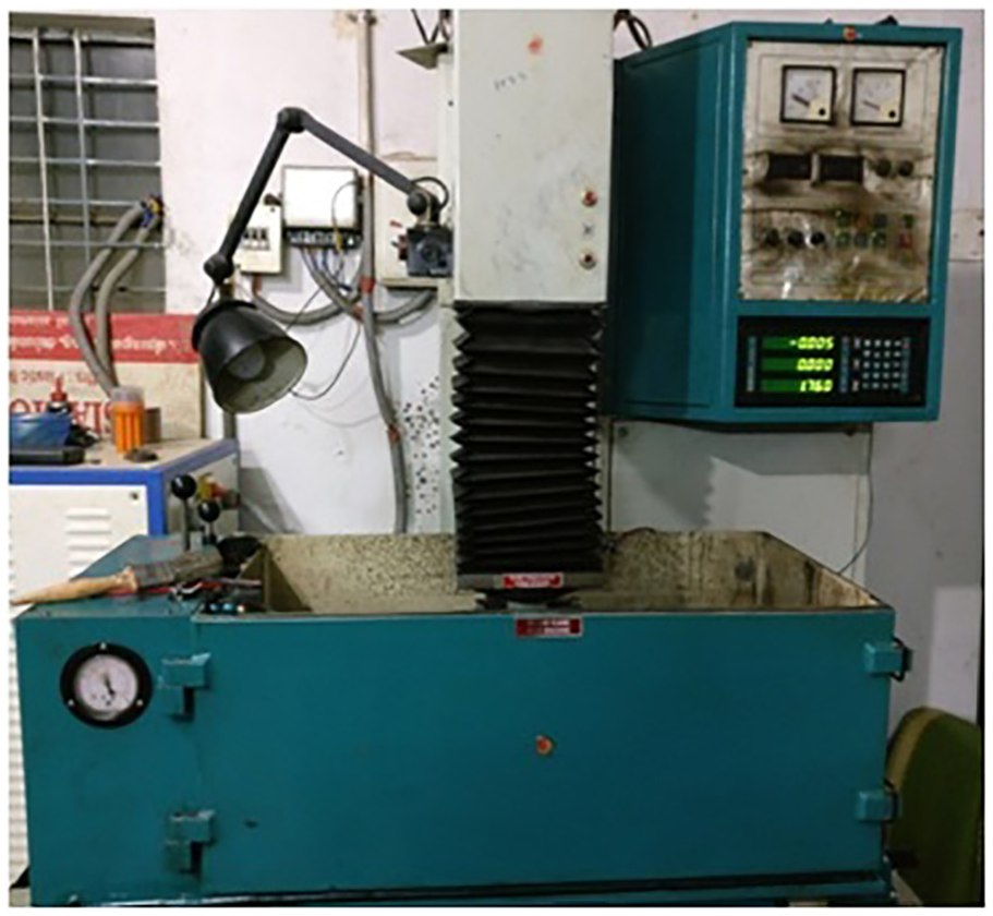
EDM machine used in the present work.
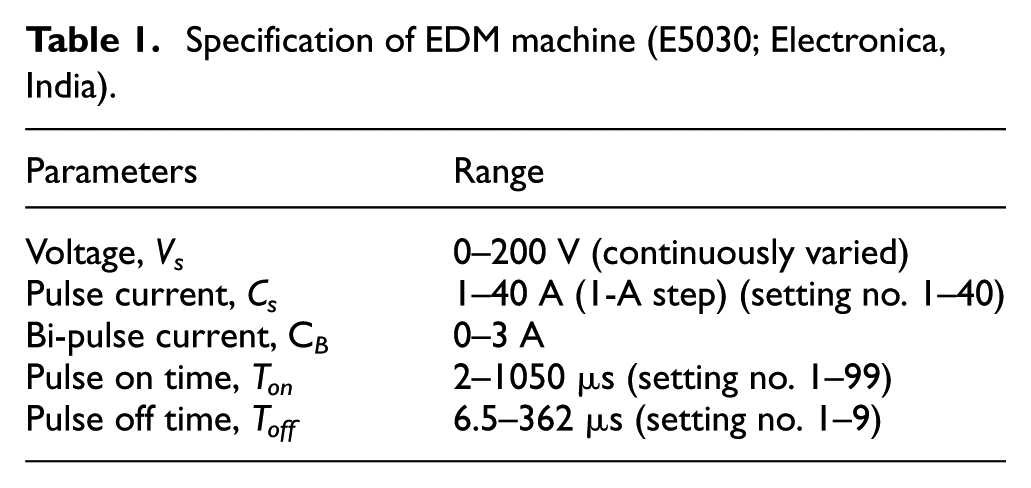
Specification of EDM machine (E5030; Electronica, India).
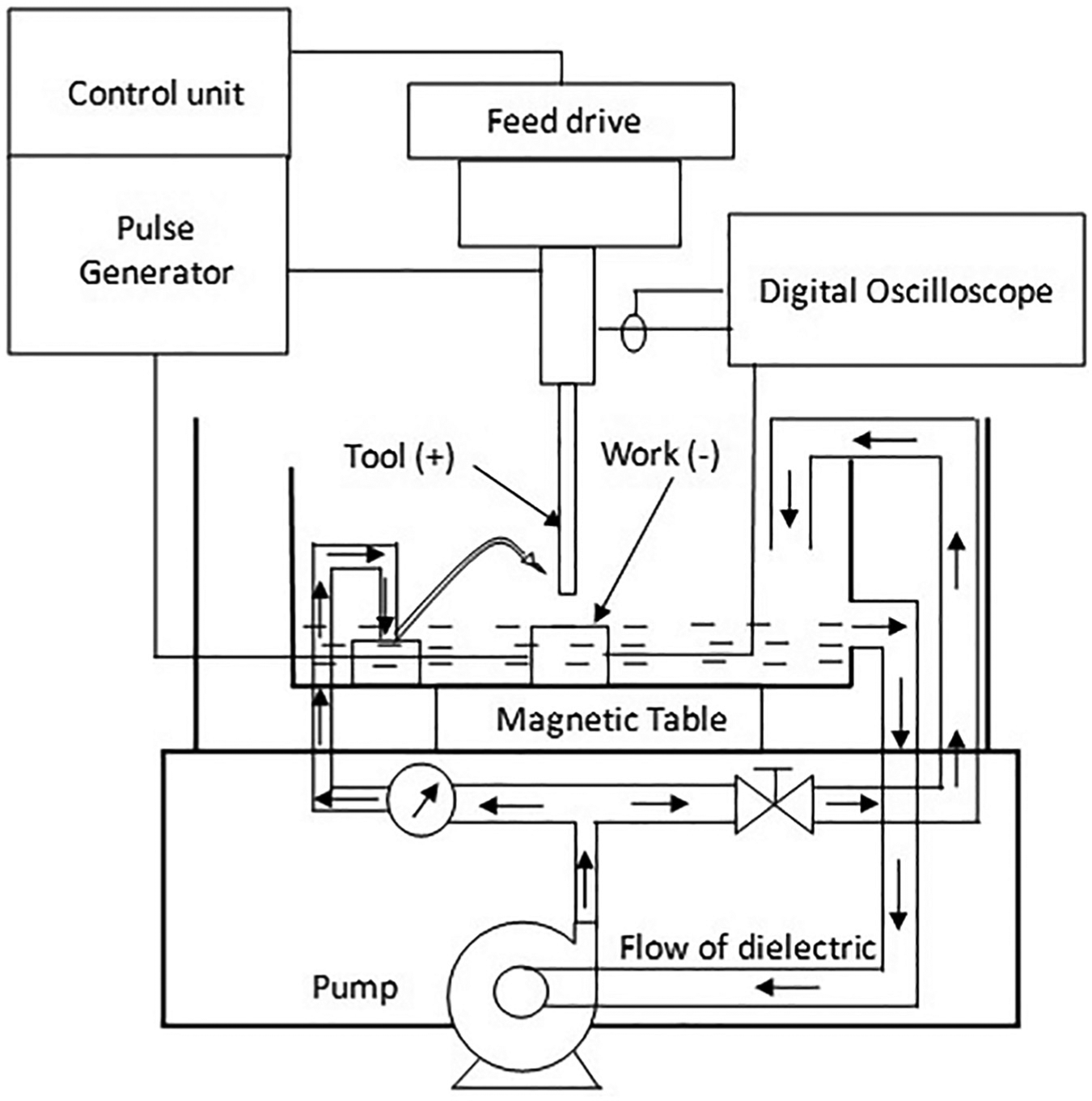
Experimental setup for powder-mixed EDM experiments.
In the present work, rough EDM with ultrasonic assistance is carried out using an agitator tub of 3.5 l capacity procured from Labline (India). The agitator tub is kept on the magnetic bed of the main container of the EDM machine. The complete experimental setup with agitator tub is schematically shown in Figure 3. In the experiments reported in the literature, the frequency is taken as 20 or 40 kHz, while the amplitude varies from 6 to 15 µm. 30 In the present work, 120 W agitator which works at a frequency of 30 kHz and 12 µm amplitude in horizontal direction is selected. Frequency and amplitude are not varied, as present work aims at studying the pulse characteristics with the superimposition of ultrasonic vibration. The pump available with the main EDM machine is used to supply the dielectric at a pressure of 0.7 kgf/cm2 into the electrode gap. The drain valve near the bottom of the tub allows the dielectric in the tub to flow into the main container of the EDM machine from where it reaches the main tank of the machine.
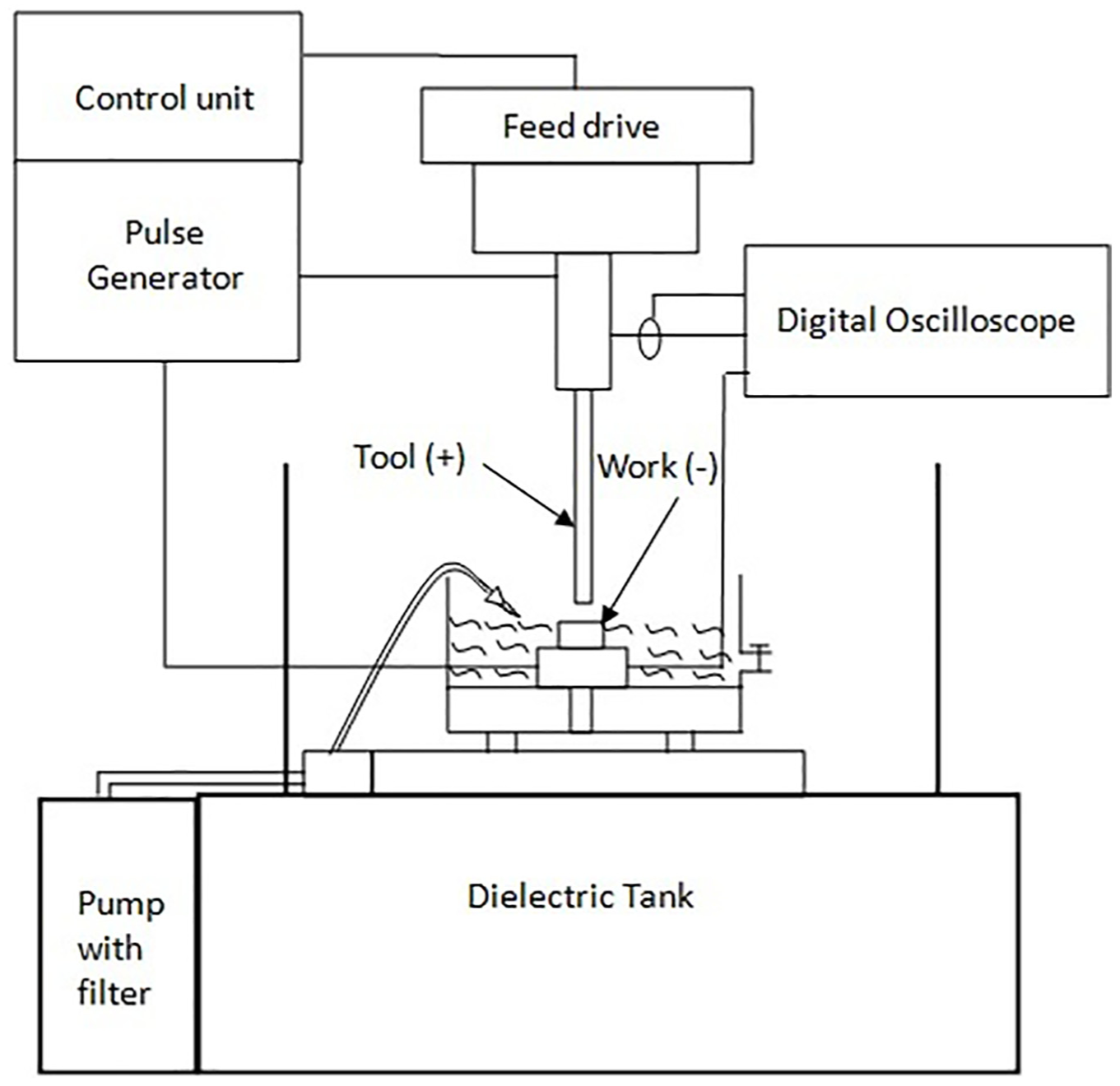
Experimental setup for ultrasonic-assisted EDM experiments.
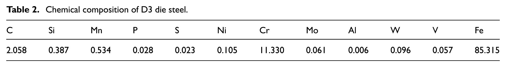
Work material is taken as D3 die steel whose chemical composition is given in Table 2. The work material is cut into samples having dimensions of 20 mm × 20 mm × 20 mm in annealed condition. The samples are then heated to reach a temperature of 1000°C in steps of 100°C after 10 h. A salt water bath is used to quench the samples for 14 h duration. The final hardness of samples achieved is approximately 55–58 HRC. A surface grinder is used to fine grind all the six faces of all the samples. A copper tool of circular cross section with diameter of 10 mm is used. A digital storage oscilloscope (DSO; DSOX2002A; Agilent, USA) with two channels and 1 GSPS speed is used to capture the voltage and current pulses. A voltage probe is available with the DSO itself. Hall effect–based current probe (model E3N; Chauvin Arnoux, France) is used for capturing current pulses. The polarity of tool is maintained as positive, with work material as negative for all the experiments.
Chemical composition of D3 die steel.
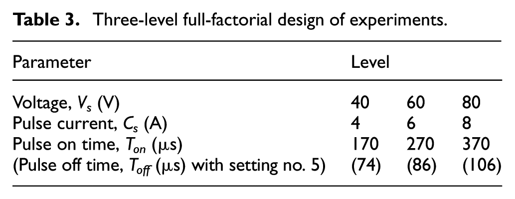
From an elaborate set of 125 experiments carried out in conventional EDM with five levels of process parameters, namely, voltage, current and pulse on time, rough machining regime is identified. The details are already reported in a paper communicated to a different journal. 11 In the present work, die-sinking experiments are conducted in the roughing regime with three levels of voltage Vs, current Cs and pulse on time Ton as given in Table 3, with powder-mixed dielectric and ultrasonic vibration. Each experiment is conducted for 5 min. In all the experiments, the weight of the sample before and after machining is measured using a weighing balance having resolution of 0.001 g. The change in weight over a machining duration of 5 min is used to calculate MRR.
Three-level full-factorial design of experiments.
Pulse shapes and characteristics
Pulse shapes in trains acquired for different EDM conditions are studied first and their characteristics are extracted for further analysis. Typical voltage and current pulse trains acquired during rough EDM with graphite powder-mixed dielectric and ultrasonic assistance are shown in Figure 4(a) and (b), respectively. For comparison, pulse trains obtained for the same conditions in conventional EDM are included as shown in Figure 4(c). The pulse shapes of each train show distinct differences. In order to have a quantitative assessment, pulse characteristics are captured by a novel thresholding approach in the present work. Figure 5 shows schematically the proposed thresholding approach, while Figure 6 gives the algorithm details in the form of flow diagram. Two threshold values, VL and VH, are used for the measured voltage signal. Rising portion of the voltage is identified by positive slope condition using Vi < Vi+1 and both crossing points L1 and H1 are located on it. After the dielectric breakdown, the voltage falls and this portion is identified by negative slope as Vi > Vi+1 and crossing point H2 on it. Maximum voltage Vb occurring between H1 and H2 is identified as breakdown voltage. Time interval between H2 and H1 is taken as ignition delay ti and H2 and L2 as discharge duration td. After the discharge, the voltage again falls and L2 is located on the falling portion. The average discharge voltage Vd between H2 and L2 is also identified leaving sufficient margin at both ends. On the current signal, crossing points C1 and C2 are located using a threshold value CT and average discharge current Cd is also identified as shown Figure 5. The discharge duration is taken as the average of duration computed from H2 and L2 on voltage signal and that from C1 and C2 on current signal. The dashed lines constructed based on the selected points and the values identified are taken to represent the hypothetical shapes of voltage and current pulses. The hypothetical pulses provide a basis for the classification of pulses as shown in Figure 7. In the present work, five types of pulses, namely, effective spark, weak spark, arc, short circuit and open circuit pulses, are considered adequate. The conditions for identifying these pulses are also included in the same figure. Code is written in MATLAB to implement the procedure outlined above. 32 Given the threshold values, the voltage and current signals are scanned automatically to determine breakdown voltage, ignition delay, discharge voltage, discharge current and discharge duration along with pulse types. Specific rules are also included to identify special situations such as overlapping or missing pulses.
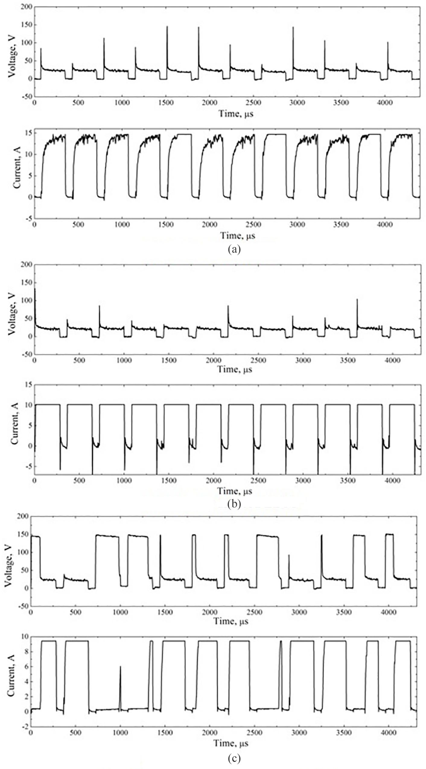
Typical pulse trains for rough EDM (experiment 8: Vs = 40 V, Cs = 8 A, Ton = 270 μs, fp = 2.81 kHz): (a) powder-mixed EDM, (b) ultrasonic-assisted EDM and (c) conventional EDM. 11
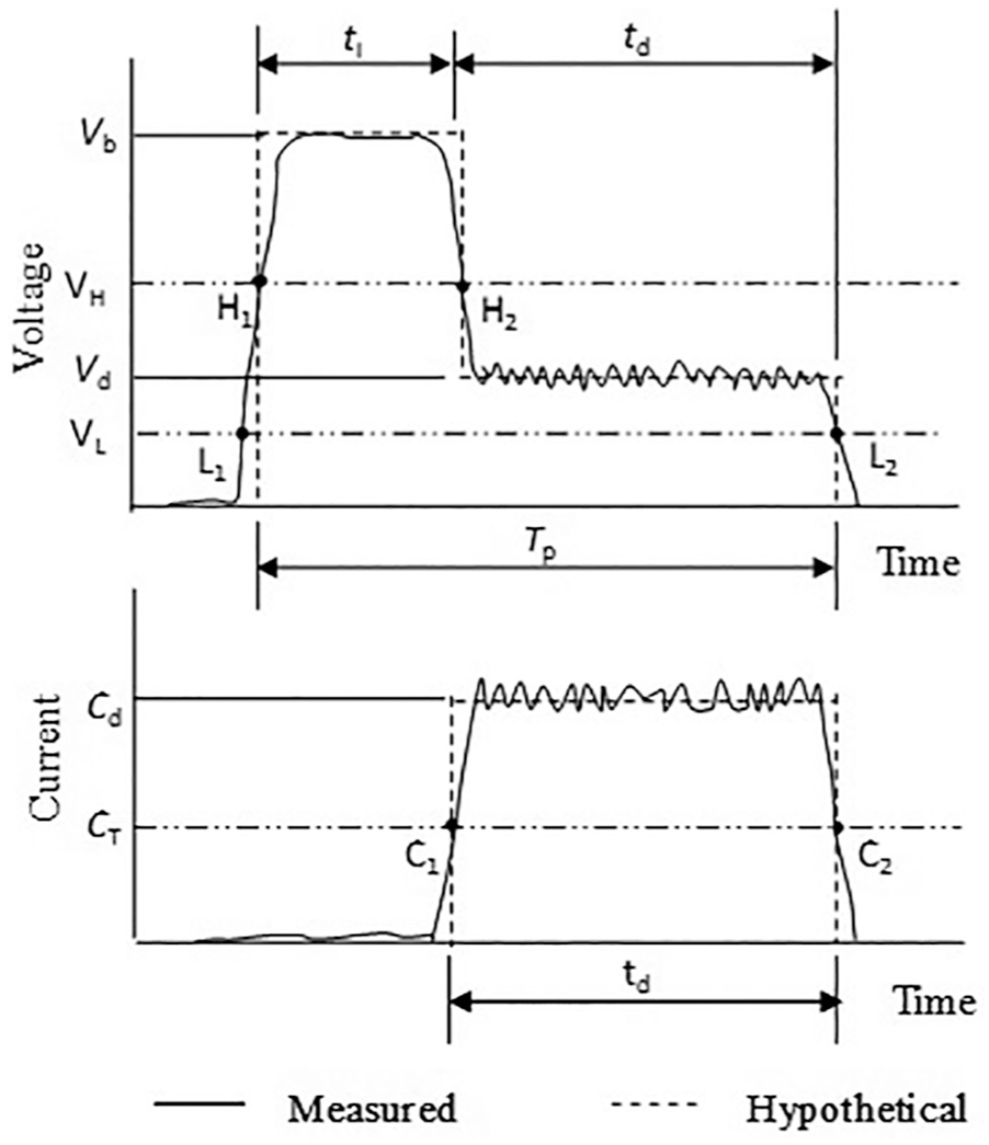
Thresholding of measured pulse trains and hypothetical pulse shapes.
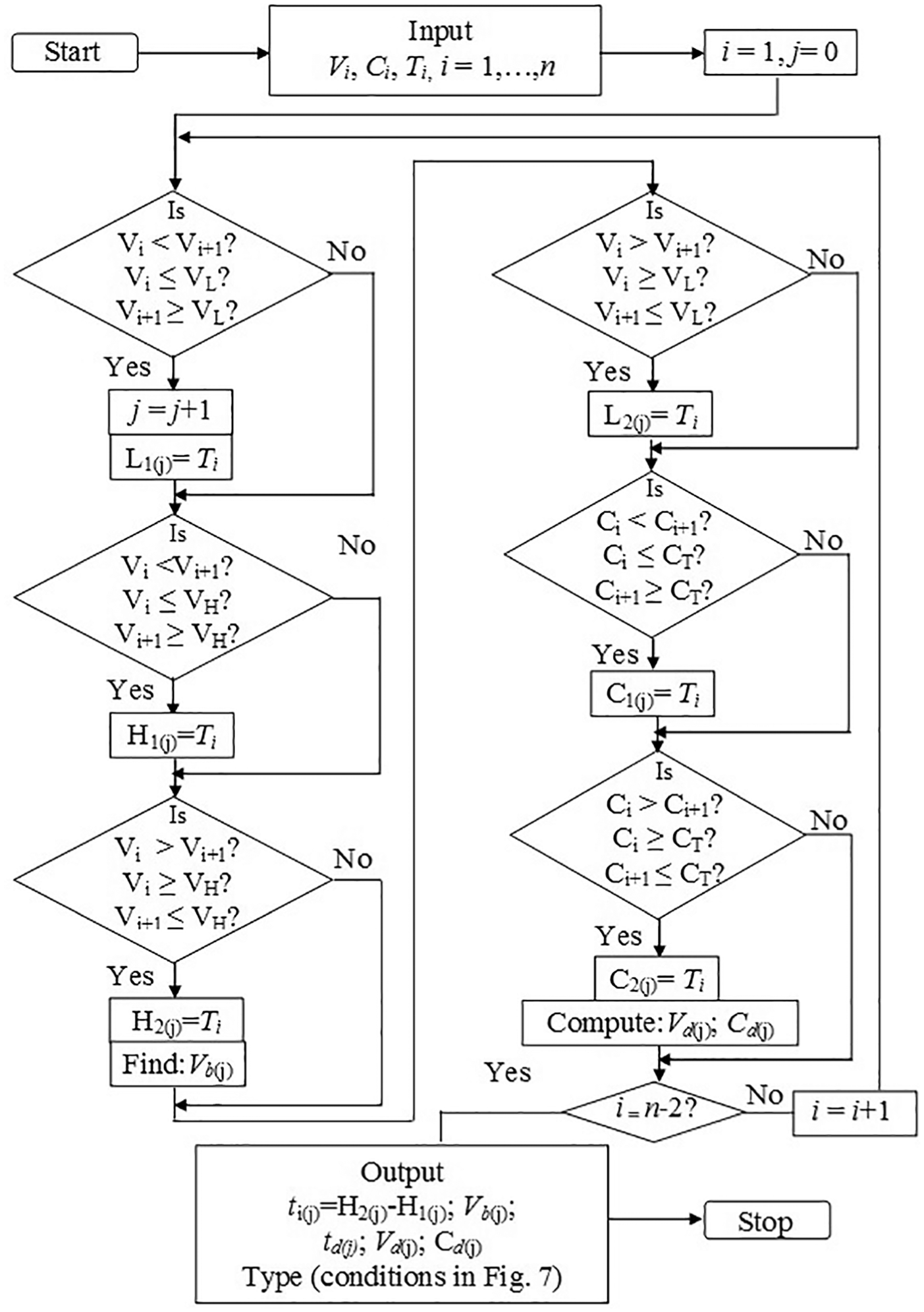
Flow diagram for the proposed thresholding approach.
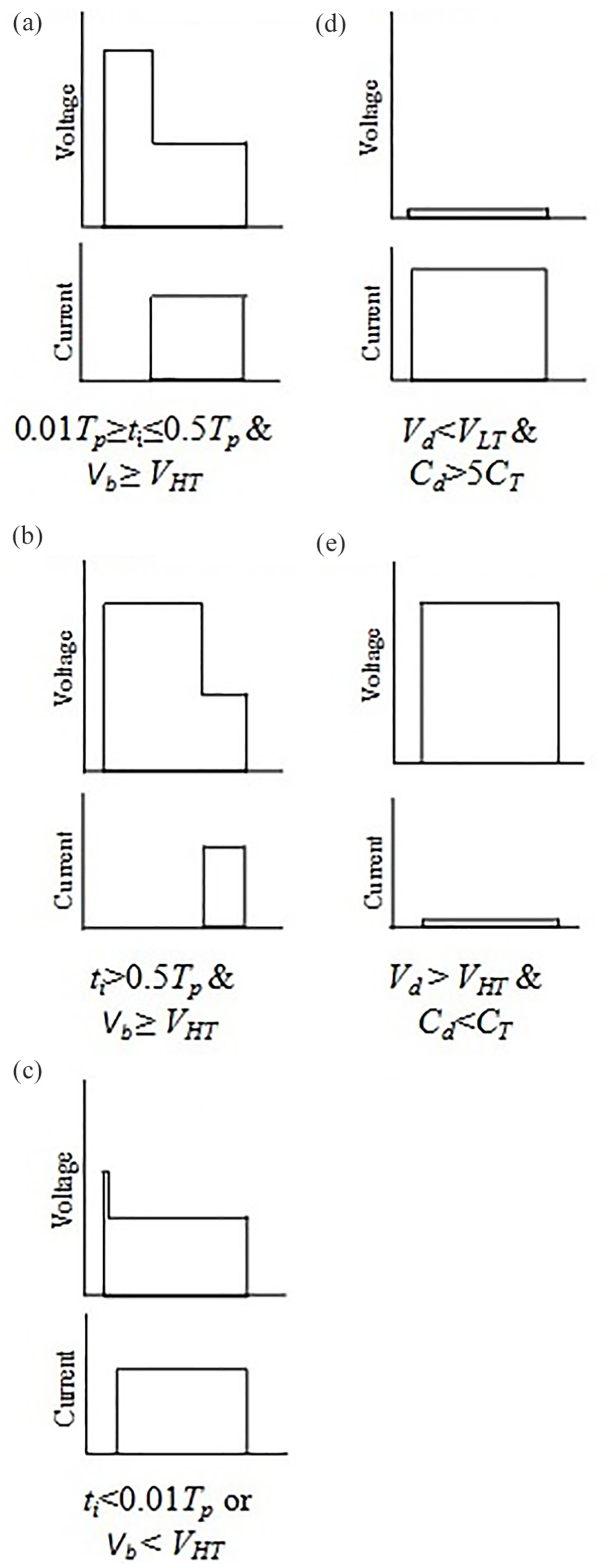
Pulse types and characteristics: (a) effective spark (ES), (b) weak spark (WS), (c) arc (A), (d) short circuit (S) and (e) open circuit (O).
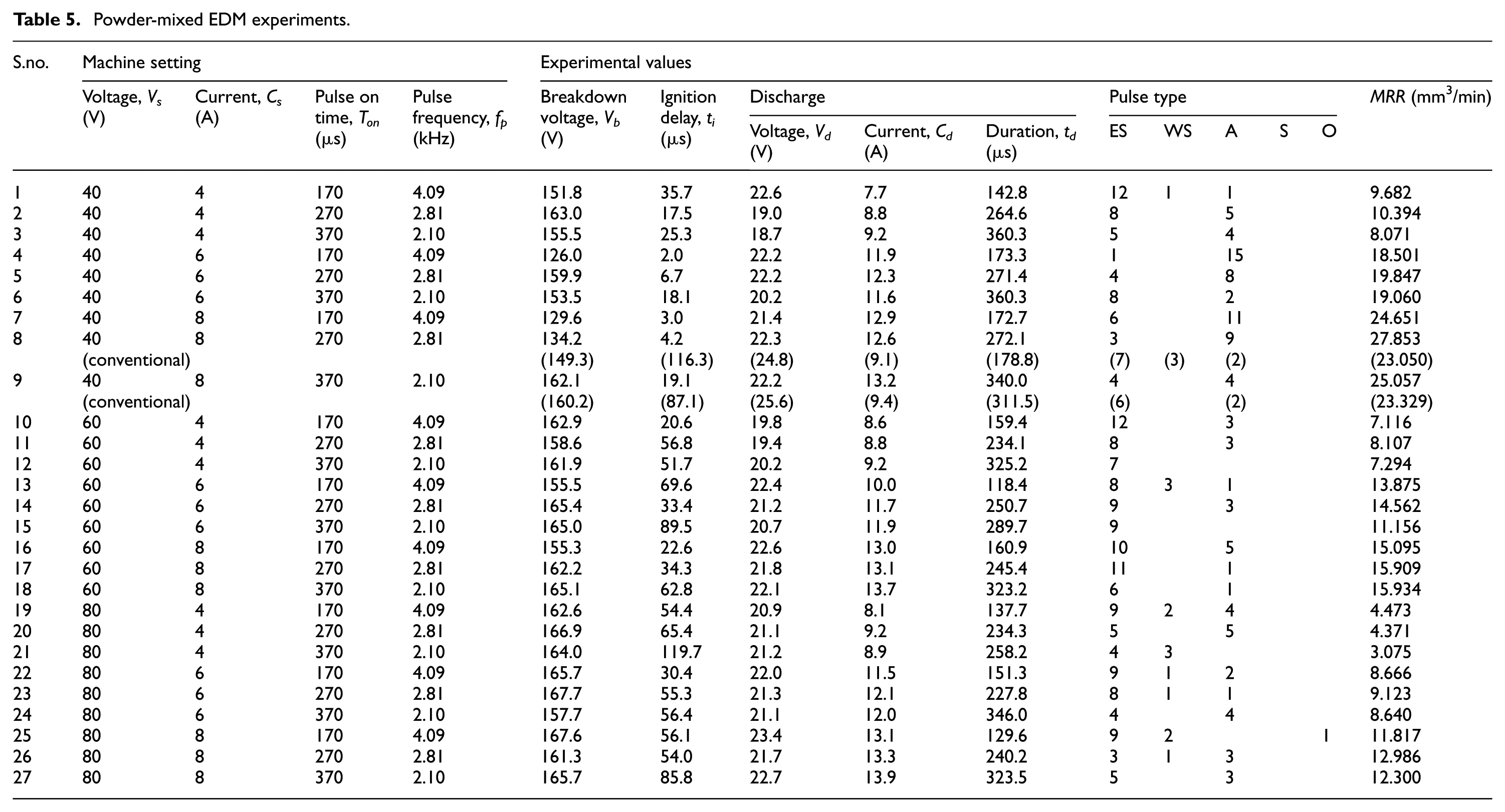
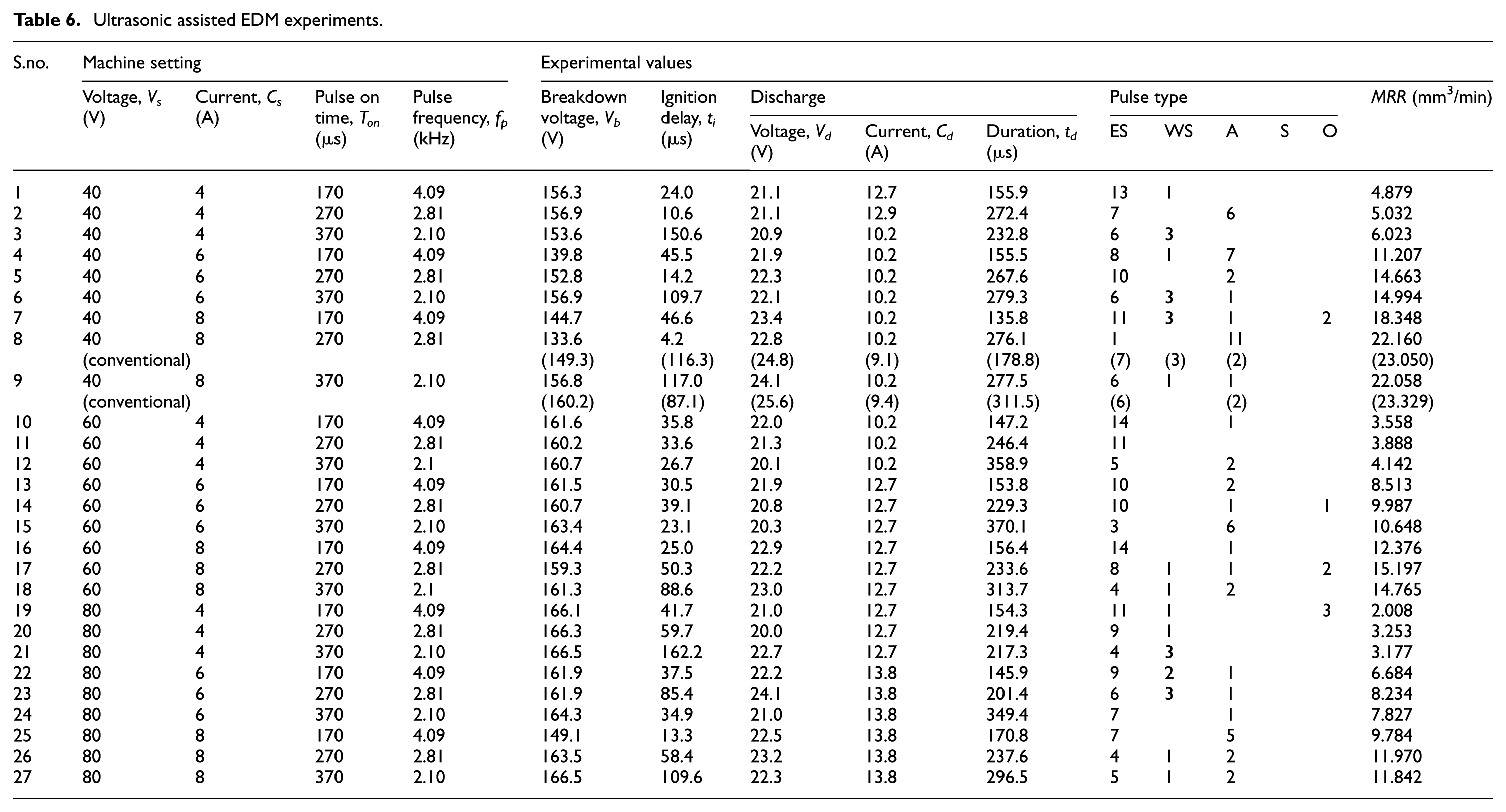
Table 4 gives the characteristics of the pulses for the typical pulses shown in Figure 4(a) and (b). The table also includes the pulse types for the pulse trains. Tables 5 and 6 give the machine settings in second to fifth columns, followed by pulse characteristics in other columns and MRR in the last column for the die-sinking with powder-mixed dielectric and ultrasonic-assisted EDM, respectively. The values obtained in conventional rough EDM are included within parentheses for experiments 8 and 9 only, as the complete details are reported in a previous paper. 11 For a meaningful comparison, Table 7 presents the minimum and maximum values for each of the characteristics considering the experimental region for conventional, powder-mixed and ultrasonic-assisted rough EDM individually.
Characteristics of typical pulse trains in Figure 4 (experiment 8: Vs = 40 V, Cs = 8 A, Ton = 270 μs, fp = 2.81 kHz).
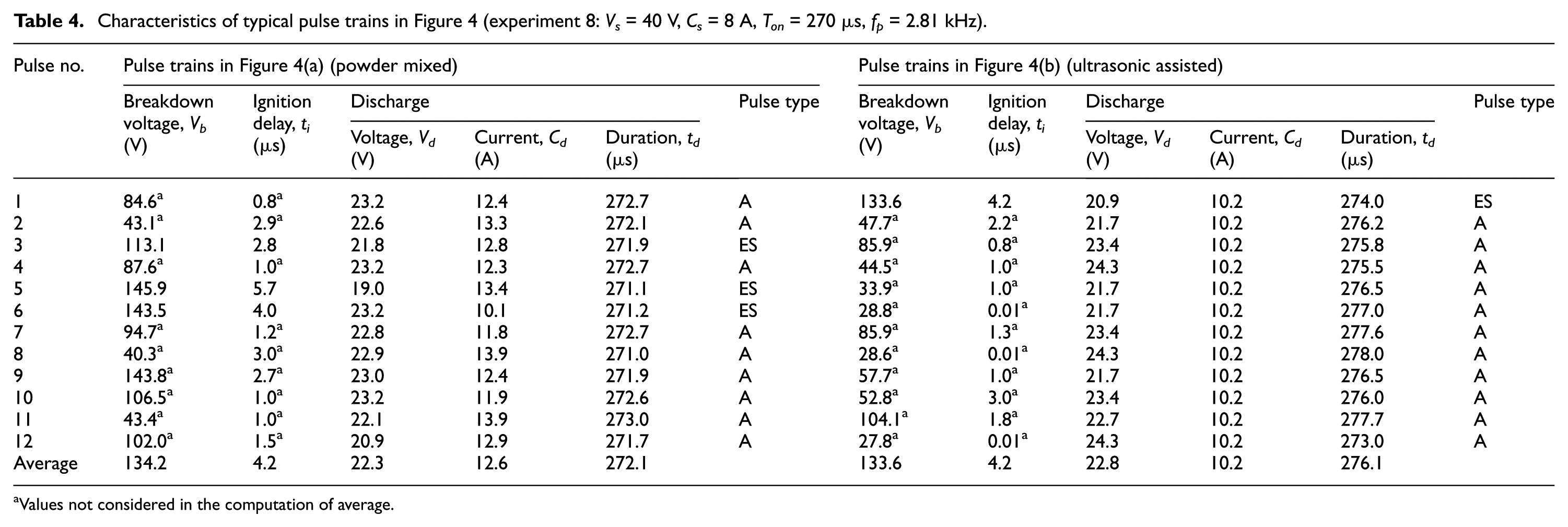
Values not considered in the computation of average.
Powder-mixed EDM experiments.
Ultrasonic assisted EDM experiments
Variation of buildup and discharge parameters in the experimental region.
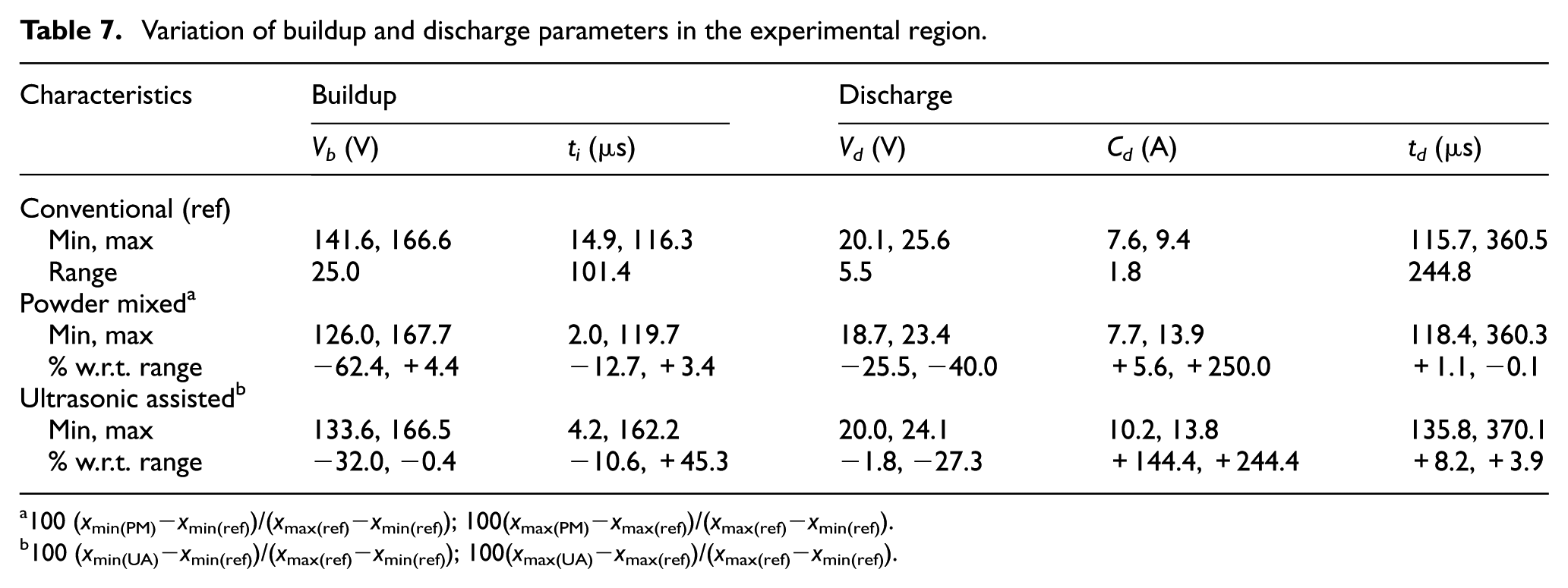
100 (xmin(PM)−xmin(ref))/(xmax(ref)−xmin(ref)); 100(xmax(PM)−xmax(ref))/(xmax(ref)−xmin(ref)).
100 (xmin(UA)−xmin(ref))/(xmax(ref)−xmin(ref)); 100(xmax(UA)−xmax(ref))/(xmax(ref)−xmin(ref)).
Two new parameters defined in the previous work 11 for analyzing the rough and finish die-sinking are considered in the present work also. Since these are based on phenomenological reasoning, they are helpful in studying the changes in the gap phenomena with powder addition and ultrasonic assistance.
First parameter is defined based on pulse energy (Ep) which is obtained by multiplying average discharge voltage, discharge current and discharge duration as given in equation (1)

Using the above pulse energy (Ep) in equation (1), the energy expended over a second (E) is determined from equation (2)
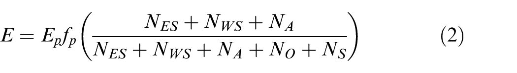
where fp is the pulse frequency, and NES, NWS, NA, NO and NS are the number of effective spark, weak spark, arc, open and short circuit pulses, respectively.
The second parameter termed as performance factor (PF) is defined in equation (3)
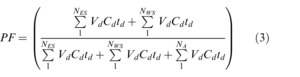
This parameter PF identifies the condition that promotes sparking, as higher values show higher energy associated with effective as well as weak sparks in relation to the total discharge energy.
Figures 8 and 9 show variations of MRR, E and PF in rough die-sinking EDM for powder-mixed and ultrasonic-assisted conditions, respectively. Table 8 gives a comparison of MRR, E and PF with conventional EDM for the selected experiments. Cross-sectional images of the workpieces obtained using optical microscope are also shown in Figure 10 for the typical parameters chosen (experiment 8) in rough machining.
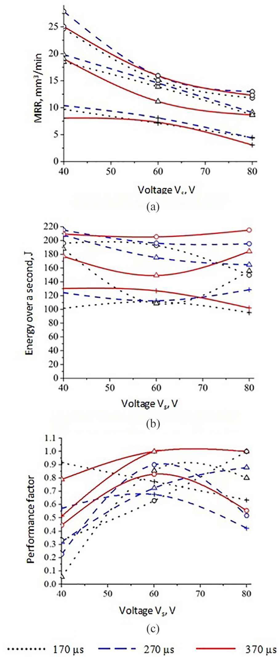
Powder-mixed rough EDM (+, 4 A; Δ, 6 A; o, 8 A): (a) material removal rate (MRR), (b) energy expended over a second (E) and (c) performance factor (PF).
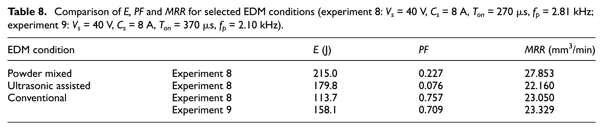
Comparison of E, PF and MRR for selected EDM conditions (experiment 8: Vs = 40 V, Cs = 8 A, Ton = 270 μs, fp = 2.81 kHz; experiment 9: Vs = 40 V, Cs = 8 A, Ton = 370 μs, fp = 2.10 kHz).
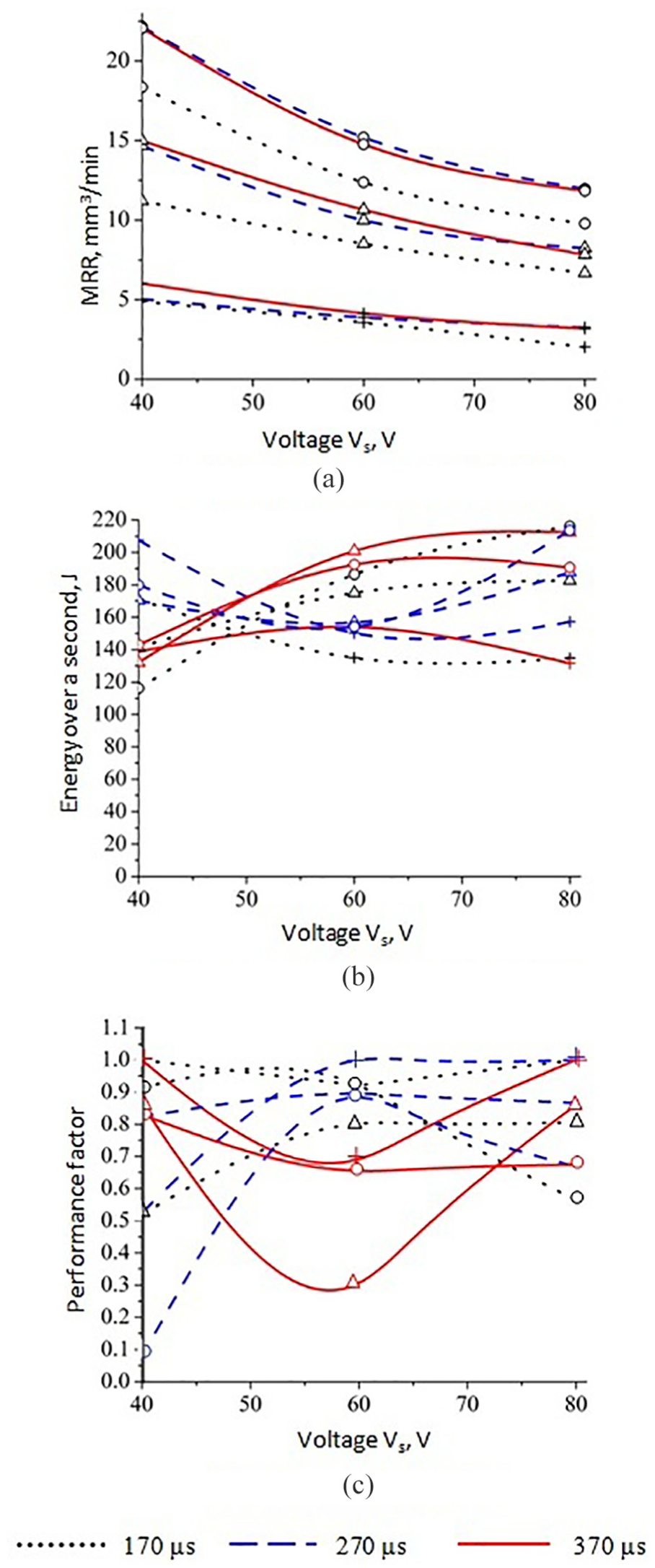
Ultrasonic-assisted rough EDM (+, 4 A; Δ, 6 A; o, 8 A): (a) material removal rate (MRR), (b) energy expended over a second (E) and (c) performance factor (PF).
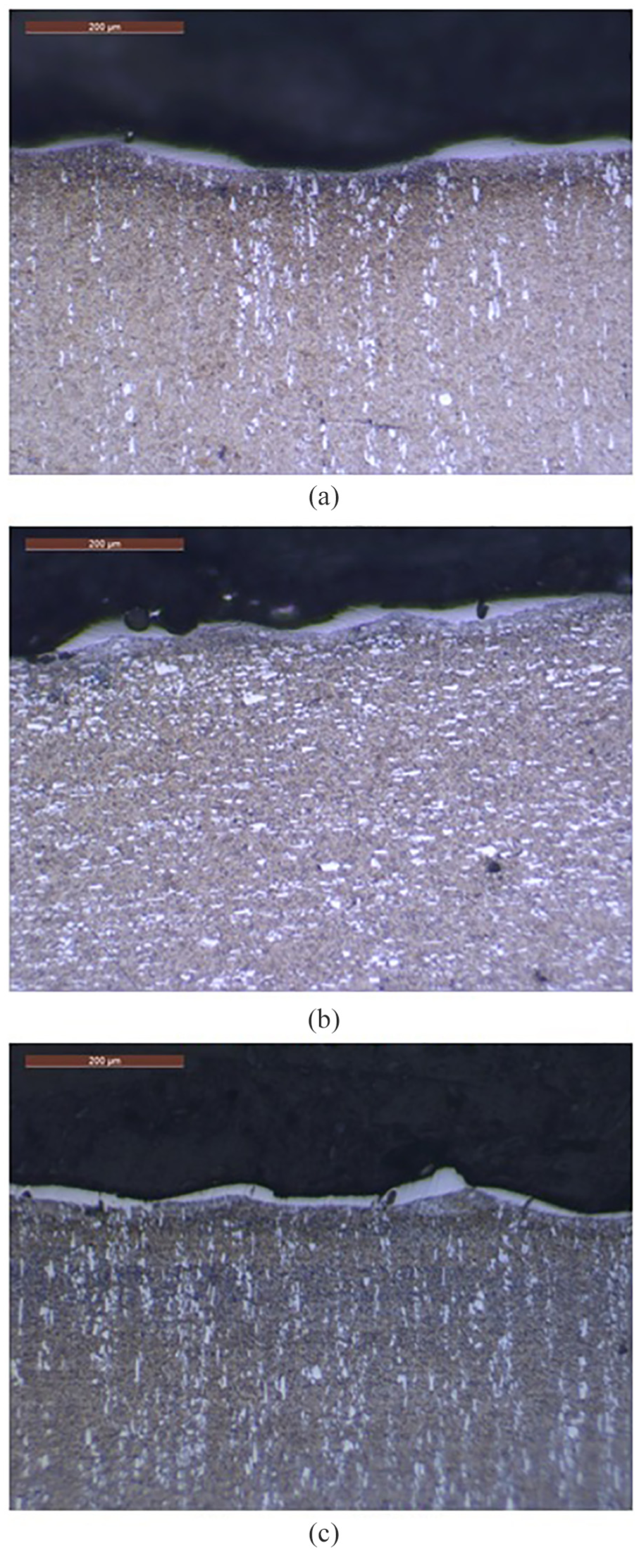
Cross-sectional images of rough EDM specimen obtained using optical microscope: (a) powder-mixed EDM, (b) ultrasonic-assisted EDM and (c) conventional EDM. 11
Results and discussions
MRR
The results presented in this work allow proper comparison, as conventional, powder-mixed and ultrasonic-assisted die-sinking EDM experiments are carried out on the same machine and work material. In the experimental region considered in the present investigation, MRR varies from 3.075 to 27.853 mm3/min in powder-mixed EDM and from 3.177 to 22.160 mm3/min in ultrasonic-assisted EDM, when compared with 2.795–23.329 mm3/min in conventional EDM. The influence of powder addition is seen to push the upper limit of MRR to higher values. Further analysis shows that, even though the MRR for experiment 9 (23.329 mm3/min) is slightly higher than that for experiment 8 (23.050 mm3/min) in conventional EDM, affected surface layer is more prominent in experiment 9 than in experiment 8 as reported in an earlier paper. 11 In the powder-mixed EDM, maximum MRR of 27.853 mm3/min is obtained for experiment 8, but the MRR obtained with experiment 9 is lower (25.057 mm3/min). Therefore, setting conditions corresponding to experiment 8 are chosen for comparison of all the three EDM processes.
The results in Tables 5 and 6 show that the conditions in experiment 8 favor maximum MRR in powder-mixed (27.853 mm3/min) and ultrasonic-assisted (22.160 mm3/min) EDM. It is a surprise finding, as the authors expected MRR to reach maximum values at different parameter combinations. With reference to conventional EDM, the powder-mixed EDM gives rise to 20.8% increase in MRR, but there is a marginal reduction of 3.9% with the ultrasonic-assisted EDM in experiment 8. In conventional EDM, when the voltage between the electrodes reaches a breakdown value, the dielectric breaks down due to ionization. An avalanche of ions and electrons is released during the ionization and a plasma channel is formed between the electrode surfaces. The discharge starts with the flow of current in the plasma channel and the temperature inside plasma reaches a very high value. This high-temperature plasma causes local heating and melting of the electrode surface. When the plasma channel collapses at the end of the pulse duration, a part of the molten metal solidifies on the surface as a white layer. The remaining part gets ejected from the electrode gap as debris due to the pressure created by the collapse of plasma channel. The fine debris particles which are still present in the dielectric act as secondary sites and provide condition favorable for discharges.
When graphite powder is added to the dielectric medium, they also act as potential sites for discharges. Zhao et al. 13 have explained that series of discharges occur at these sites and stream of ions and electrons gets liberated. The energy associated with the plasma channel increases considerably. It is reported that series of discharges at these sites result in the enlargement of discharge gap and widening of discharge passage. In the present work, authors refer to the spots at which graphite powder remain suspended in the dielectric medium as nucleation sites as these are intentionally introduced in the electrode gap. The increase in energy in the plasma channel with graphite powder is responsible for higher MRR.
The reduction in MRR with ultrasonic vibration can be attributed to the cleaning effect of ultrasonic vibration which removes the debris from the gap. Kremer et al. 27 also observed that the effect of ultrasonic vibration on MRR is very minimal in roughing condition. This effect is evident to some extent, as the MRR drops down marginally from that obtained in conventional EDM. As the powder mix and ultrasonic assistance have opposite effect on MRR, the authors have decided not to conduct experiments by combining these two. Further investigation by changing the powder concentration and ultrasonic amplitude/frequency may throw more light on the process changes. However, the scope of the present work limits the investigation to bringing out the changes in the gap phenomena of these EDM processes as reflected in the pulse trains.
Pulse trains
The gap phenomenon in EDM is a stochastic process and researchers have attempted to model the same for control purposes. 9 The pulse train is considered as a stationary process which implies that the statistical properties of signal obtained remain unchanged over a considerable time period. 33 Therefore, this property of the signals acquired within the experimental duration allows pulse train analysis without any need for repeating the experiments. Furthermore, it permits the readers to follow every step and the intermediate result reported in the present work. After examining all the pulse trains obtained in the present investigation, the lower and higher threshold values for the voltage are fixed as 11 and 75 V, respectively, and the threshold for current is fixed as 3 A. In order to capture the pulses having shorter breakdown voltage, the program is re-run with 45 V as higher threshold value.
Study of the pulse trains shown in Figure 4(a) and the characteristics listed in Table 4 reveal that three effective sparks are present while remaining nine are arcs. In comparison with conventional EDM, there is an increase in number of arcs from two to nine (experiment 8). From Figure 4(b) and Table 4, it can be seen that the number of arcs has increased to 11 from 2 with ultrasonic vibration in the conventional EDM (experiment 8). Table 6 shows that maximum ignition delay for ultrasonic-assisted EDM is 162.2 μs which is about 36.0% more than that obtained with powder-mixed EDM (Table 5). Such a delay in the breakdown can be expected as ultrasonic vibration keeps the gap cleaner to some extent by removing the debris. However, there is a slight reduction in MRR in comparison with 23.050 mm3/min (experiment 8) obtained in conventional mode. Still, the MRR of 22.160 mm3/min is the maximum for experiment 8 among the values obtained with ultrasonic assistance.
Figure 10 shows the cross-sectional images of the workpieces machined by all three EDM processes in experiment 8. As the number of arcs increases, thickness of the white layer representing recast and heat-affected zone increases. It may be noted that the layer is thinner and somewhat uniform with powder-mixed EDM, while ultrasonic-assisted EDM shows thicker layer and erratic nature of the process with increased number of arcs. Increased number of arcs with ultrasonic vibration may appear to be in contradiction with its cleaning action. It is important to note that contamination in the gap together with the closeness of surface peaks influence the arcing phenomenon. The ultrasonic vibration used in the present work though cleans the gap to some extent, the surface peaks are brought closer favoring the arcing phenomenon.
Pulse characteristics
It is seen from Tables 5 and 6 that breakdown voltage, ignition delay, discharge voltage, discharge current and discharge duration for powder-mixed and ultrasonic-assisted EDM vary in relation to each other. In Table 7, apart from the minimum and maximum values, the percentage variation of each characteristic in relation to that of conventional EDM is also included. In the formulae given as footnotes below the table, the range of the characteristic for the conventional EDM is taken as the basis for computation. It may be seen that maximum breakdown voltage does not vary much with reference to that of conventional EDM, as it is just 4.4% higher for powder-mixed EDM and 0.4% lower for ultrasonic-assisted EDM. However, powder addition lowers the minimum breakdown voltage by nearly 60% which is almost twice that of ultrasonic effect. The reason could be the nucleation sites that facilitate the discharge phenomenon. However, the ultrasonic vibration prolongs the maximum ignition delay by about 45%. The debris in the electrode gap is cleared effectively with the ultrasonic assistance and hence the ignition is delayed substantially. The range of discharge voltages is quite small (5.5 V), but the powder addition reduces the maximum discharge voltage by 40% when compared to 27% with ultrasonic assistance within this range. Both powder addition and ultrasonic assistance increase the maximum discharge current considerably by the same level. However, the maximum discharge duration fairly remains the same. It must be remembered that the effective and weak sparks only give rise to breakdown voltage and ignition delay, whereas these sparks along with arcs contribute to discharge parameters. Also, the number of sparks and arcs vary with different conditions. Therefore, it becomes necessary to consider the type of pulses and associated energies while analyzing the MRR.
Proposed parameters and MRR
In case of powder-mixed EDM, MRR in Figure 8(a) shows a general trend of reduction with increase in voltage. However, a pulse on time of 270 μs favors higher MRR. Figure 9(a) for ultrasonic-assisted EDM also shows a downward trend in MRR with increase in voltage as observed with powder-mixed EDM. With the same pulse on time of 270 μs, a higher MRR of 22.160 mm3/min is obtained for 40 V and 8 A.
The two new parameters, namely, energy expended over a second (E) and PF, defined in the present research work are able to differentiate between the MRRs for different setting parameters. In terms of energy expended over a second, maximum value is observed for 40 V and 270 μs (Figure 8(b)). The corresponding PF (Figure 8(c)) is 0.227 showing that the share of spark discharges is less. This is much lesser than 0.757 observed for conventional EDM (Table 8). The discharge phenomenon in the gap adjusts itself to increase the energy expended over a second to 215.0 J from 113.7 J. It is possible to select conditions such as 60 V, 6 A and 370 μs for which PF is 1, but the MRR is only 11.156 mm3/min as E reduces to 149.2 J.
From the plot of two new parameters for ultrasonic-assisted EDM, the maximum value of energy expended over a second is observed for 40 V and 270 μs (Figure 9(b)). The PF is 0.076 showing that the share of spark discharges is much less. This is lower than 0.227 observed for powder-mixed EDM (Table 8). The discharge phenomenon in the gap adjusts itself to decrease the energy expended over a second to 179.8 J from 215.0 J. From Figure 9(c), it is seen that a PF of 1 can be realized when the voltage is 40, current is 4 A and pulse on time is 370 μs. However, E is reduced to 138.8 J and MRR is drastically reduced to 6.023 mm3/min.
Conclusion
This article presents a comprehensive study on the material removal performance of powder-mixed and ultrasonic-assisted die-sinking EDM on the basis of pulse train analysis.
The thresholding approach captures important characteristics of the pulses. Based on the pulse characteristics, the pulse shapes are identified as effective spark, weak spark, arc, short and open circuit pulses. Proportion of the arcs, in relation to the sparks in the conventional EDM, increases when the powder is added to the dielectric medium. Higher proportion of arcs appears when the ultrasonic vibration is used.
Energy associated with sparks and arcs over a second (E) is responsible for the material removal, while the PF shows the contributions from the spark pulses. The EDM processes adjust the energy expended over a second, with PF getting altered.
The results obtained show an enhancement of 20.8% in MRR with E of 215 J and PF of 0.227 using powder-mixed dielectric in relation to the conventional EDM, as the powder in the dielectric provides nucleation sites for series of discharges within the gap. In ultrasonic-assisted EDM, there is a marginal reduction of 3.9% in MRR with E of 179.8 J and PF of 0.076. This is due to the fact that ultrasonic vibration clears the debris from the gap.
The present approach can be extended to study the effect of different powder types, powder sizes and concentration, as well as ultrasonic vibration of different frequency and amplitudes, and identify conditions for maximizing MRR.
Footnotes
Appendix 1
Declaration of conflicting interests
The author(s) declared no potential conflicts of interest with respect to the research, authorship and/or publication of this article.
Funding
The author(s) disclosed receipt of the following financial support for the research, authorship, and/or publication of this article: The authors are thankful to DST (grant no. SR/S3/MERC-68/2004, dated 08-06-2007) and IIT Madras (grant no. MEE/03-04/181/IDRP/OVKC, dated 01-10-2003) for providing the measurement facilities, at the Manufacturing Engineering Section, necessary to carry out the present investigation.