
Abstract
Tool coatings can improve the machinability performance of difficult-to-cut materials such as titanium alloys. Therefore, in the current work, high-speed milling of Ti6Al4V titanium alloy was carried out to determine the performance of various coated cutting tools. Five types of coated carbide inserts – monolayer TiCN, AlTiN, TiAlN and two layers TiCN + TiN and AlTiN + TiN, which were deposited by physical vapour deposition – were employed in the experiments. Tool wear, cutting force, surface roughness and chip morphology were evaluated and compared for different coated tools. To understand the tool wear modes and mechanisms, detailed scanning electron microscope analysis combined with energy dispersive X-ray of the worn inserts were conducted. Abrasion, adhesion, chipping and mechanical crack on flank face and coating delamination, adhesion and crater wear on rake face were observed during high-speed milling of Ti6Al4V titanium alloy. In terms of tool wear, the lowest value was obtained with TiCN-coated insert. It was also found that at the beginning of the machining pass TiAlN-coated insert and at the end of machining TiCN-coated insert gave the lowest cutting force and surface roughness values. No change in chip morphology was observed with different coated inserts.
Introduction
Titanium and its alloys have good mechanical properties, high strength-to-weight ratios and high corrosion resistance; therefore, they are utilized extensively in medical, aerospace, automotive, 1 petroleum and chemical industries. 2 Yet, machinability of these alloys is poor owing to some properties such as low thermal conductivity leading to high cutting temperatures and high chemical reactivity. 3 Properties of these alloys can cause high cutting temperature in the cutting region and strong bond and adhesion between the cutting tool and workpiece material. Thus, tool wear is rapid during machining of titanium alloys. 4 Therefore, attempts should be conducted to diminish the negative effects of titanium alloys during machining.
Nowadays, the use of Ti6Al4V titanium alloy is increasing in machining area, which creates new difficulties in machining operations and requires high-performance cutting tools. Therefore, efforts have been focused on different tool coating materials in recent years. It is known that coated tools reduce cutting temperature and forces, increase wear resistance and improve surface-related properties. Coated tools can also act as a diffusion barrier, which induces the reduction in the tool temperature and temperature-related tool wear. 5 Jawaid et al. 6 investigated the cutting performance of physical vapour deposition (PVD)-TiN and chemical vapour deposition (CVD)-TiCN/Al2O3-coated carbide tools during face milling of Ti6Al4V alloy by evaluating the tool life and tool wear mechanisms. They found that CVD-coated tools showed better performance than PVD-coated tools when evaluating tool life. These researchers also explained that excessive chipping and flaking were the dominant tool failure mechanisms during milling of Ti6Al4V alloy. 6 Some researchers employed uncoated and multilayer CVD-coated carbide tools in milling of Ti-6242S material.7,8 Nouari and Ginting 7 stated that localized flank wear and adhesion wear were the dominant wear modes in milling of Ti-6242S alloy. Plastic deformation, flaking, cracking, chipping and fracturing were the other tool failure mechanisms during milling of this material. 8 Niu et al.9,10 compared the performance of PVD-TiN/TiAlN and CVD-TiN/Al2O3/TiCN carbide inserts during face milling of TC6, TC11 and TC17 titanium alloys. These researchers said that PVD-TiN/TiAlN-coated insert was more suitable than CVD-TiN/Al2O3/TiCN in milling of TC6 alloy and main wear mechanisms were found to be spalling and adhesion. 9 Niu et al. 10 found that PVD-TiN/TiAlN-coated insert was suitable for milling of TC17 alloy and CVD-TiN/Al2O3/TiCN was suitable for milling of TC11 alloy. Dominant tool failure modes for PVD-TiN/TiAlN-coated insert were crater wear and chipping during milling of TC11 and TC17 alloys. When CVD-TiN/Al2O3/TiCN was used, the main failure mode was flank wear for TC11 alloy and breakage and flaking were the main failure modes for TC17 alloy. It was found that adhesion and abrasion were the main wear mechanisms for both coated inserts during milling of TC11 alloy. For TC17 alloy, adhesion was the main wear mechanism. Cutting performance of the tools coated with PVD multilayer TiAlN and AlCrN coatings was evaluated during high-speed milling of Ti6Al4V alloy by Li et al. 11 It was concluded that TiAlN coatings gave higher wear resistance than AlCrN coatings. 11 Fox-Rabinovich et al. 12 found that AlTiN coating gave lower flank wear as compared to TiAlCrN coating during milling of Ti6Al4V alloy. Biksa et al. 13 stated that AlTiN-based multilayered coatings were better suited for machining of titanium alloys as compared with monolayered AlTiN.
From the literature review, it was seen that unfortunately limited study was published in the area of the performance of coated carbide inserts in high-speed milling of Ti6Al4V alloy. Further research about tool wear behaviour of the coated inserts, cutting force variation and surface quality in the milling of Ti6Al4V alloy was needed. This study presented the results of high-speed milling of Ti6Al4V titanium alloy with five kinds of coated tools. Inserts with different coating materials, namely, monolayer TiCN, AlTiN, TiAlN and two layers TiCN + TiN and AlTiN + TiN, which were deposited by PVD, were utilized in the experiments. Tool wear mechanisms, cutting forces, surface roughness and chip morphology were investigated.
Experimental method
High-speed milling tests were conducted in dry cutting conditions at DECKEL MAHO DMU 60 P five-axis computer numerical control (CNC) that can reach a maximum speed of 12,000 r/min. Experimental setup is given in Figure 1. As workpiece materials, Ti6Al4V titanium alloy with a hardness of 35 HRC was employed. Inserts (Figure 1) with different coating materials were selected as cutting tools. Five types of coated carbide inserts, namely, monolayer TiCN, TiAlN, AlTiN and two layers TiCN + TiN and AlTiN + TiN were used. All types of inserts had similar geometry and dimensions (ISO designation: APKT 1003PDR), only coating material was different. The insert was a rhombic shape with a nose radius of 0.8 mm. A tool holder fitted with two inserts was employed in the experiments and the diameter of the tool holder was 16 mm. The overhang length of cutting tool was 43 mm. Before conducting experiments, the static runout was measured with dial gauge at the shaft of tool holder and the values were found to be below 2 µm.
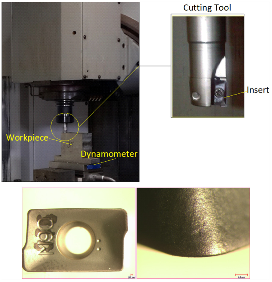
Experimental setup and geometry of insert.
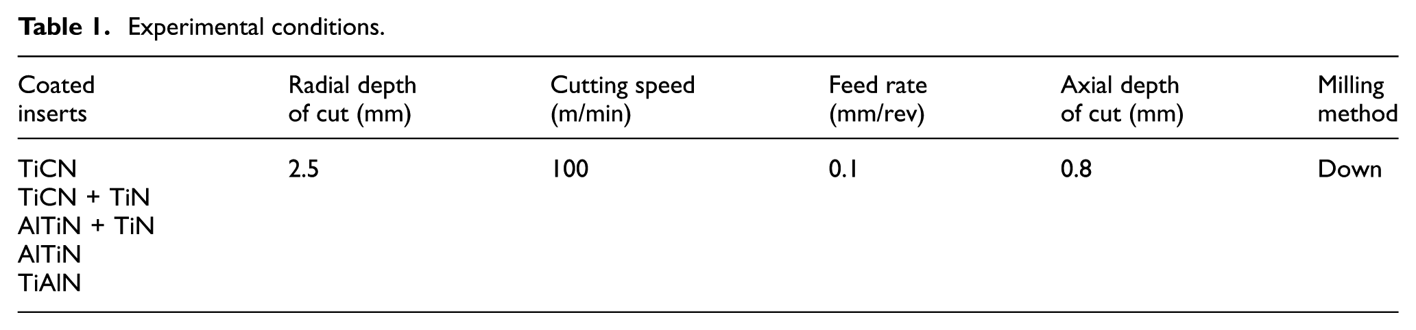
Experiments were carried out at constant conditions and experimental conditions are presented in Table 1.
Experimental conditions.
The tool wear for each coating material was monitored at periodic intervals (after machining of 1000 mm) to examine the progress of tool wear. In the experiments, after each pass, the machining process was interrupted, the inserts were removed from the tool holder and evaluated by employing a Nikon SMZ800 optical microscope before the next pass. After the wear measurement, the insert was again clamped into the tool holder for further experiment. These procedures were repeated when the machining length reached 3000 mm (at the end of third pass) and the milling process was ended owing to the restriction of workpiece material. When experiments were finished, the final form of inserts (at the end of third pass) was observed using a scanning electron microscope (SEM, Philips XL30). Flank and rake faces of the inserts were evaluated qualitatively and maximum wear on flank face was measured to compare the performance of coating materials quantitatively. Energy dispersive X-ray (EDX) spectroscopy was employed to determine elemental analysis of worn cutting inserts. For each machining pass and coated material, the chip samples were collected after machining process and the morphology of the chips was observed with the optical microscope. Cutting forces during high-speed milling were measured by means of piezoelectric dynamometer (Kistler, type 9257B) mounted under the workpiece. The charge occurred at the dynamometer was amplified by an 8-channel amplifier (type 5070A). The average value of nine peak-to-valley values of the forces was taken into consideration in the force analysis. In this study, average surface roughness (Ra) was selected as a roughness parameter. Surface roughness was measured along the feed direction via a Mitutoyo Surftest 301 profilometer. In surface roughness measurements, number of sampling and cut-off length were chosen as 5 and 0.8 mm, respectively. Six measurements at the different locations on workpiece surface were taken and the average of these values was considered as surface roughness value.
Results and discussion
Tool wear
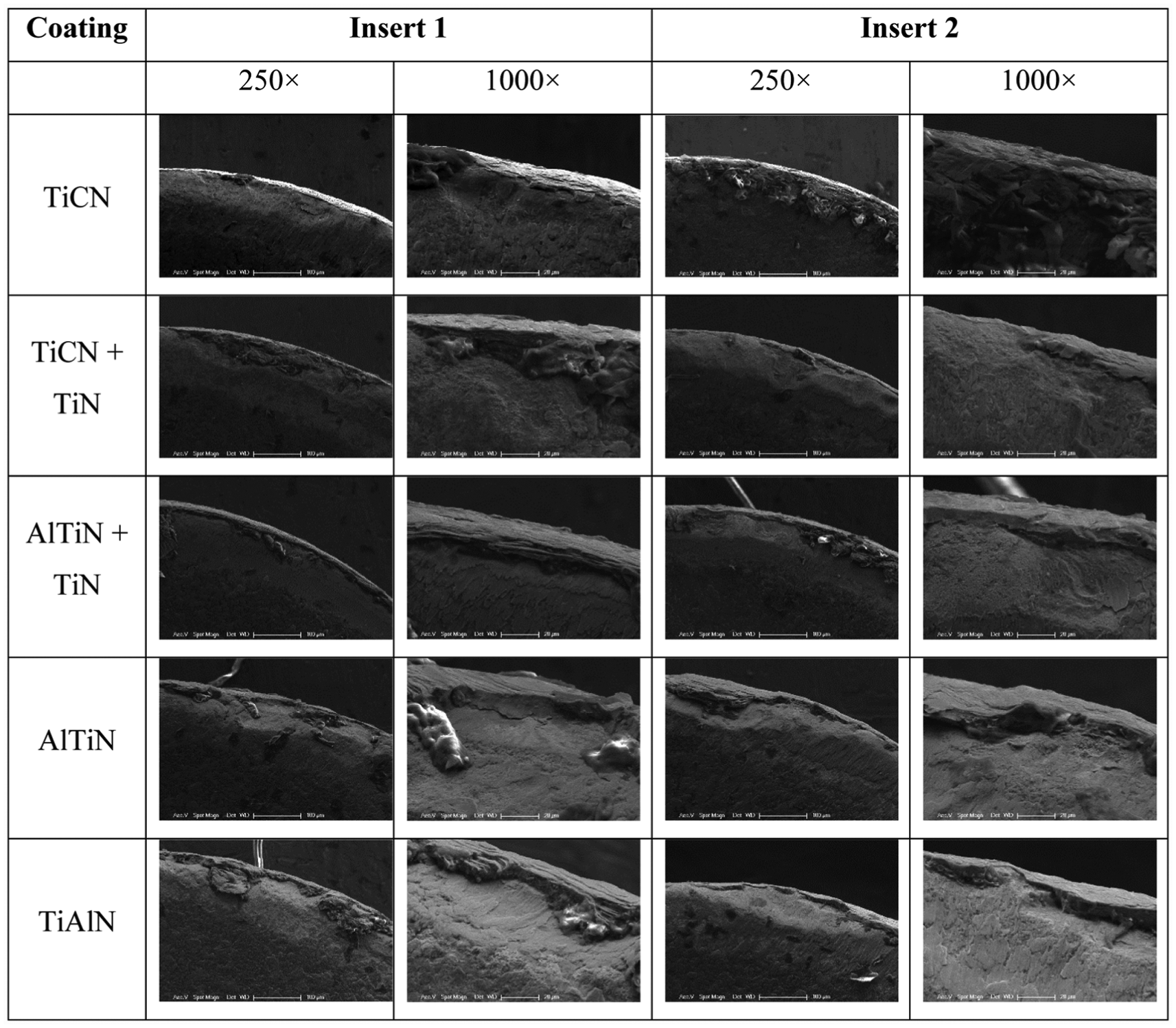
SEM micrographs of flank face for different coated inserts are depicted in Figure 2 for both inserts after a 3000 mm length of machining. Inserts 1 and 2 showed different tool wear values for all coated tools. In milling process, the result of wear difference between inserts was expected owing to the tool runout. The runout caused more chip removal of one tooth of the milling tool than the other(s). Detail SEM micrographs of the coated inserts are given in Figure 3 to understand tool wear modes and mechanisms. Mechanical crack was observed parallel to the flank face during high-speed milling of Ti6Al4V with TiCN-coated insert due to the cyclic mechanical loadings. Adhered workpiece material was also seen on the flank face of TiCN-coated insert, which was evidence of the presence of adhesion mechanism. The main tool failure modes and mechanisms were found to be abrasion, adhesion and chipping at the flank face for all coated inserts. Wang and Ezugwu 14 stated that chipping was one of the dominant failure modes when machining of Ti6Al4V alloy with PVD-coated inserts. These researchers explained this result with the combined action of high machining temperature, high mechanical stresses, high forces and chemical affinity of titanium alloy during machining. Mechanical crack was also seen at the flank face of TiCN-, TiCN + TiN- and AlTiN-coated cutting inserts. Adhesion on the flank face observed in high-speed milling of Ti6Al4V alloy no matter what coating material was employed. The adhesive wear was owing to the high pressure and temperature during milling process, 15 which accelerated the welding between tool flank face and surface of the workpiece. When high temperature and stress at the cutting area coupled with the brittleness of the cutting tool material, chipping occurred and accelerated. Similar result was explained by Jawaid et al. 16 during turning of Ti-6246 titanium alloy. Jawaid et al. 16 also stated that the mechanical and thermal loads occurred during machining process resulted in the formation of chipping.
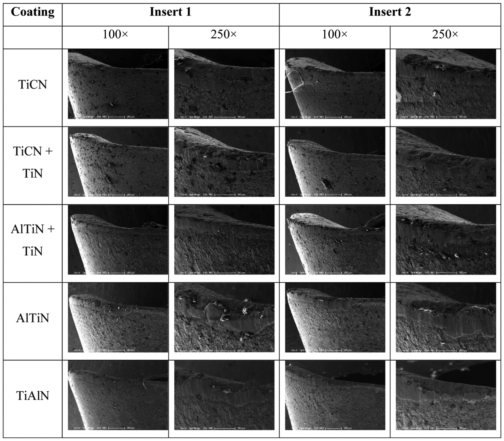
SEM micrographs of flank face for coated inserts after 3000 mm of milling.
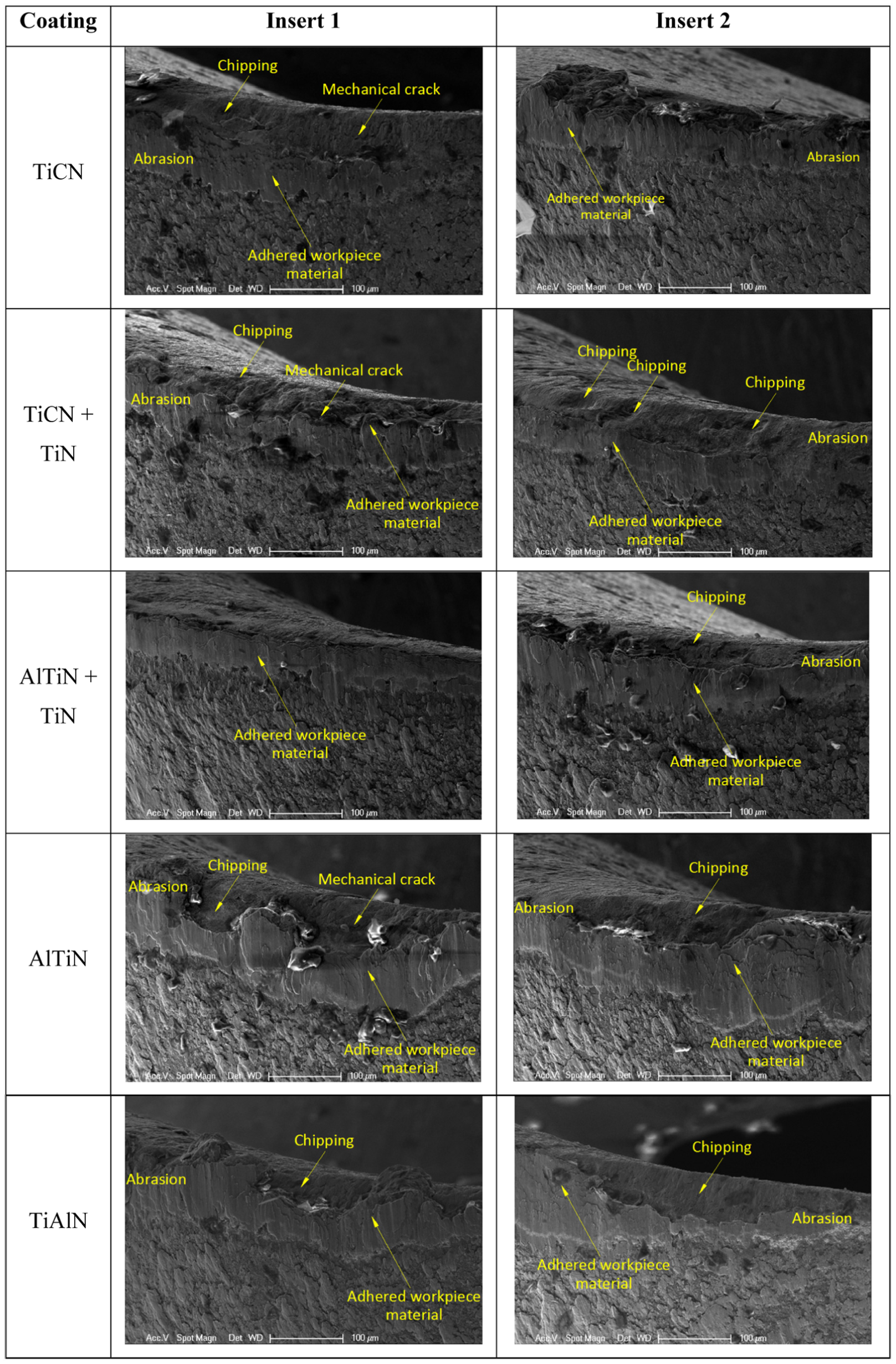
Detail SEM micrographs of flank face for coated inserts (magnification 250×).
Figure 4 shows maximum wear values on flank face for each coated insert. The final results of maximum wear on flank face were an average of two inserts. Experimental results indicated that the maximum tool wear increased with machining length for all coated inserts. From Figure 4, in terms of tool wear, the ranking of coated inserts from lowest to highest was as follows: TiCN, AlTiN + TiN, TiCN + TiN, TiAlN and AlTiN. In this study, TiCN-coated inserts gave lower wear than TiAlN-coated inserts, and this result was similar to the findings of Aramcharoen et al. 17 who carried out the experiments during the micro-milling of hardened tool steel (H13, 45 HRC). Higher hardness of TiCN-coated insert might be responsible for lower wear value. It was known that higher hardness of coated material improved the resistance to the mechanical wear. Also, Mativenga and Hon 18 found that TiCN-coated tool gave better performance than TiAlN-coated tool in terms of tool life during milling of H13 tool steel. In another study, Fallböhmer et al. 19 found that tool life of TiCN-coated tool was higher than AlTiN-coated tool during high-speed milling of H13 tool steel. It was found that TiCN-coated tool exhibited higher tool life than TiN + TiCN-coated tool during milling of AISI 1045 steel in the literature. 20 Higher hardness might be the reason why TiCN-coated inserts gave higher tool life.
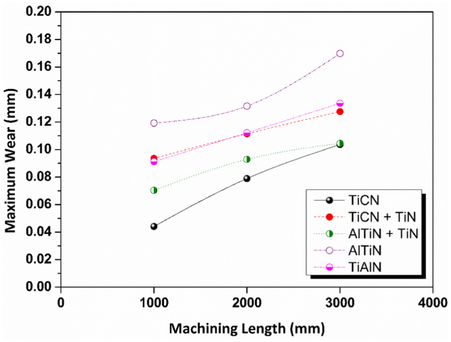
Maximum wear on flank face as a function of machining length for different coated inserts.
SEM micrographs of rake face for different coated inserts are given in Figure 5 for both inserts after a 3000 -mm length of machining. It was seen that adhesion of the workpiece materials on the rake face of the inserts occurred. This meant that there was a high stress and high temperature at the tool-chip contact area. Higher temperature and higher stress resulted in the thermal softening of workpiece materials and these caused the adhesion of workpiece material on the rake face of the inserts. This result was also observed during high-speed milling of titanium alloy in the literature. 21 At the rake face of some coated inserts, a crater wear was observed due to the high temperature at the tool–chip interface and the chemical affinity between the cutting tool and workpiece material. The formation of crater wear was the evidence of diffusion wear mechanism that was highly dependent on temperature at the cutting area. In the literature, similar results were observed.22–25
SEM micrographs of rake face for coated inserts after 3000 mm of milling.
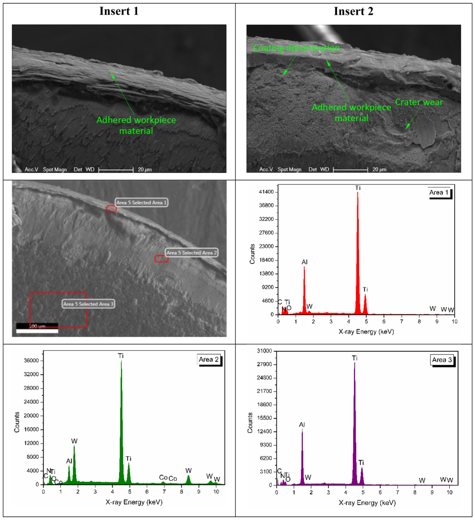
EDX analysis of the different coated inserts was carried out in the rake face and only results for ‘insert 1’ were given in this article. Results of wear on rake face for both inserts, and results of EDX for ‘insert 1’ are presented in Figures 6–10. When TiCN-coated inserts were employed, coating delamination and adhered workpiece material were observed on the rake face (Figure 6). Coating delamination was a result of residual stress of the coating, chemical reactions, mechanical impact and variable thermo-mechanical stresses. 26 Excessive reaction occurred during machining due to the higher chemical affinity between the tool coating and workpiece material. This high reaction resulted in the coating removal from the cutting edge. It was reported that adhesion occurring at the cutting tool–chip interface was the pioneer of the coating delamination during machining of Ti6Al4V. 27 Moreover, interrupted nature of milling process resulted in high frequency interrupted machining force at the cutting edges 28 and this was the reason why the coating chipped off easily in milling process. EDX analysis of TiCN-coated insert (selected area 1) showed the presence of titanium (Ti), aluminium (Al) and vanadium (V) confirming the workpiece material deposited on the cutting tool surface during high-speed milling. Due to the large plastic deformation, high strength at high temperature and work hardening of Ti6Al4V titanium alloy, the high temperature and large cutting force during machining caused high pressure on the tool–work contact area. Under these circumstances (high temperature and pressure), elements of the workpiece material were easily transferred to the cutting tool. 29 In ‘selected area 2’, the presence of tungsten (W) and cobalt (Co) elements was an indication of a coating delamination. In this area, it was also found that Ti, Al and V elements indicated the existence of adhering workpiece material. ‘Selected area 3’ was taken from unaffected zone by wear to confirm the coating material and this zone indicated the constituents of TiCN-coated insert.
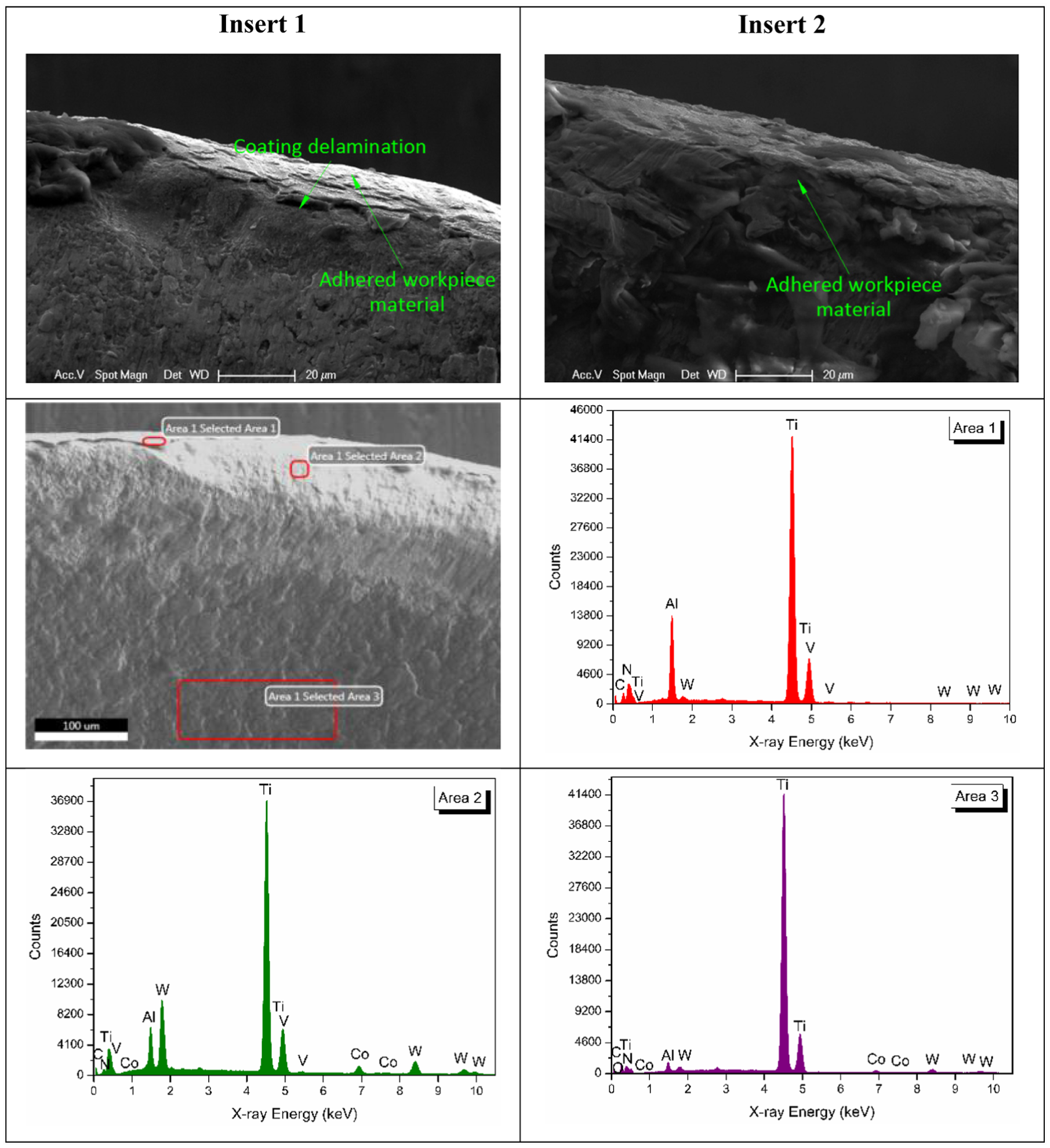
Wear on rake face and EDX spectra of TiCN-coated insert 1.
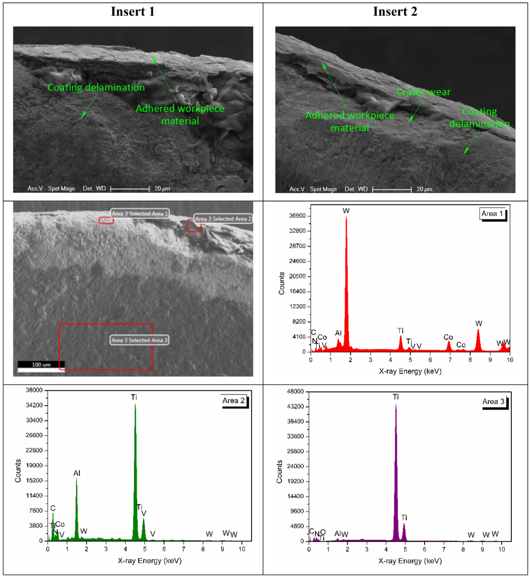
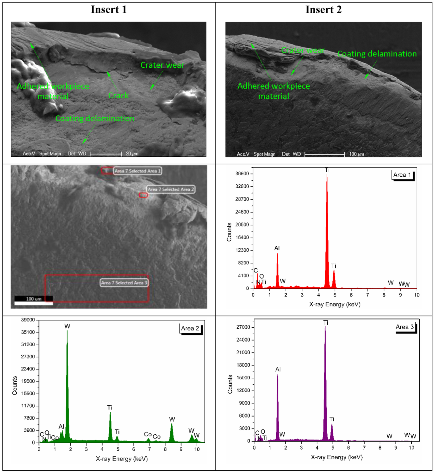
Wear on rake face and EDX spectra of TiCN + TiN-coated insert 1.
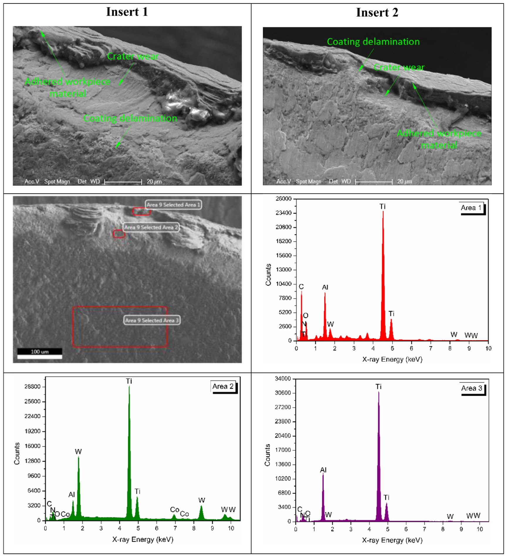
Wear on rake face and EDX spectra of AlTiN + TiN-coated insert 1.
Wear on rake face and EDX spectra of AlTiN-coated insert 1.
Wear on rake face and EDX spectra of TiAlN-coated insert 1.
When TiCN + TiN-coated inserts were used, coating delamination, adhered workpiece material and crater wear were observed on the rake face (Figure 7). EDX analysis of TiCN + TiN-coated insert in ‘selected area 1’ revealed that the coating was removed from substrate, where the presence of W and Co confirmed the removal of the coating material. It was concluded that Ti, Al and V elements in ‘selected area 2’ come from workpiece material confirming the adhesion mechanism. EDX analysis of unaffected region by wear (selected area 3) verified the elements (Ti, C and N) of coating material.
Coating delamination, adhered workpiece material and crater wear occurred on the rake face during high-speed milling with AlTiN + TiN-coated inserts (Figure 8). EDX analysis of AlTiN + TiN-coated insert in ‘selected area 1’ revealed the major components of workpiece material, which was an indication of adhesion mechanism. In ‘selected area 2’, the existence of W and Co elements was due to the coating delamination. In this area, it was also observed higher presence of Ti element, which indicated the transfer of this component from workpiece material to the cutting insert. EDX analysis of unaffected region by wear (selected area 3) confirmed the elements (Al, Ti and N) of coating material.
Coating delamination, adhered workpiece material, crater wear and crack were observed on the rake face during high-speed milling with AlTiN-coated inserts (Figure 9). EDX analysis of AlTiN-coated insert in ‘selected area 1’ gave a higher concentration of workpiece elements, indicating the formation of adhesion. In ‘selected area 2’, it could be concluded that the coating delamination occurred owing to the higher presence of W element. EDX analysis of unworn region (selected area 3) confirmed the components (Al, Ti and N) of coating material.
During high-speed milling with TiAlN-coated inserts, observed wear types on the rake face were as follows: coating delamination, adhered workpiece material and crater wear (Figure 10). In the ‘selected area 1’, a high concentration of Ti element was found, indicating adhesion of workpiece material to the cutting insert. W and Ti were the major elements detected in the ‘selected area 2’. The presence of W element was due to the coating delamination and the presence of Ti element was the indicator of the adhesion of the workpiece material to the cutting insert. EDX analysis of unworn zone (selected area 3) verified the elements (Ti, Al and N) of coating material.
Cutting force
In this study, cutting force was estimated by employing following equation

where Fx is force in X-direction and Fy is force in Y-direction.
Results of cutting forces during high-speed milling with different coated inserts are presented as a function of machining length in Figure 11. It was found that the maximum cutting force fluctuated with machining length and coated material. The variation of cutting force was due to the tool wear, the work hardening of the workpiece material, the thermal expansion of the tool and workpiece and the temperature fluctuation in the cutting tool–workpiece interface. 30 It was seen from Figure 11 that at the beginning of the machining pass, TiAlN-coated insert gave the lowest cutting force value. However, at the end of machining, the lowest cutting force was obtained with TiCN-coated insert. This was probably due to the early chipping occurrence of TiCN-coated inserts at the early stage of machining, which increased cutting force. In the literature, it was stated that the value of cutting force was dependent on the hardness of coating material. Higher hardness of coating material gave lower cutting force 31 and this was the reason why TiCN-coated tool gave lower force at the end of machining.
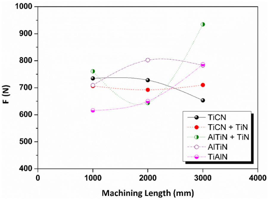
Cutting force results as a function of machining length for different coatings.
Surface roughness
The surface roughness values decreased or increased (random behaviour) with increasing machining length (Figure 12(a)). This random behaviour of surface roughness agreed with the studies published in the literature.32,33 This result could be attributed to the variation in hardness at the different regions of workpiece material. Temperature fluctuation at the tool–workpiece interface during machining might be also the reason for this conclusion. In some cases, the surface roughness value decreased with increasing machining length (Figure 12(a)). Similar result was found during milling of Ti6Al4V alloy by López de Lacalle et al. 34 These researchers explained this phenomenon with a flattening effect, which may be owing to the strong warming of the workpiece material during machining. 34
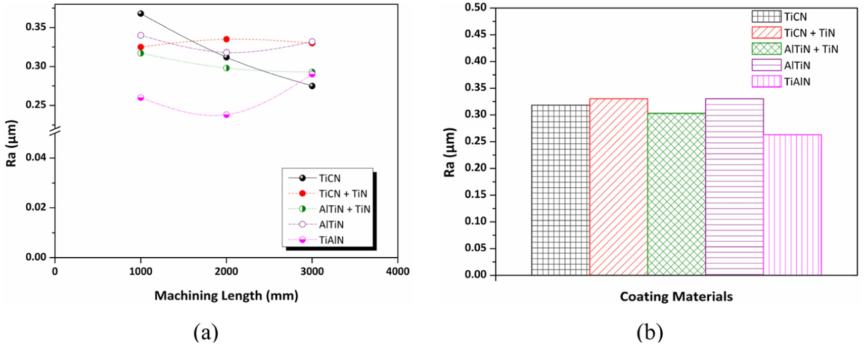
(a) Ra results as a function of machining length and (b) average Ra results for different coatings.
At the beginning of the machining pass, TiAlN-coated insert gave the lowest surface roughness value followed by the AlTiN + TiN-coated insert. At the end of machining, the lowest surface roughness was achieved with TiCN-coated insert.
For comparison purpose, average Ra for each coated insert was computed as the average of Ra results obtained with machining lengths 1000, 2000 and 3000 mm (Figure 12(b)). From this analysis, it was concluded that the lowest Ra value was achieved with TiAlN-coated insert followed by AlTiN + TiN-coated insert. In the literature, it was found that the surface roughness of P20 mould steel was lower during high-speed milling with TiAlN-coated tools than TiCN-coated tools, 19 and this result was similar to that of this study.
Chip morphology
Chip morphology versus the coating type and cutting pass is presented in Figure 13 with a magnification of 10×. It was observed that the shapes of the chips remained almost unaltered irrespective of coating material. Similar result during milling of Ti6Al4V alloy using aCN/TiAlN- and TiN/TiAlN-coated tools was also declared by Çalışkan and Küçükköse. 35 For both coated tools, serrated type chip was observed. 35 Serrated chip was observed during milling of titanium alloys 36 as seen in this study.
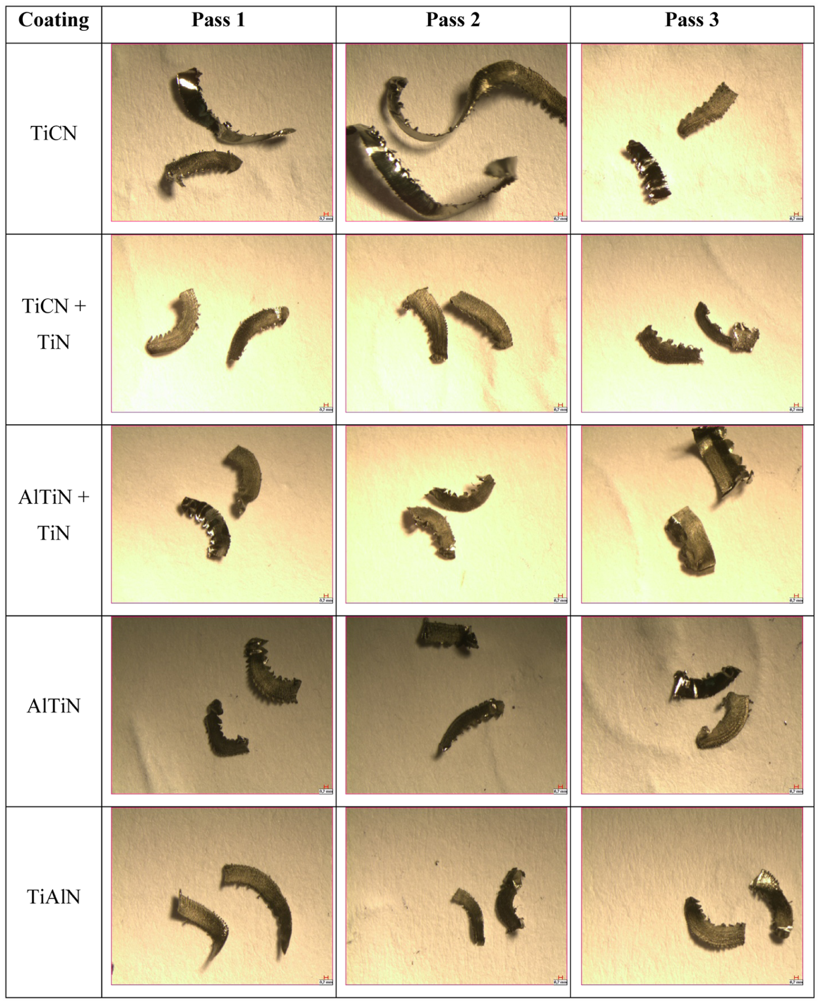
Chip morphology versus the coating type and machining pass.
Different chip morphologies were observed at the free and back surface of the chips as seen in Figure 14. It was observed that back surface of the chips was smoother and shinier than the free surface of the chips. This result was attributed to the combined effects of high contact pressures, temperatures and frictional forces. 37 These high contact and shear stresses occurred as the back surface slides over the rake face of the cutting tool. Also, rake face of the cutting tool constrained the deformation of the back surface. These two constrains were synergistic and caused the smooth back surface. 38 It was seen from Figure 14 that the structure of free surface was lamella. It was also observed from views of chips that chip serrations occurred across the width of the chips in all coating materials. These teeth are named as ‘primary serrated teeth’. At the upper or lower edge of the chips, serrated elements were observed. These larger elements are named as ‘secondary serrated teeth’. 39
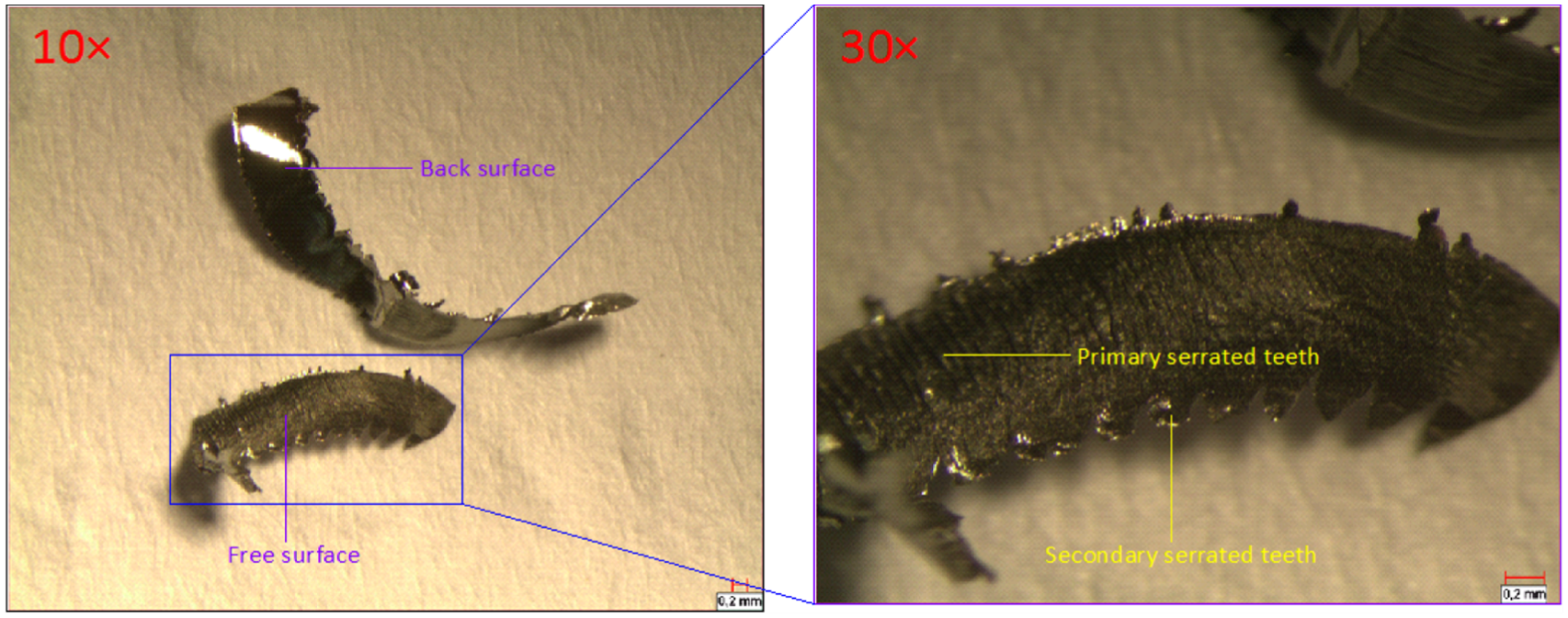
Back and free surfaces of chips.
Conclusion
In this study, a high-speed milling of Ti6Al4V titanium alloy was conducted with different coated inserts, namely, monolayer TiCN, AlTiN, TiAlN and two layers TiCN + TiN and AlTiN + TiN, which were deposited by PVD. Tool wear, cutting force, surface roughness and chip morphology were evaluated for these coated inserts. The conclusions of this study were as follows:
Abrasion, adhesion and chipping on flank face were observed during high-speed milling of Ti6Al4V titanium alloy with all coated inserts. In addition to these wear types, mechanical crack was observed when milling with TiCN-, TiCN + TiN- and AlTiN-coated inserts.
The maximum tool wear on flank face increased with machining length for all coated inserts. In terms of tool wear, the ranking of coated inserts from lowest to highest was as follows: TiCN, AlTiN + TiN, TiCN + TiN, TiAlN and AlTiN.
Coating delamination and adhesion on rake face were observed during high-speed milling of Ti6Al4V titanium alloy with all coated inserts. Also, crater wear occurred during milling process with all coated inserts except for TiCN-coated inserts. Crack on rake face was only observed with AlTiN-coated insert.
EDX analysis conducted on rake face confirmed the presence of coating delamination and adhesion.
Maximum cutting force and surface roughness fluctuated with coating material and machining length. At the beginning of the machining pass TiAlN-coated insert and at the end of machining TiCN-coated insert gave the lowest cutting force and surface roughness.
Chip morphology was found to be unaltered irrespective of coating material.
Footnotes
Acknowledgements
The author acknowledges Professor Babur Ozcelik, to whom the author dedicates this article, for providing the cutting tools and materials employed in the experiments. The author also acknowledges Onder Gedik for helping with experimental study and Ahmet Nazim for helping with SEM measurements.
Declaration of conflicting interests
The author(s) declared no potential conflicts of interest with respect to the research, authorship and/or publication of this article.
Funding
The author(s) received no financial support for the research, authorship and/or publication of this article.