
Abstract
Titanium alloys are widely used in aeronautics that demands a good combination of high strength, good corrosion resistance and low mass. The mechanical properties lead to challenges in machining operations, such as high process temperature as well as rapidly increasing tool wear. In this work, three carbide end mills have been used in machining of titanium alloy Ti-6Al-4V. The first tool is coated with TiAl; the second and the third are coated with multi-layers or with a single layer of TiAlN. The cutting force and the tool life have been experimentally investigated and put into relationship with the process parameters under dry cutting condition. The quality of the machined surfaces has been evaluated by measuring the roughness of the machined surfaces. Finally, the correlation among cutting force variation, tool wear propagation and surface roughness has been analyzed and discussed. These three tools demonstrate to be able to maintain their hardness and other mechanical properties at the high cutting temperatures that they encountered.
Introduction
Titanium alloys are widely utilized in the aerospace, biomedical, automotive and petroleum industries due to their high mechanical properties, heat resistance and corrosion resistance.1,2 One of the popular titanium alloys for these applications is Ti-6Al-4V. Specifically, Ti-6Al-4V alloy has low modulus of elasticity and exhibits severe plastic deformation, severe wear and breakage with high-speed machining (HSM). On the other hand, this important alloy has a low thermal conductivity and it reacts chemically with tool materials. This involves an increase of the load and of the temperature on the cutting tool up to its extreme abrasion.3–5 It is a typical alpha–beta titanium alloy. 6
Tool wear in cutting processes is defined as the amount of volume loss of tool material on the contact surfaces due to the interactions between the tool, chip and workpiece. During a cutting process, as a consequence of the high temperature and the high contact stresses at the tool–chip interface, the titanium chip maintains a very intimate contact with the tool on each of the rake and flank surfaces7,8 through interfacial layers. Therefore, tool wear in cutting titanium alloys is reportedly due to adhesion and diffusion of tool material into the flowing chip at the tool–chip interface. Tool wear involves vibrations on the machine tool and deterioration of the quality of the workpiece. It even causes tool and workpiece damage as well as downtime of the machine tool when the tool is badly worn. Automation in machining has spread fast in the last few decades, and unattended machining has been widely introduced in many machine shops. So on-line monitoring of cutting condition and tool wear is a key technique that realizes high efficiency and automation in machining. Various tool wear monitoring techniques have been developed to enhance the operation efficiency of automated manufacturing systems. Among the on-line tool wear monitoring methods, the cutting force’s signal is the most commonly used variable as a tool wear indicator during automated manufacturing because the measurement of cutting forces is fairly simple and straightforward.9,10 Exploring the correlation between cutting force variation and tool wear propagation is of great importance to the development of an effective tool condition monitoring strategy. 11 Thus, a sound knowledge of cutting forces is crucial to generate further insight into tool wear, tool life and surface roughness. With the wide use of computer numerical control (CNC) machine tools together with high-performance computer-aided design/computer-aided manufacturing systems, HSM has demonstrated advantages over traditional machining techniques, such as increased productivity, high-quality surface, burr-free edges and virtually stress-free components. 12 The increasing demand for higher machining efficiency has led to a much more reliable monitoring condition of the machining process. However, there are few studies on the correlation between cutting force variation and tool wear propagation during high-speed dry cutting of Ti-6Al-4V alloy. A recent study shows that coated carbide tools may be used to machine Ti-6Al-4V alloy over a wide range of cutting conditions by producing variation in chip morphologies. 13 Another study presents a special kind of tools that allow to reduce the cutting forces and to increase tool life during dry machining of Ti-6Al-4V. 14 Surface textures were made on the rake and flank face of cemented carbide inserts by laser machining, and the resulting grooves are filled by molybdenum disulfide solid lubricants. A further study presents the formation of both the segmented chip, due to a cyclic cutting force, and the continuous chip, due to a static force, during turning of Ti-6Al-4V alloy at low cutting speed and large feed rate. 15 An article studies the machining behavior of Ti-5553 and Ti-6Al-4V alloys in different interrupted cutting operations using Physical Vapor Deposition (PVD) coated cemented carbide tools. 16 An article presents an experimental based work with geometrical analysis for better understanding of effects caused by thread milling geometry, cutting conditions and tool angles on cutting forces. 17 The effects of the minimum quantity lubrication applications with different oil supply rates in high-speed end milling of Ti-6Al-4V has been investigated in Cai et al. 18 An article by Jaffery et al. 19 presents an investigation into the wear of cutting tool during milling operation of Ti-6Al-4V using H13A carbide inserts, while an article by Pan et al. 20 investigates the performance of polycrystalline diamond tools in the end milling of titanium alloys (Ti-6Al-4V) by using small customized cutting tools.
The main objective of this work is to experimentally investigate the cutting force variations and the tool life during milling of Ti-6Al-4V alloy with three different coated tungsten carbide inserts under dry cutting condition. The quality of the machined surfaces has been evaluated by means of roughness. Finally, the correlation among cutting force variation, tool wear propagation and surface roughness has been analyzed and discussed.
Experimental procedures
Workpiece material
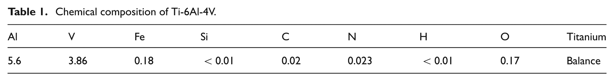
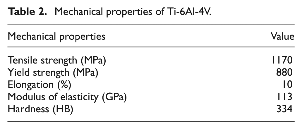
The workpiece material used in the experiment was Ti-6Al-4V with chemical composition shown in Table 1. Its mechanical properties are shown in Table 2.
Chemical composition of Ti-6Al-4V.
Mechanical properties of Ti-6Al-4V.
Cutting tool materials
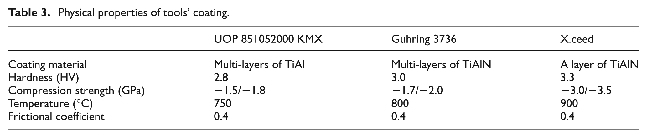
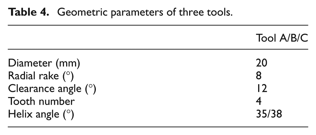
Three end milling cutters with three types of coating were used for milling of Ti-6Al-4V. Tool A is a carbide mill coated by multi-layers of TiAl (it is called UOP 851052000 KMX). Tool B is a carbide mill coated by multi-layers of TiAlN (it is called Guhring 3736). Tool C is a carbide mill coated by a single layer of TiAlN (it is called X.ceed). All the three tools have a variable pitch helix. The physical properties of Tools B and C are given in Table 3. Tools have been rigidly fixed to a tool holder with a nominal diameter of 20 mm. Geometric parameters of the three tools are given in Table 4.
Physical properties of tools’ coating.
Geometric parameters of three tools.
Machining test
The experiments have been carried out on a Brembana Macchine CNC machining center with a maximum power of 15 kW and a maximum spindle speed of 15,000 r/min. Samples of Ti-6Al-4V with dimensions of 150 mm × 50 mm × 50 mm have been tested. Three values of cutting speed v (38, 63 and 88 m/min), four values of radial cutting depth d r (5, 10, 15 and 20 mm) and one value of both feed f (0.075 mm per tooth) and axial cutting depth d p (0.5 mm) have been taken into account. They have been chosen in order to reproduce the typical cutting conditions used in the manufacturing industry. Each cut has been replicated three times, yielding a total of 36 tests for each tool and, therefore, 108 tests in all. The experimental cuts have been performed in a random sequence, in order to reduce the effect of any possible systematic error.
The cutting force signal has been acquired along the whole cut. A Kistler three component force dynamometer (type 9257BA) has allowed to measure the dynamic cutting force components (F x, F y and F z), as shown in Figure 1. The titanium sample has been mounted on the dynamometer. F x and F y have been measured on the cutting plane where F y is in the direction of the feed and F x is perpendicular to it, while F z is in the direction of the axial depth of cut perpendicular to the cutting plane. The signal acquired by the dynamometer has been sampled at different frequencies and for different time intervals, in order to set the acquisition parameters that gave the whole information about force signal with the minimum time waste. Therefore, the output of the dynamometer has been fed into an A/D converter and it has been sampled at 10 kHz by a PC. The raw cutting force data have been transformed into time domain.
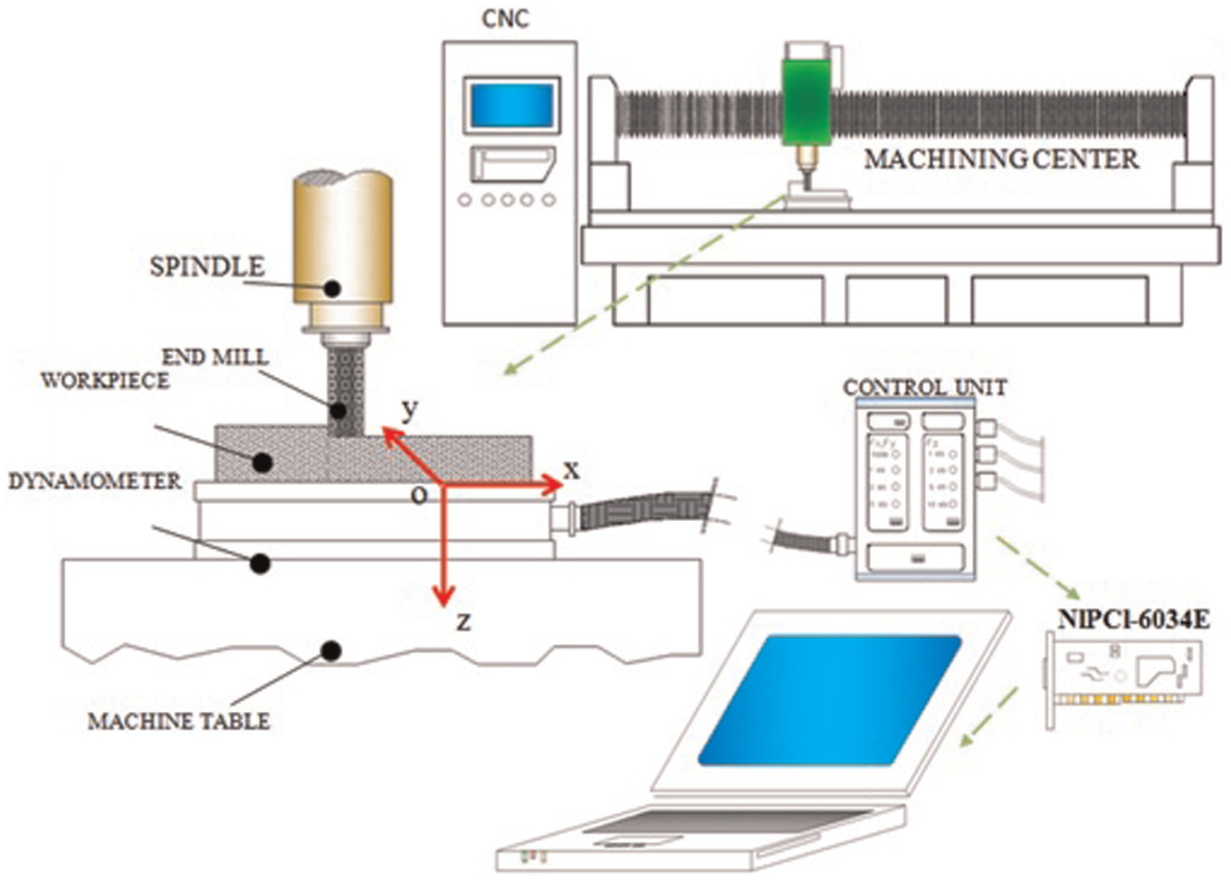
Scheme of a sample mounted on dynamometer.
Some further tests have been planned to evaluate the tool life. The same three values of cutting speed v (38, 63 and 88 m/min), one value of radial cutting depth d r (20 mm), one value of both feed (0.075 mm per tooth) and axial cutting depth (2 mm) have been taken into account. They have been chosen by taking into account both the suggestions of the tool’s manufacturer and the minimum values proposed by the ISO 8688 standard. Each cut has been replicated three times, yielding a total of 9 tests for each tool and, therefore, 27 tests in all. The experimental cuts have been performed in a random sequence, in order to reduce the effect of any possible systematic error. Tool flank wear of the insert has been measured by means of an optical microscope by breaking off the machining every 15 min, in reference to ISO 8688-2. Hence, the average flank wear was chosen as the tool failure criterion, and the tools were discarded when the average flank wear reached 0.30 mm or when catastrophic fracture of the edge was observed.
The surface roughness of the workpiece was measured by a stylus instrument. To measure roughness of the surface of the workpiece, the cut-off length was taken as 0.8 mm and the sampling length as 5.6 mm.
Results and discussion
Cutting force
Figures 2 and 3 show typical time domain signals monitored in the XY plane, where Y is the direction of the feed, X is the perpendicular to it and Z is in the vertical direction perpendicular to XY plane. Figure 3 is for the resultant force of F x and F y, it is indicated as R xy. As can be seen in these figures, the force signals are periodic and regular. After the signal has been stored, a feature extraction program in LabView® environment has calculated the average value of the cutting force along the three axes.
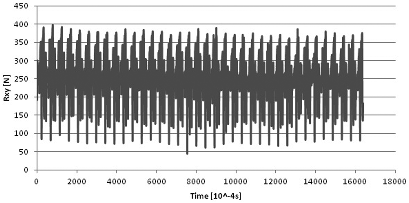
R xy signal in time domain.
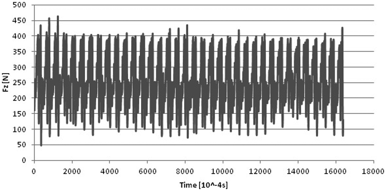
F z signal in time domain.
The maximum value and the standard deviation of the signals F z and R xy have been evaluated and put into relationship with the process parameters.
The analysis of variance (ANOVA) has provided that the cutting speed significantly influences both the maximum value and the standard deviation of F z signal for all the three considered tools (see Figures 4 and 5). In particular, the values increase with the cutting speed. However, the radial depth of cut seems not to influence the maximum value of F z signal, while it involves a decrease of the standard deviation when it increases. The same results have been found for R xy signal.
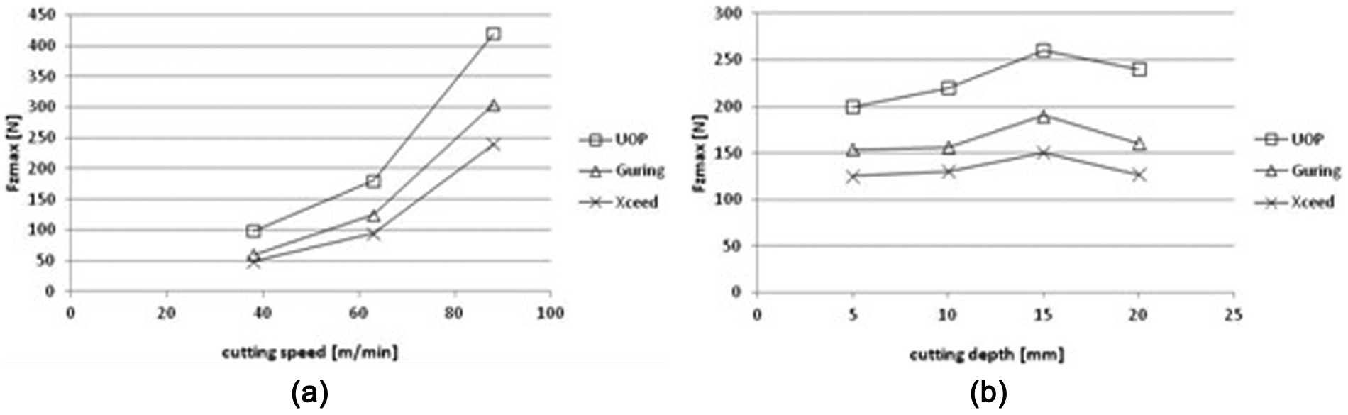
F zmax versus (a) cutting speed and (b) cutting depth.
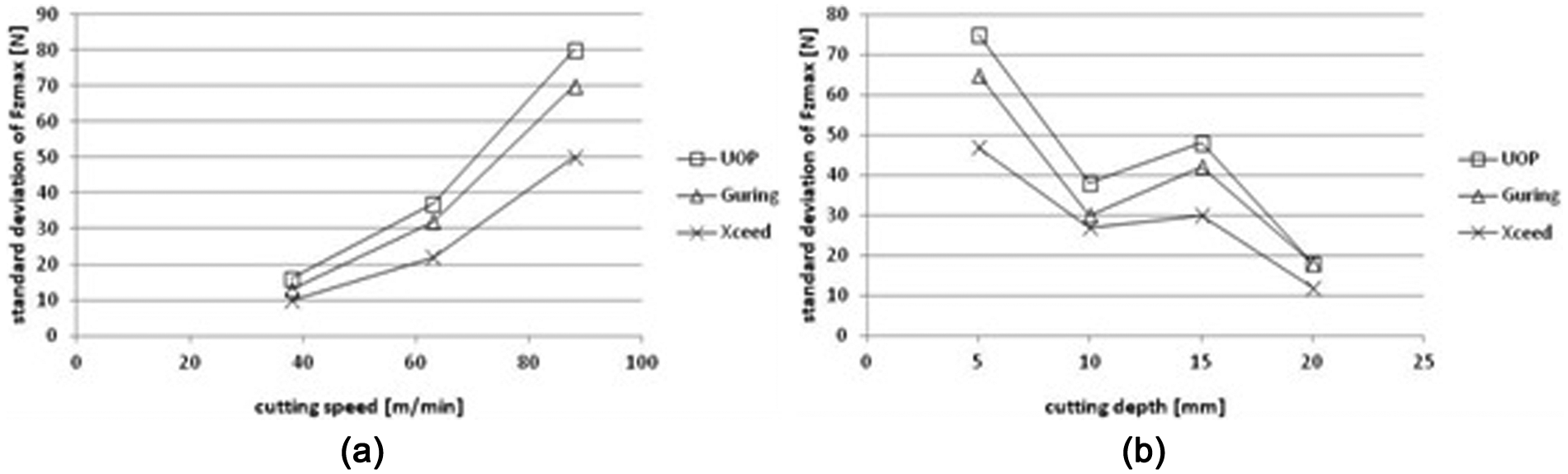
Standard deviation of F z versus (a) cutting speed and (b) cutting depth.
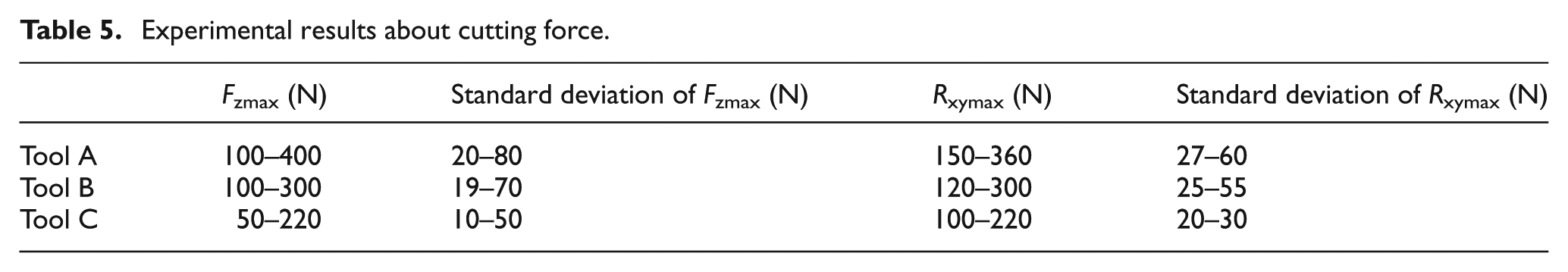
The maximum values and the standard deviations of F z and R xy are shown in Table 5 for the three considered tools. Tool C involves the smallest values of cutting force, since the measured maximum value of both F z and R xy is smaller than that due to the other tools, and the standard deviation estimated by the measurements is smallest too. In particular, it reduces the maximum value of both F z and R xy by more than 20% when compared with Tool A and B. This is probably due to the fact that Tool C has the highest value of hardness and of cutting temperature.
Experimental results about cutting force.
Tool life
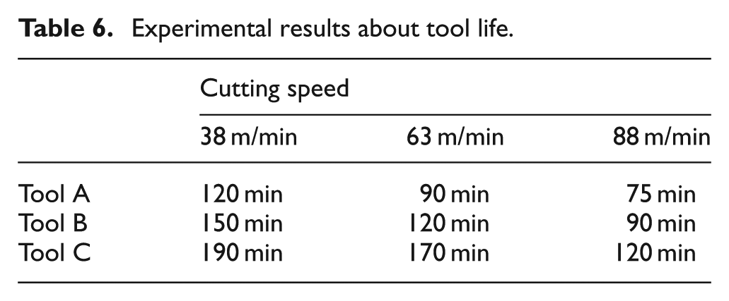
Average flank wear with cutting time of the three tools is shown in Figure 6 for a cutting speed of 38 m/min. The tool life of Tool C is much longer than that of Tools A and B under the same cutting conditions. From Figure 6, it can be seen that the tool life of Tool C is about 190 min when milling Ti-6Al-4V with a cutting speed of 38 m/min, while at the same cutting condition, the tool life of Tools A and B is only 120 min and 150 min, respectively. With the increase of cutting speed, the temperature of the cutting region increases and, therefore, tool life decreases. Tool life of Tool C is 120 min with a cutting speed of 88 m/min, while at the same condition, tool life of Tools A and B is 75 min and 90 min, respectively (see Table 6). It is possible that diffusion across the interface results in the formation of a titanium carbide layer which would then protect the tool in forming a barrier to further diffusion and loss of tool material in the chip, as discussed in Honghua et al. 21 However, this assumption requires further investigations.
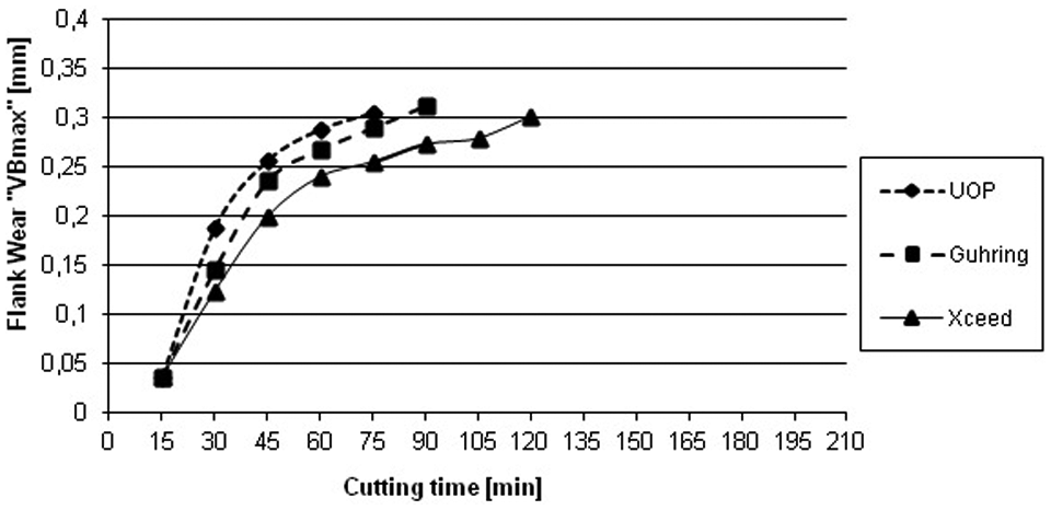
Average flank wear versus cutting time of the three tools.
Experimental results about tool life.
Surface integrity
Surface roughness average values of machined surface with the three different tools versus the considered process parameters are shown in Figure 7 and Table 7. Surface roucghness average value of the machined surface in milling of Ti-6Al-4V with Tool A increases from 1.7 to 2.4 µm, when the cutting speed increases from 38 to 88 m/min. Moreover, surface roughness average value due to Tool A decreases by increasing the radial depth of cut, even if it remains around 2 µm.
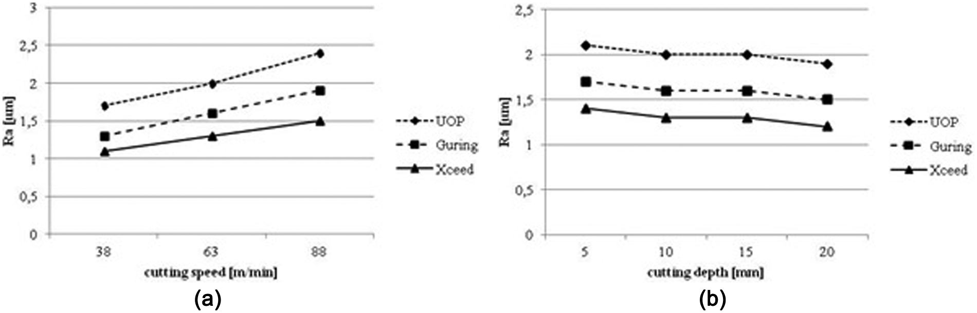
R a versus (a) cutting speed and (b) radial depth of cut for the three tools.
Experimental results about surface integrity.
The trends due to Tools B and C are similar to those of Tool A, even if the ranges are from 1.3 to 1.9 µm for Tool B and from 1.1 to 1.5 µm for Tool C.
Therefore, it may be observed that the surface roughness due to Tool C is smaller than that of the other tools, even if its minimum value is 1.1 µm, such that grinding or polishing would be required.
Conclusion
The experimental results show that the X.ceed tool involves the lowest cutting force to dry machine Ti-6Al-4V. This is probably due to the fact that X.ceed shows the highest value of hardness and of cutting temperature. The tool life of X.ceed is much longer than that of UOP 851052000 KMX and of Guhring 3736 under the same cutting conditions in milling of Ti-6Al-4V alloys. The average surface roughness produced during machining by the X.ceed tool is the smallest when it is compared to the other two end mills. The X.ceed tool seems to be the most functionally satisfactory cutting tool for machining Ti-6Al-4V alloys that are commercially available.
The value of the process parameters should be chosen by taking into account that increasing the cutting speed causes an increase of the cutting force, but an increase of the surface quality too. In the same time, an increase of the radial depth of cut improves the surface quality without involving an increase of the cutting force.
Footnotes
Declaration of conflicting interests
The authors declare that there is no conflict of interest.
Funding
This work was carried out with the funding of the Lazio Region and Ministry of Instruction, University and Research (MIUR).