
Abstract
Tungsten carbide cutting tools with and without solid lubricant (WC-10Co-5CaF2 and WC-10Co) were developed in-house via powder metallurgy. The developed cutting tools and a commercial WC-10Co cutting tool were used to machine cylindrical AISI 1020 steel material under dry conditions. The cutting force and average cutting tool temperature were continuously measured. The cutting tool flank surface and chip morphology after specific tool life (5 min of cutting) were examined to understand tool wear. The flank wear of the considered cutting tools was also measured to quantify the cutting tool life. The surface roughness of the workpiece was measured to determine the machining quality. The developed cutting tool with solid lubricant (WC-10Co-5CaF2) generated 20%–40% less cutting force compared to that of the developed cutting tool without solid lubricant (WC-10Co). In addition, the finish of the workpiece surface improved by 16%–20% when it was machined by the solid lubricant cutting tool. The cutting tool with solid lubricant (WC-10Co-5CaF2) exhibited a 15%–18% reduction in flank wear. Curlier and smaller saw tooth chips were generated from the WC-10Co-5CaF2 cutting tool, confirming that less heat was generated during the cutting process, and the finish of the machined surface was also improved.
Introduction
In recent years, many manufacturing industries have shifted their focus towards green manufacturing by machining in the absence of coolants. However, the disadvantages of dry machining, which include poor tool lifetime and extended production time, restrict wide application. Extensive research and development is being conducted to develop cutting tools with improved wear resistance, and procedures such as texturing, coating and the addition of solid lubricants are often performed.1 –7
Xing et al. 1 developed textured Al2O3/TiC cutting tools and burnished MoS2 into the textures. The developed cutting tool, which possessed wavy micro-scale textures on the rake face, exhibited superior wear resistance compared to other cutting tools. Xing et al. 2 also coated WS2/Zr on textured Al2O3/TiC ceramic cutting tools and showed that the textured tool was effective for machining hardened steel, as well as reducing the cutting force, cutting temperature, and friction between tool–chip interfaces. Deng et al. 3 developed Al2O3/TiC with CaF2 through a milling, compacting and sintering route. Hardened steel and cast iron were machined using the developed cutting tool materials. The friction coefficient between the chip and Al2O3/TiC/CaF2 ceramic cutting tools was lower due to the formation of a self-lubricating film on the tool–chip interface. Deng et al. 4 drilled micro-holes on the rake and flank surface of WC/Co tools and filled the holes with MoS2. The cutting forces and friction coefficient of the self-lubricated tools were significantly lower, and micro-holes on the rake surface exhibited less force than those at the flank surface. Deng et al. 5 developed an Al2O3/TiB2 cutting tool through hot pressing and sintering. The oxidation product of TiB2 grains acted as a lubricant to increase the wear resistance and reduce the coefficient of friction. Deng et al. 6 coated WS2 by physical vapour deposition (PVD) on textured WC/TiC/Co cutting tools and found that textured and WS2-coated cutting tools experienced less cutting forces compared to conventional and textured cutting tools. Lei et al. 7 drilled micro-holes on the rake surface of tungsten carbide inserts and used oil and tungsten disulphide to fill the micro-holes. Both liquid and solid lubricants were found to be equally effective at reducing the contact length and coefficient of friction at the chip–tool interface. An advanced Al2O3/(W,Ti)C/CaF2 multi-component graded self-lubricating ceramic cutting tool material was developed. 8 The cutting tests show that this multi-component graded self-lubricating ceramic cutting tool has better wear resistance than the homogeneous cutting tool. The performance of solid lubricant-assisted machining has been studied in comparison with that of wet machining. 9 The results indicate that there is a considerable improvement in the process performance with solid lubricant-assisted machining as compared to that of machining with cutting fluids. Surface texturing was made on the rake face of the WC/Co carbide tools, and molybdenum disulphide solid lubricants were filled into the textured rake face. 10 Lubricating film with low shear strength at the tool–chip interface, which was released from the texturing and smeared on the rake face and served as lubricating additive during dry cutting processes. Micro-holes were made on the surface of WC/TiC/Co carbide, and MoS2 solid lubricants were filled into these micro-holes. 11 The cutting forces, temperature and friction coefficient at the tool–chip interface of the tool embedded with solid lubricants were reduced compared with that of the conventional of self-lubricating film at the tool–chip interface, which was released from the micro-hole and smeared on the rake, and served as lubricating additive. A new type of self-lubricating ceramic cutting tool material with the addition of metal-coated solid lubricant powders was developed. 12 Nickel-coated CaF2 composite powders with core–shell structure were produced. Cutting tests show that the new type of self-lubricating ceramic cutting tool has better antifriction property and wear resistance than the corresponding cutting tool. Shaji and Radhakrishan 13 investigated the feasibility with a variety of solid lubricants and the development of grinding processes. Improved process results were obtained with solid lubricant application. Micro- and nano-solid lubricants, namely, boric acid and molybdenum disulphide are mixed with coconut and sesame oils separately and sonicated thoroughly. 14 It is observed that performance of nanofluids is better than micro-fluids in reducing cutting temperatures, cutting forces, tool flank wear and surface roughness of the machined surface. Kishawy et al. 15 developed electrostatic micro-solid lubricant–coated tools, using MoS2. Cutting forces and cutting temperature were measured and chip morphology were examined with and without coating. Results were compared with finite element simulation. Paturi and Narala 16 also developed electrostatic micro-solid lubricant–coated tools. In this investigation, feed forces were measured along with cutting forces, and coefficient of friction was computed. In addition to the chip morphology, average tool flank wear was also measured. Ramana et al. 17 prepared petroleum-free lubricant by mixing two canola oil and nano-crystalline boric acid, and performance evaluation was carried out.
In another study, tungsten carbide was added, along with various amounts of calcium fluoride, and milling and compacting characteristic analysis were carried out to determine the transverse rupture strength. 18 The effects of tungsten carbide and calcium fluoride addition were evaluated by assessing the friction and wear performance under abrasive and adhesive conditions.19,20
According to the literature, sufficient investigations have been carried out to improve the wear resistance of cutting tools through texturing, coating, and the addition of solid lubricants. Based on the above literature, commonly used cutting tool materials, such as tungsten carbide and thermally stable calcium fluoride, have not been previously considered for the development of solid lubricant cutting tool materials. In this study, tungsten carbide and calcium fluoride cutting tools were developed by powder metallurgy to understand the ability of calcium fluoride in tungsten carbide to withstand severe sliding wear at elevated temperatures.
Experimental procedure
Materials and processing
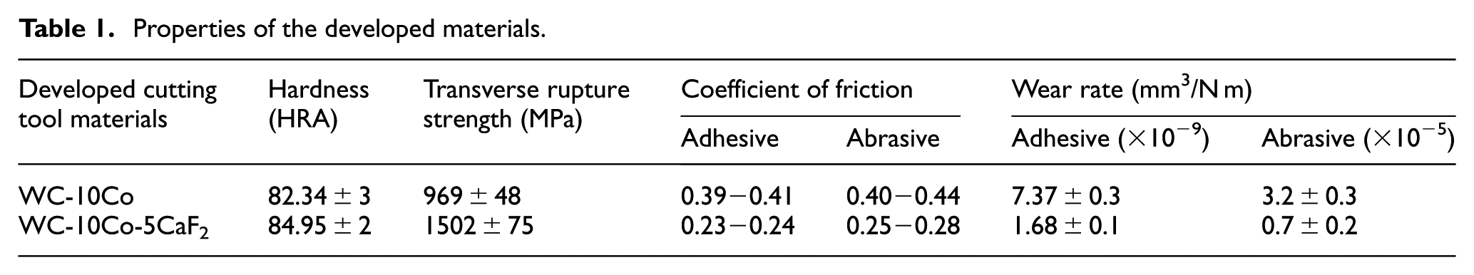
Tungsten carbide (WC) with a size and purity of 15–18 µm and 99.8% (Rapicut Carbides), respectively, was used as a basic cutting tool material due to its high hardness, good strength and excellent wear resistance. Cobalt (Co) with a size and purity of 20–30 µm and 99.5% (Loba Chemie), respectively, was used as a binder, and commonly used 10 wt% Co was utilised for the development of WC-based composites.8–10 Calcium fluoride (CaF2) with a size and purity of 170–180 µm and 98% (Loba Chemie), respectively, was employed for the cutting tools because it typically offers lubrication, even at higher temperatures. Typically, 1–5 wt% of stearic acid is used an additive; thus, 4 wt% stearic acid was added in this study. The aforementioned materials were milled in a planetary ball mill (PBM07; Insmart Systems) under a nitrogen (0.5 kg/cm2) atmosphere. The plate and bowl speed was set to 90 and 207 r/min, respectively, and a powder to ball ratio of 1:5 was applied. The above-mentioned plate speed and powder ball ratio were selected to avoid contamination. WC was milled with 10 wt% of Co and 5 wt% of CaF2 for 40 h. In accordance with ASTM B331-95, green compacted test specimens (40 × 16 × 5 mm) were compacted uniaxially at a pressure of 200–400 MPa using a tensile testing machine (UTE 20). Subsequently, the test specimens were sintered in a tube furnace (Okay 70T7; Bysakh) under a nitrogen atmosphere (0.5 kg/cm2) to prevent oxidation. The methodology used for the development of cutting tool material has been reported elsewhere. 18 The abrasive and adhesive wear performance of the developed cutting tool materials was evaluated,19,20 and Table 1 provides a summary of the mechanical and wear properties of in-house-developed WC-10Co-5CaF2 and WC-10Co materials. In this work, the developed cutting tool materials were cut in to 12 × 10 × 5-mm pieces and were brazed on the tool shank (ISO 6 R2020 P30). Subsequently, the cutting tool was ground to obtain a rake angle (γo) of 4°, a clearance angle (αo) of 15° and a nose radius of 0.3 mm. Figure 1(a) shows the considered cutting tools. Lei et al. 7 utilised a textured tungsten carbide cutting tool to machine mild steel material using similar cutting tool geometries (5° rake angle and 15° clearance angle).
Properties of the developed materials.
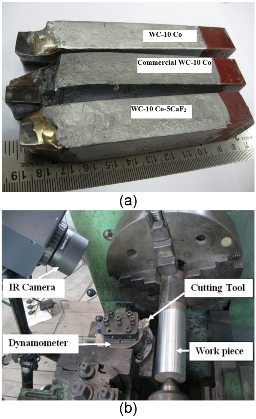
View of (a) the cutting tools and (b) the machining process.
Machining conditions
Turning was conducted to investigate the machining performance of the developed cutting tools. Cutting was performed with three different cutting tools including the following: (a) in-house-developed WC-10Co-5CaF2, (b) in-house-developed WC-10Co and (c) commercial tungsten carbide insert (WC-10Co, 1250 HV; Miranda Tools). Machining was carried out using a lathe (LB17; Chamundi) mounted with a four-component, piezo-electric dynamometer (9272; Kistler). During turning, all three force components were measured and continuously acquired on a personal computer. In this investigation, the net average temperature of the cutting zone was measured using a thermal imaging camera (VarioCAM hr head 480SL; InfraTec). The emissivity of the cutting tool was set to 0.85, and a small region was chosen to measure the temperature while machining.
Steel (AISI 1020) with an initial diameter of 62 mm and a HB hardness of 140 was machined using the three cutting tools. Each workpiece was machined to possess a cutting length of 150 mm and a depth of cut of 0.5 mm at a cutting speed of 80–100 m/min and a feed rate of 0.3 mm/rev under dry conditions. The same machining conditions were applied for three passes (i.e. a total cutting length of 450 mm); hence, a total cutting period of 5 min was considered for the cutting tool lifetime and tool wear investigation. Figure 1(b) shows the cylindrical workpiece in the lathe, which contained a dynamometer and infrared camera. The rake surface of the cutting tool after machining and the machined chip morphology were examined using a scanning electron microscope (1430vp; LEO). The initial and final surface roughness of the workpiece was measured using a contact type surface measurement device (Surftest SJ-400; Mitutoyo). Machined surfaces were examined using a non-contact three-dimensional profiler (CCI MP; Taylor Hobson) to determine the mechanism of material removal.
Result and discussion
Cutting forces
The measurement of cutting forces during machining enables the researcher to understand the machinability of the workpiece material, as well as the power consumption of the process. In addition, the surface quality of the workpiece and cutting tool lifetime can be determined by measuring the cutting forces. Figure 2(a)–(c) shows the cutting, feed and radial forces generated by the in-house-developed and commercial cutting tool at a cutting speed of 80 m/min. The measured cutting, feed and radial force represent the tangential, axial and radial components of the cutting, respectively. All of these forces increased gradually and then fluctuated around a mean value. The main cutting force generated by the considered cutting tools is provided in Figure 2(a). As shown in the figure, the WC-10Co-5CaF2 cutting tool exhibited a 20% reduction in the cutting force. The presence of solid lubricants on the rake and flank surfaces of the cutting tool reduced the frictional resistance of workpiece/chip interactions. Figure 2(b) shows the force generated by the feed, and Figure 2(c) shows the radial force generated by the considered cutting tools. Compared to the other investigated cutting tools, all of the cutting forces components decreased when the workpiece was machined with the solid lubricant cutting tool. Thus, the observed reduction in the cutting force in all three directions was attributed to the decrease in resistance. The magnitude of the cutting force was greater than that of the feed and radial forces, similar to most machining conditions. The radial force was the lowest compared to the cutting and feed forces. The ratio of the cutting force, feed force and radial force varies with the approach angle, geometry of the cutting tool and feed rate. 21 During the turning process, the magnitude of the cutting force was greater than that of the feed force, which was greater than that of the radial force.1,2,4,6,7,22 All of the force components exhibited the following trend: the WC-10Co-5CaF2 cutting tool exhibited less force than the developed WC-10Co cutting tool and commercial WC-10Co cutting tool. The commercial WC-10Co cutting tool exhibited slightly less force (in all three directions) compared to that of the developed WC-10Co cutting tool. It is to be noted that both commercial and developed cutting tools have 10% cobalt and remaining is tungsten carbide. Difference could be due to the different processing conditions (milling, compacting and sintering). No details about processing conditions of the commercial cutting tool are known; however, developed cutting tool with 10% Co is at particular condition as mentioned in the section ‘Materials and Processing’. To confirm the effect of the solid lubricant, machining was carried out at a different cutting speed (100 m/min). Figure 2(d) summarises all three force components generated by the considered cutting tools at 100 m/min cutting speed. Similar to the results obtained at a cutting speed of 80 m/min, the WC-10Co-5CaF2 cutting tool generated the least force in all three directions. Xing et al. 1 observed similar behaviour while machining textured and solid lubricant Al2O3/TiC cutting tools. Textured and solid lubricant cutting tools exhibited less cutting, feed and radial forces than that of conventional cutting tools. Lian et al. 22 also observed a similar trend when WS2 was added to a ceramic cutting tool. Solid lubricant–coated tools generated less (10%–20%) cutting forces (Fz, Fy and Fx) compared to that of uncoated tools. The friction coefficient of the coated tool was lower than that of the uncoated tool. Xing et al. 2 deposited WS2 onto textured Al2O3/TiC/Co carbide tools, and the cutting forces in all three directions decreased (15%–30%) due to the addition of WS2.
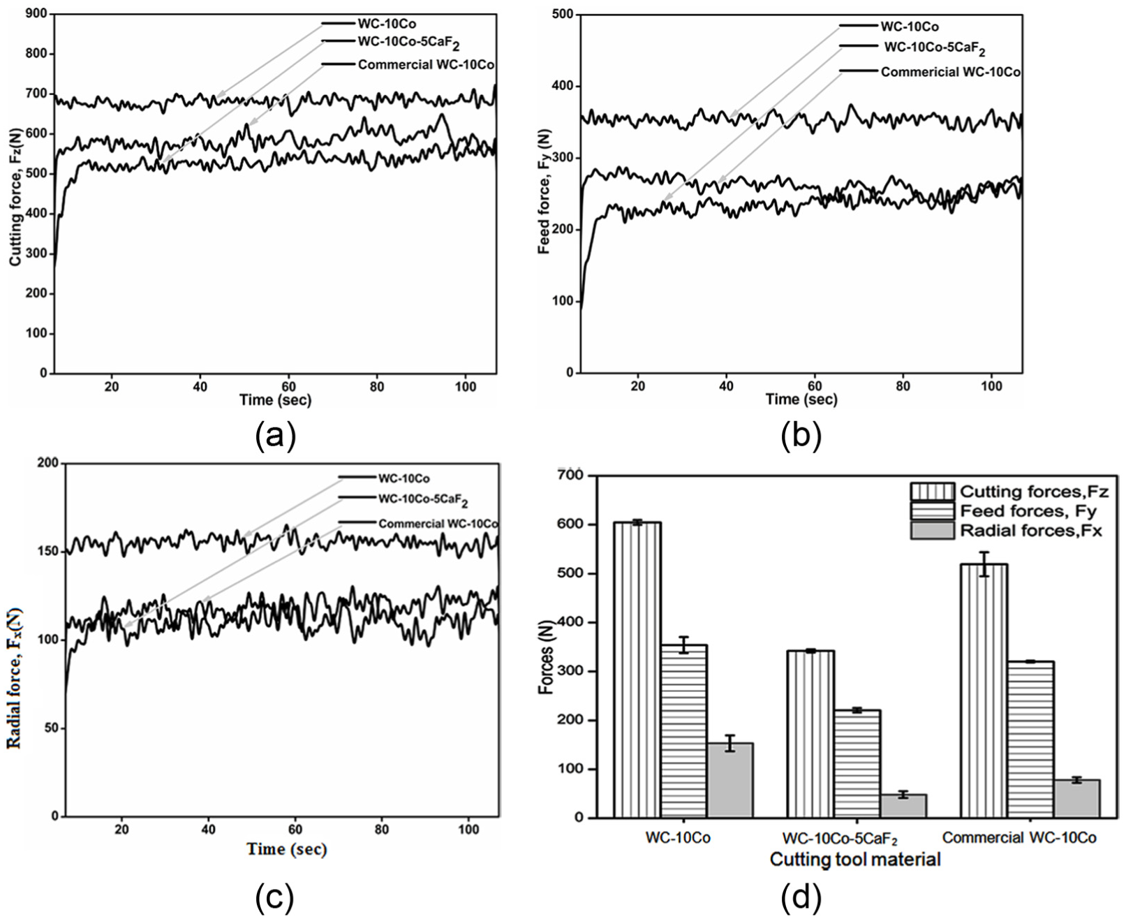
(a) Cutting force of the cutting tools at 80 m/min, (b) feed force of the cutting tools at 80 m/min, (c) radial force of the cutting tools at 80 m/min and (d) measured forces of the cutting tools at 100 m/min.
Frictional forces
The majority of heat generated during metal cutting is due to the friction between the cutting tool, workpiece and generated chip. By reducing the friction at the cutting tool–chip interface, the amount of heat generated during metal cutting can be significantly reduced. Many researchers1,3,5 have used the measured radial and tangential component of the cutting forces, and the following relationship 23 was applied to estimate the average friction coefficient at the tool–chip interface during machining

where β is the friction angle, νo is the rake angle, Fy is the radial thrust force and Fz is the primary cutting force. Using the measured radial force, cutting force and rake angle of the cutting tool, the friction coefficient between the tool and chip was computed, and the results are plotted in Figure 3. The friction coefficients at the tool–chip interface of WC-10Co, WC-10Co-5CF2 and commercial WC-10Co at 80 and 100 m/min are shown in Figure 3. At 80 m/min, the coefficient of friction between the chip and WC-10Co cutting tool was 0.7–0.8. However, the coefficient of friction between the chip and WC-10Co-5CF2 was only 0.4–0.5. The friction coefficient at the tool–chip interface decreased by 40%–50% due to the addition of solid lubricant CaF2 at cutting speeds of 80 or 100 m/min.
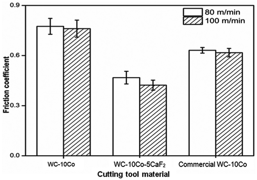
Predicted coefficient of friction between the tool and chip.
Deng et al. 3 observed that Al2O3/TiC without CaF2 exhibited a coefficient of friction of 0.6–0.7 during the machining of hardened steel (cutting speed = 60–80 m/min, depth of cut = 0.4 mm, feed rate = 0.1 mm/r), and the addition of CaF2 reduced the coefficient of friction by 15%–40%. Furthermore, Al2O3/TiC with CaF2 exhibited a 20% reduction in the friction coefficient when the cutting speed was increased from 60 to 80 m/min. In this investigation, the maximum decrease in the coefficient of friction was 20%, which was observed when the cutting speed was increased from 80 to 100 m/min. Deng et al. 5 observed a 24%–42% reduction in the friction coefficient when the TiB2 content was increased from 10% to 40%. The maximum reduction in the coefficient of friction was 30%, which was observed when the cutting speed increased from 50 to 200 m/min. Deng et al. 6 observed a 13%–27% reduction in the friction coefficient of textured and WS2-deposited cutting tools. When the cutting speed was increased from 50 to 250 m/min, textured and WS2-deposited cutting tools exhibited a 27% reduction in the friction coefficient.
Net average temperature at the tool–chip interface
Heat generated due to cutting significantly affects the cutting tool lifetime and the performance of the tool. Figure 4(a) shows the thermal image acquired while cutting steel with the WC-10Co-5CaF2 cutting tool at a speed of 80 m/min. The temperatures shown in the image are not the actual temperatures of the tool–chip interface; rather, these values represent the average net temperature of the cutting tool near the tool–chip interface, which indicates the relative amount of heat generated by the cutting tool. Figure 4(b) shows the average temperature of the cutting tool during the machining of steel at a cutting speed of 80 m/min. For all of the cutting tool materials, the mean cutting temperature gradually increased in the beginning of the machining process and then reached saturation. The mean cutting temperature of the commercial grade WC-10Co and developed WC-10Co reached approximately 200°C and 270°C, respectively. A reduction in 40%–50% was observed when cutting was carried out with the WC-10Co-5CaF2 tool at 80 m/min. The presence of solid lubricant CaF2 in the cutting tool rake and the flank surface significantly reduced the coefficient of friction at the tool–chip interface. The observed reduction in the friction coefficient reduced the resistance, which decreased the amount of heat generated during cutting.
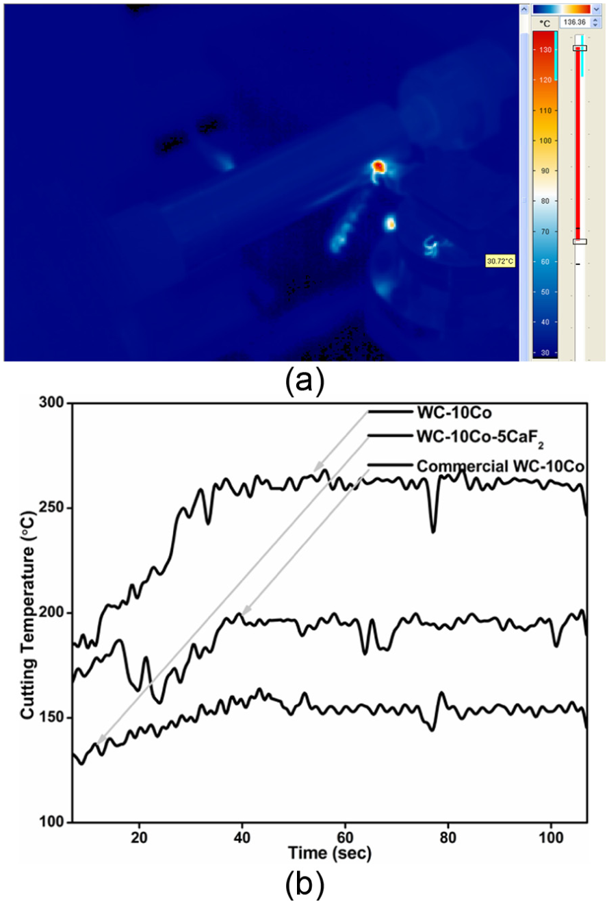
(a) Thermal images obtained during machining and (b) measured average temperature of the cutting tool at 80 m/min.
Deng et al. 6 measured the temperature of the tool–chip interface when machining with a commercial tool, textured tool and a textured tool filled with WS2 at a cutting speed of 50–250 m/min. A 15% reduction in the temperature was observed at 100 m/min with the textured tool filled with WS2. Xing et al. 1 observed a 10% reduction in temperature when textured and solid lubricant Al2O3/TiC cutting tools were employed at a cutting speed of 80 m/min. While evaluating the adhesive wear performance of the developed materials, the WC-10Co-5CaF2 cutting tool exhibited a 25%–35% decrease in the temperature of the tool–chip interface. 20
Cutting tool wear
The most significant problem associated with dry machining is the generation of excessive heat during cutting, which results in a shorter cutting tool lifetime. Steel workpieces were machined at 80 m/min using the three different cutting tools considered herein. The rake surface of the cutting tools was observed after 5 min of cutting. Figure 5(a) shows the rake surface of the developed WC-10Co cutting tool, which confirmed the occurrence of abrasive wear in the direction of chip flow. A close-up view of the rake surface (Figure 5(b) and (c)) confirmed the severe surface damage. Figure 5(d) shows the energy-dispersive X-ray spectroscopy (EDX) spectrum of the cutting tool without CaF2 which confirmed the constituents of the cutting tool tungsten (W), cobalt (Co) as well as adhesive material from the steel (Fe) workpiece.
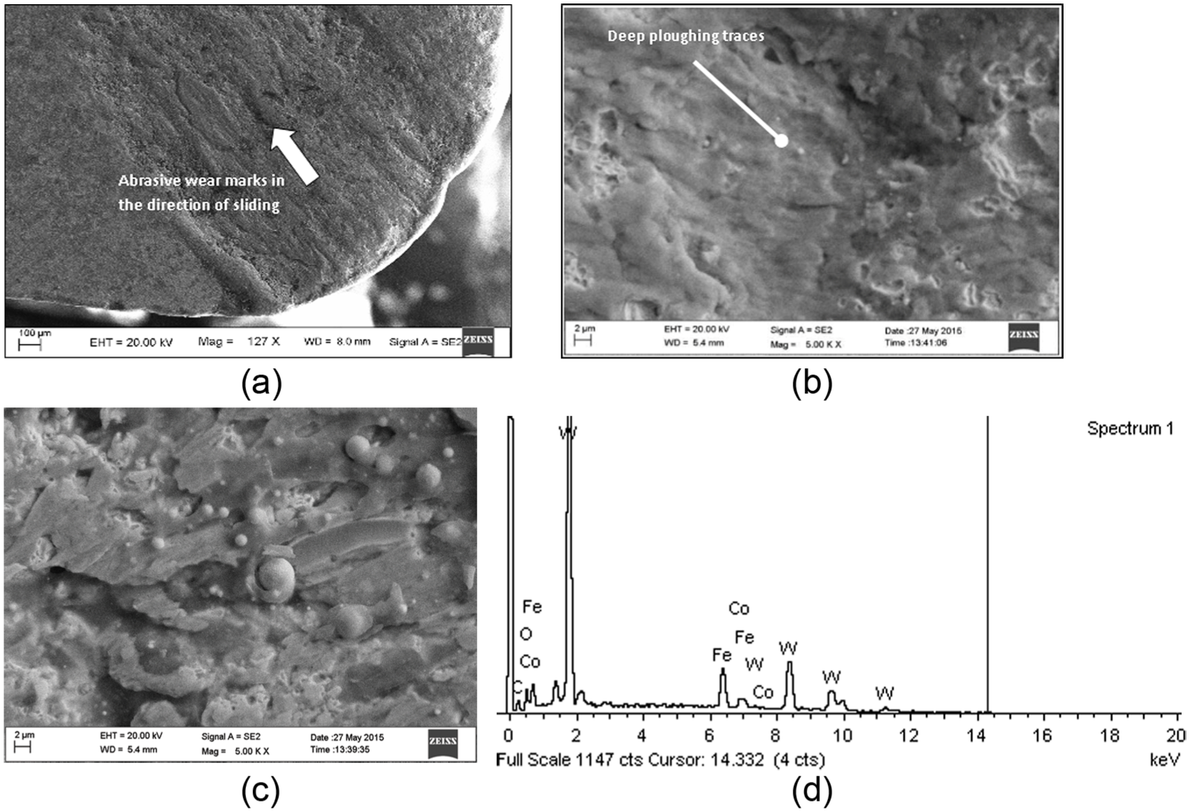
(a) Rake surface of the cutting tool without CaF2, showing severe wear, (b) close-up view of the rake surface of the cutting tool without CaF2, (c) close-up view of the rake surface of the cutting tool without CaF2 (another region) confirming severe surface damage and (d) EDX spectrum of the worn-out surface of the cutting tool without CaF2.
Figure 6(a) shows the rake surface of the WC-10Co-5CaF2 cutting tool after machining. The surface was indicative of mild wear and showed traces of adhesive wear. A close-up view of the rake surface (Figure 6(b)) revealed ridges parallel to the direction of chip flow, along with the dislodgement of carbide particles. Figure 6(c) shows the EDX spectrum of the cutting tool with CaF2 which confirmed the constituents of the cutting tool tungsten (W), cobalt (Co), calcium (Ca) as well as adhesive material from the steel (Fe) workpiece. The presence of Fe on the rake surface of the cutting tool confirmed the adhesion of the steel workpiece due to pressure and heat produced during cutting. The presence of calcium and fluoride also confirmed the existence of solid lubricant material during the cutting process and after sintering. Although excessive pressure and temperature were generated during cutting, the solid lubricant material endured on the rake surface, significantly reducing friction
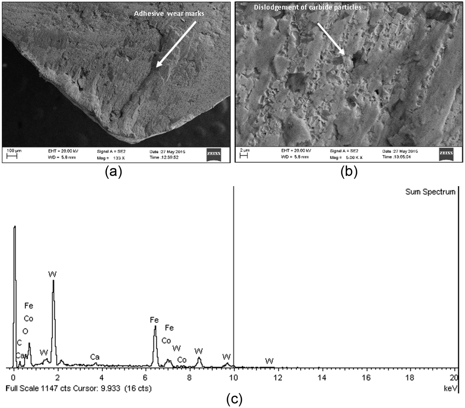
(a) Rake surface of the cutting tool containing CaF2, showing mild wear, (b) close-up view of the rake surface of the cutting tool containing CaF2 and (c) EDX spectrum of the worn-out surface of the cutting tool with CaF2.
Figure 7(a) shows the rake surface of the commercial WC-10Co tool, which showed traces of adhesive wear. A close-up view of the rake surface (Figure 7(b)) confirmed that localised plastic shearing occurred in the direction of chip flow. The elemental distribution along the rake surface of the commercial cutting tool was evaluated by EDX mapping (Figure 7(c)), which also confirmed the presence of Fe on the rake surface of the cutting tool.
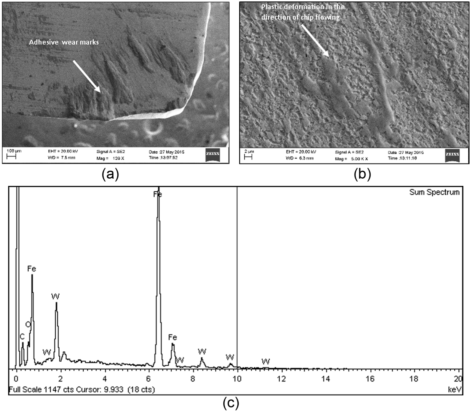
(a) Rake surface of the commercial cutting tool showing nominal wear, (b) close-up view of the rake surface of the commercial cutting tool and (c) EDX spectrum of the worn-out surface of the commercial cutting tool.
Using a toolmaker’s microscope, the amount of flank wear on the cutting tool was determined after 5 min of cutting, as shown in Figure 8. The measured flank wear of the WC-10Co-5CaF2 cutting tool at a cutting speed of 80 and 100 m/min revealed a 15%–18% reduction in temperature compared to WC-10Co. Xing et al. 1 investigated the performance of textured and solid lubricant Al2O3/TiC cutting tools and observed less crater wear at the flank surface of textured and solid lubricant burnished cutting tools compared to conventional cutting tools. The EDX surface of the solid lubricant cutting tool confirmed the presence of Mo and S. Xing et al. 2 developed coated and textured ceramic tools for the machining of hardened steel. Chipping and excessive abrasive marks were observed at the conventional cutting tool flank surface, whereas the cutting tool coated with WS2/Zr did not show any evidence of chipping. Furthermore, EDX mapping identified Zr and a small amount of W and S. Producing the required surface roughness on a workpiece is always a major concern in manufacturing. To understand the effects of cutting tool performance (especially on the surface roughness), workpieces were carefully prepared with initial roughness values of 2.8–3.2 µm. The final surface roughness of the workpiece machined by the WC-10Co cutting tool was in the range of 4.1–4.4 µm. The final surface roughness of the workpiece machined by the WC-10Co-5CaF2 cutting tool ranged from 3.4 to 3.8 µm. The final surface roughness of the workpiece machined by the commercial WC-10Co cutting tool was in the range of 3.6–4.0 µm.
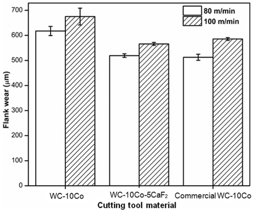
Measured flank wear of the cutting tool.
To understand the mechanism of metal removal, machined surfaces were observed using an optical microscope. Figure 9 displays the machined surface of WC-10-5 CaF2, where feed marks were clearly detected; however, the machined surfaces of all of the considered cutting tools were nearly identical. Figures 10 and 11 show the machined surfaces of WC-10Co and WC-10Co-5CaF2, which were observed using a non-contact three-dimensional profiler. Less resistance towards metal removal was exhibited by the workpiece while machining with the WC-10Co-5CaF2 cutting tool, as confirmed by the measured cutting force (Figure 2(a)). The shear angle determines the mechanism of material removal, and larger shear angles are associated with low cutting forces. Because the resistance was low, the material was removed uniformly, and the feed marks edges were well defined. Figure 10 shows the removal of non-uniform material during machining with WC-10Co. The results shown in Figure 11 indicated that material removal was uniform when machining was performed with WC-10Co-5CaF2.
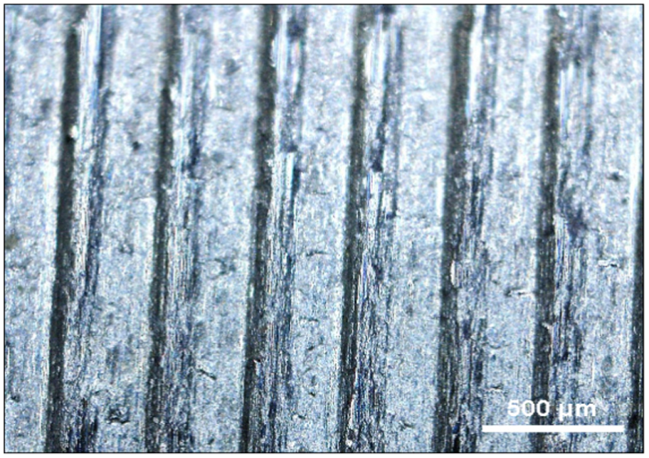
Machined surface of WC-10Co-5CaF2 (80 m/min), observed by the USB microscope.
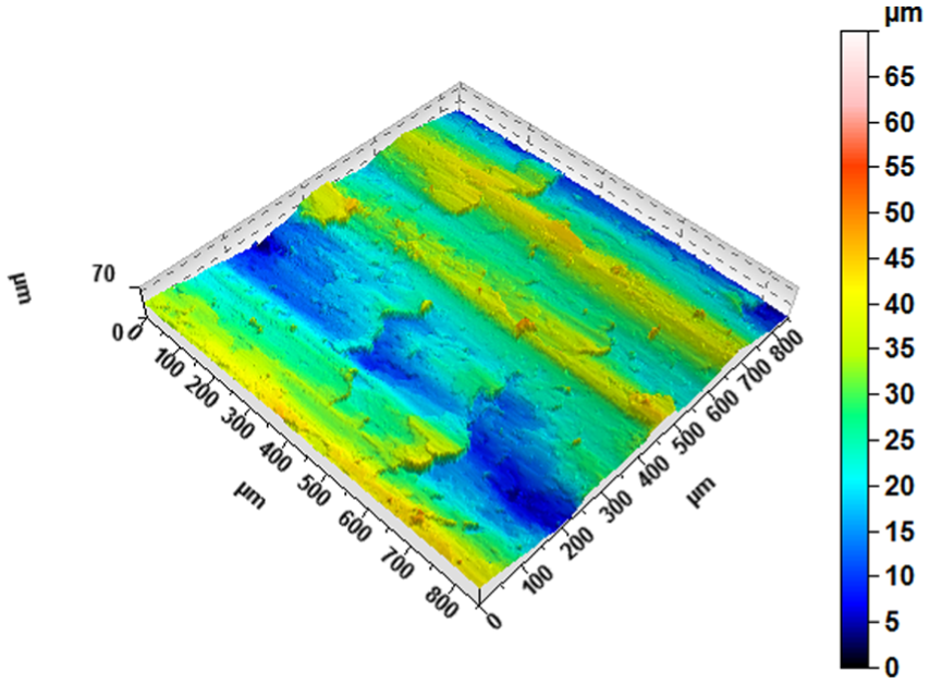
Machined surface of WC-10Co (80 m/min), observed by the non-contact three-dimensional profiler.
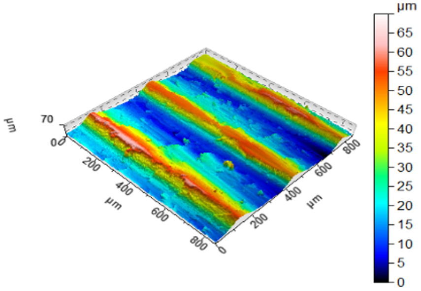
Machined surface of WC-10Co-5CaF2 (80 m/min), observed under the non-contact three-dimensional profiler.
Chip morphology
The frictional characteristics at the tool–chip interface were identified by the morphology of the machining chips. Because there was less friction at the tool–chip interface, contributes to generate lower temperatures were observed during cutting, which allowed the chip to become less ductile and promoted chip curling. Thus, curlier chips were indicative of low amounts of friction between the chip and cutting tool.7,23 Figure 12 shows the chips generated during workpiece machining with the considered cutting tool materials. Among the cutting tools, the WC-10Co-5CaF2 cutting tool generated chips with smaller radii. Figure 13(a) and (b) shows the backside of chips obtained from WC-10Co and WC-10Co-5CaF2 cutting tools, respectively. Chips produced by the WC-10Co-5CaF2 cutting tool were curlier compared to those produced by the WC-10Co cutting tool, and less friction (Figure 3) and lower temperatures (Figure 4(b)) were generated by the WC-10Co-5CaF2 cutting tool. Biksa et al. 24 also observed curlier chips while investigating the wear behaviour of cemented carbide tools with multilayered nanocoatings. Specifically, multilayered AlTiN/MoN-coated cutting tools generated less friction between the tool and the chip; hence, the chips were curlier compared to mono-layered AlTiN. Liang et al. 25 investigated the effect of heat pipe cooling on chip morphology, and cutters with heat pipes produced chips with smaller helical radii compared to those without heat pipes.
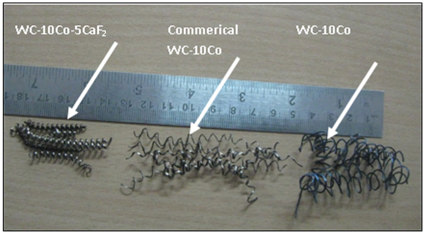
Chips generated by the three cutting tools.
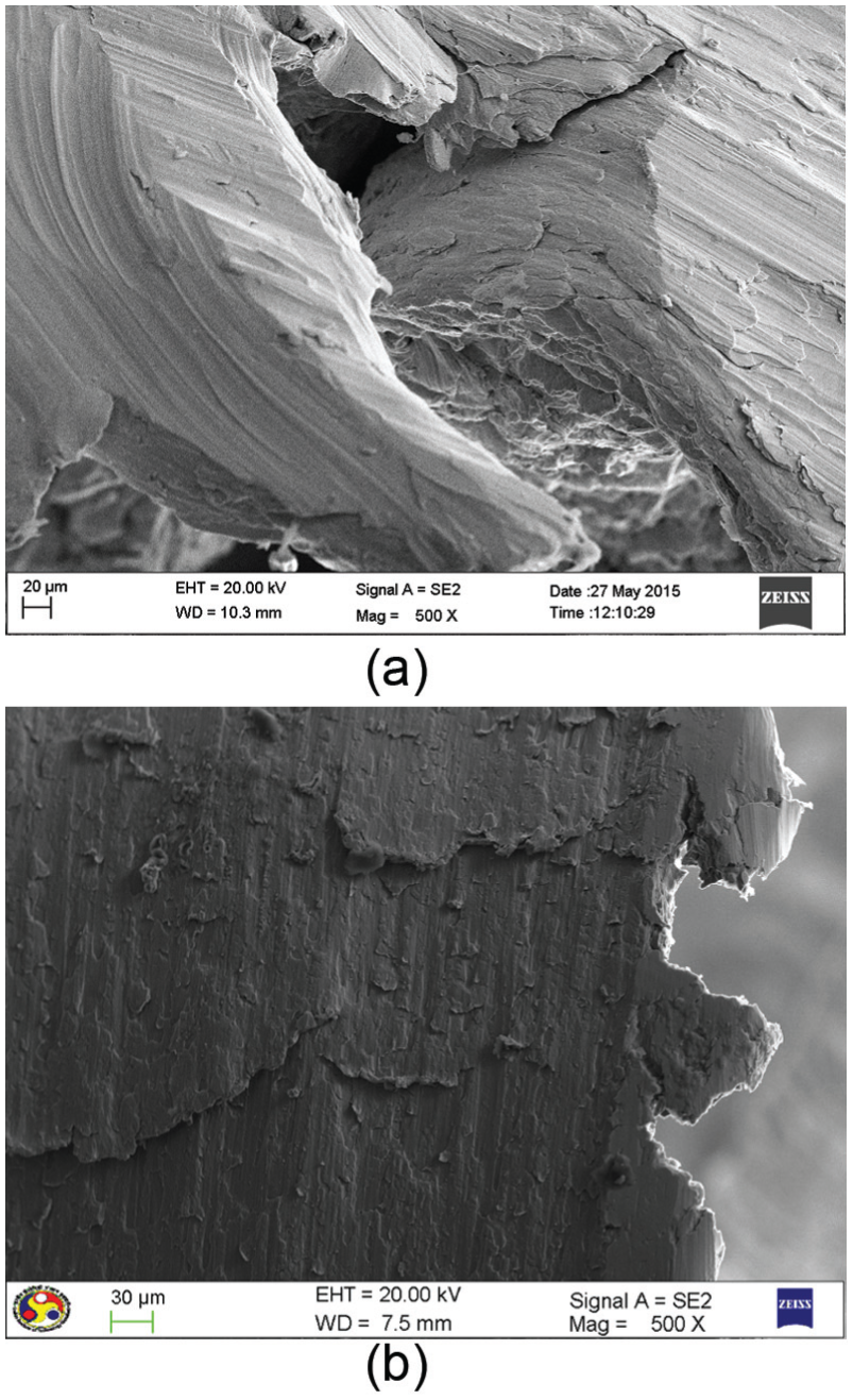
Backside of chips produced by (a) the WC-10Co cutting tool and (b) the WC-10Co-5CaF2 cutting tool.
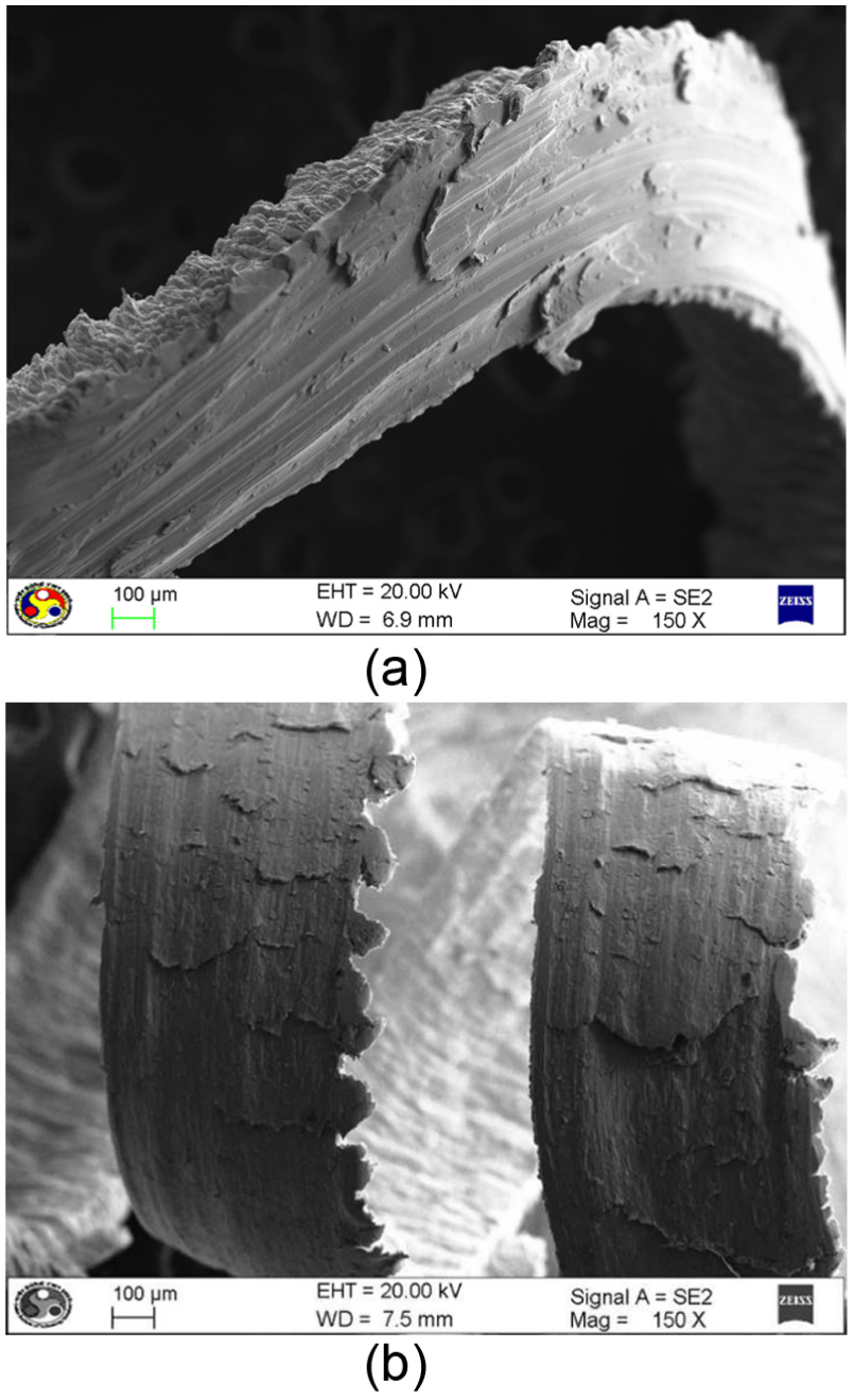
During machining, serrated chip flow occurs due to the breakage of steady chip flow, which deteriorates the cutting tool lifetime and the finish of the workpiece surface. 7 Figure 14(a) and (b) showed that serration occurred on the chip edge during machining with WC-10Co and WC-10Co-5CaF2 cutting tools, respectively. The WC-10Co-5CaF2 cutting tool generated serrated chips with smaller saw tooth sizes than that of the WC-10Co cutting tool, as confirmed by the improved workpiece surface finish (less roughness) of the WC-10Co-5CaF2 cutting tool. Bermingham et al. 26 also observed small serrated chips while investigating the application of liquid nitrogen cooling. Su et al. 27 found that the minimum surface roughness occurred at the beginning of the chip serration stage, and that the maximum surface roughness occurred at the middle of the serration stage.
Serrated chip edge produced by (a) the WC-10Co cutting tool and (b) the WC-5% CaF2 cutting tool.
Figure 15 shows the front/free surface of the chip produced by the WC-10Co-5CaF2 cutting tool. The front surface contained uniformly spaced lamellae, which extended across the width of the chips in the direction of chip flow. The presence of lamellae on the free surface of the chips confirmed the dominance of shearing over ploughing and wear with all of the considered cutting tools. 28 Figure 16 shows the EDS spectrum of the chip produced by the WC-10Co-5CaF2 cutting tool, which confirmed the presence of calcium in the chip. During cutting, due to excessive pressure and temperature, part of the solid lubricant material present in the cutting tool material was transferred to the chip.
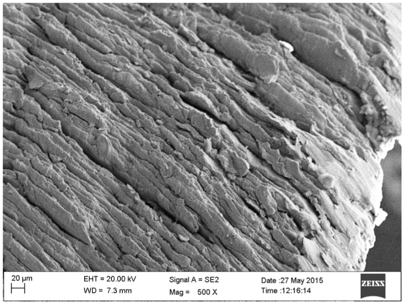
Front surface of chips produced by the WC-10Co-5CaF2 cutting tool.
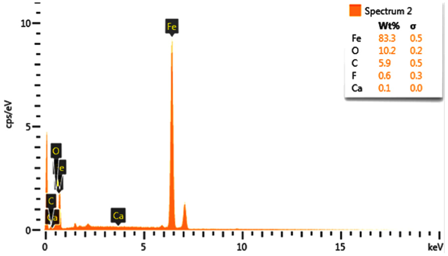
EDX spectrum of chips produced by the WC-10Co-5CaF cutting tool.
Conclusion
In this work, the performance of an in-house-developed tungsten carbide cutting tool with and without calcium fluoride was determined. Steel was machined in a lathe at two different cutting speeds, and the following conclusions were derived from the cutting experiments:
The in-house developed WC-10Co-5CaF2 cutting tool exhibited less force (20%–40%) in all three directions (tangential, axial and radial) due to the presence of a solid lubricant on the rake and flank surfaces.
The in-house-developed WC-10Co and commercial WC-10Co cutting tool generated higher cutting temperatures (40%–50%) compared to the developed WC-10Co-5CaF2 cutting tool.
The machined surface morphology results confirmed that the resistance was lower when machining was performed with the WC-10Co-5CaF2 cutting tool. The roughness of the generated surface confirmed the role of the solid lubricant.
The chip generated from the WC-10C-5CaF2 cutting tool exhibited greater curling and smaller saw tooth sizes. The smaller saw tooth sizes indicated that the surface finish of the workpiece improved, and the observed increase in chip curling suggested that the cutting temperature was lower.
The chip generated from the WC-10C-5CaF2 cutting tool revealed that traces of calcium and fluoride were present, confirming the lubrication effect during machining.
Footnotes
Acknowledgements
The authors also wish to thank DST FIST-2008 and Centre for Instrument Facility, IIT Guwahati, for their kind assistance.
Declaration of conflicting interests
The author(s) declared no potential conflicts of interest with respect to the research, authorship and/or publication of this article.
Funding
The author(s) disclosed receipt of the following financial support for the research, authorship, and/or publication of this article: This project is funded by Aerospace Manufacturing and Value Engineering Panel of ARDB, India (DARO/08/1103/M/I).