
Abstract
The ultrasonic impact treatment process is widely used to improve the fatigue life of the weldments by inducing compressive residual stresses at the sub-surface. The purpose of the article is to conduct the dynamic elastic–plastic finite element analysis of multiple impacts on 5A06 aluminum alloy with different controlled parameters. The numerical model was validated by pin drop test. The changes in penetration depth, maximum compressive residual stress, and surface residual stress were obtained by analyzing the residual stress field and equivalent plastic strain. The effect of impact times, impact velocities, pin shapes, and impact angles on the residual stress was investigated so that the ultrasonic impact treatment parameters could be controlled to obtain expected residual stress distributions.
Keywords
Introduction
Ultrasonic impact treatment (UIT) is a surface cold-working process which is widely used to produce surface nanocrystalline and improve the hardness and fatigue life of the metallic materials. The technology is a further development of the shot peening and hammer peening, which uses pins repeatedly impacting on the component by high-power energy. It was developed at the Northern Scientific and Technological Foundation in Severodvinsk, Russia, associated with Paton Welding Institute in Kiev, Ukraine, 1 for the shipbuilding industry. 2 Compared with other processes, such as traditional shot peening, 3 ultrasonic shot peening, 4 laser shot peening, 5 and high pressure waterjet peening, 6 the UIT device is more controllable and convenient, and it can induce lower surface roughness and deeper compressive residual stress layer. These characteristics promote the development of the UIT technology in the aerospace, automotive, and power industries. Especially in the welding industry, by impacting many times the weld bead and the base metals,7,8 it will form a groove between the weld bead and the base material, in which the compressive residual stress and the refined grains9,10 can be obtained to improve the fatigue life of the welded structures. The residual stress is usually measured by experiment at present. However, the high cost and poor efficiency make experimental method difficult to be applied widely. With the development of the finite element (FE) technology, it provides the possibility to predict material status without large physical tests.
Due to the complexity of the UIT process, the study of its simulation is rarely reported. Similar to the traditional shot peening process, the UIT process is also an impact process. The UIT model could be established by improving the traditional shot peening model. The shot peening process has already been simulated by many FE models, such as two-dimensional (2D) axisymmetric models,11,12 three-dimensional (3D) symmetric models,12–14 single/multiple impacts models,12–16 and angled-impacts models. 17 All these models were developed to fit the elastic–plastic deformation and the residual stress profile. Among the models above, 2D axisymmetric models have the longest history. Johnson 18 initialized using a pseudo-dynamic approach to develop a dynamic impact model with a single shot, in which the inertial properties were considered. The relationships between the depth of plastic zone and the properties of the shot, such as radius, mass, and velocity, were obtained. With the development of computational capabilities, shot peening numerical models have been further improved. Edberg et al. 19 were the first to use commercial FE program to analyze the shot peening process. Al-Hassani et al. 20 simulated the process of single and multiple shots impact and analyzed the situation of single shot impacting with an incident angle. Deslaef et al. 21 and Rouhaud and Deslaef 22 examined the effects of rigid/deformable shot on residual stress. Frija et al. 23 used an integrated damage law to obtain the residual stress, the plastic deformation profiles, and the surface damages. Dai et al. 24 developed a 3D FE model to discuss the final surface roughness, the processing time, the microstructure transformation, and changes in properties during the nanocrystallization and hardening process. Schwarzer et al. 25 used infinite elements to avoid strain wave reflections. Guagliano 26 discussed the relationships between the key parameters, such as shot velocity, shot size, and Almen intensity. Wang et al. 27 obtained the residual stress distribution by applying different temperature values to sample points through the thickness of the shell element.
In these models, the common characteristic is that the shot size is small and the contact velocity is high, which is not suitable for the UIT technology. Besides these, other characteristics, such as the high contact frequency, the high surface coverage, and the multi pin shape, also indicate that the shot peen models cannot be used as the UIT model directly. The article aims at developing 3D FE models of the UIT process with different controlled parameters to predict the distributions of the residual stresses and the deformations by improving the shot peening models. An impact process will be first simulated to obtain the contact time between the pin and the target, which is used to estimate the time interval between the two consecutive impacts. The effect of impact times, impact velocities, and pin shapes on the residual stress profile will be discussed in detail. Also the multiple impacts on the target with different impact angles will be simulated and investigated.
FE modeling
The configuration of TJU-HJ-III style UIT device is shown in Figure 1. It consists of two parts: ultrasonic wave generator and UIT operator; the latter part includes energy transducer, ultrasonic horn, and peening pins. The center frequency of output ultrasonic vibration is 17 kHz and the amplitude range is 0–25 µm, while the impact frequency between the pins and the target is much lower than 17 kHz.
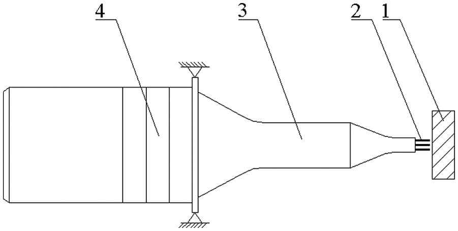
Configuration of UIT device.
For simplifying the computation process, the following assumptions were set: the time intervals between the consecutive impacts are invariant and the process of one pin impacting many times on the target is assumed as multiple pins arranged in a preprogrammed array impacting the target.
Based on the shot peening models, the article developed 3D FE models to investigate the effect of key parameters on the residual stress using the commercial FE code Abaqus/Explict 6.10. The models for the process with one pin impacting the target one time (single-impact model) and multiple times (multi-impact model) were developed, as shown in Figure 2. Single-impact model is used to be validated by the experimental results. In the multi-impact model, 10 pins impacting the target at the same position are used to replace the process of one pin repeatedly impacting the target 10 times. Multi-impact model is employed to obtain relationships between the controlled parameters and the residual stress distributions.
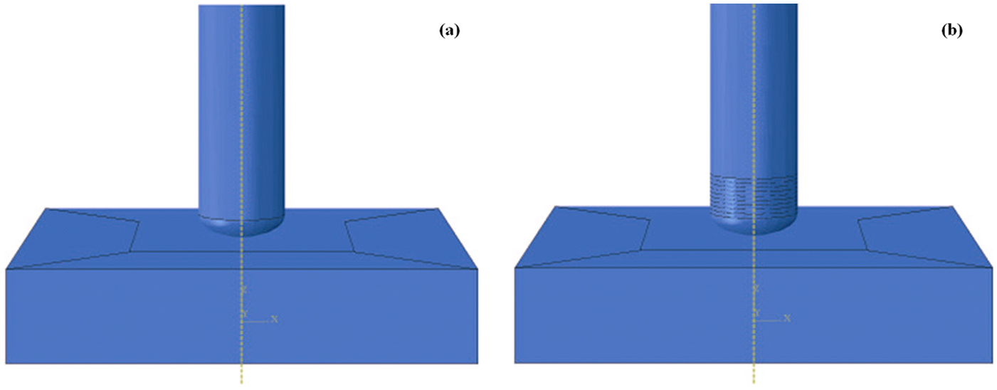
Finite element models for (a) single-impact and (b) multiple impacts.
The specimens are plates with geometry of 20 mm × 20 mm × 4 mm. The pin size is shown in Figure 3(a), where the diameter ϕ = 4 mm, the length L = 30 mm, the impact zone is semi-ellipsoid, and the semi-axis b = 1 mm. In the second model, the arrangement of the pins is shown in Figure 3(b). The interval between two consecutive impacts D is considered to be kept constant.
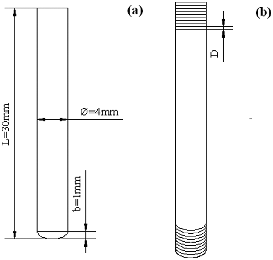
Size and arrangement of the pins: (a) single-impact model and (b) multi-impact model.
In the UIT process, the pin endures much less deformation than the specimen, so the pin is defined as rigid body and the specimen is defined as elastic–plastic body. The pin is meshed with C3D4 elements. The specimen is meshed with reduced integration (C3D8R) elements, which is shown in Figure 4, the bottom of it is restrained against all displacements. The mesh near the contact region is refined for numerical accuracy and the mesh for the other region is coarse for saving computation time.
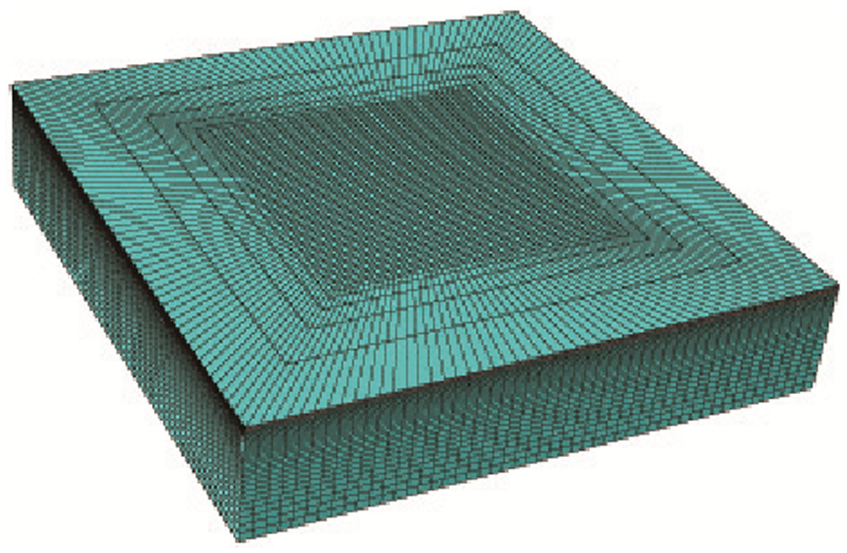
The cell of the specimen (element: 105000; node: 111631).
The impact velocity of the pins is kept constant to simplify the simulation. Considering the capacity of the UIT machine, the initial velocity of the pin is 2 m/s. In the multi-impact model, the interval between two consecutive impacts is also kept constant, and the “distance” (namely, the height difference) between the two consecutive pins is obtained from the result of the single-impact model. The computation process will be explained in section “Result of single-impact model.” In the multi-impact model, the valid “pin number” (namely, impact times) which plays the most important function in the impact process is also determined.
In the impact process, the friction coefficient between the pin and the specimen is set to be 0.25. Due to the large deformation of elastic–plastic material, material model employed Johnson–Cook model, which can consider the strain rate on material hardening effectively, as expressed by
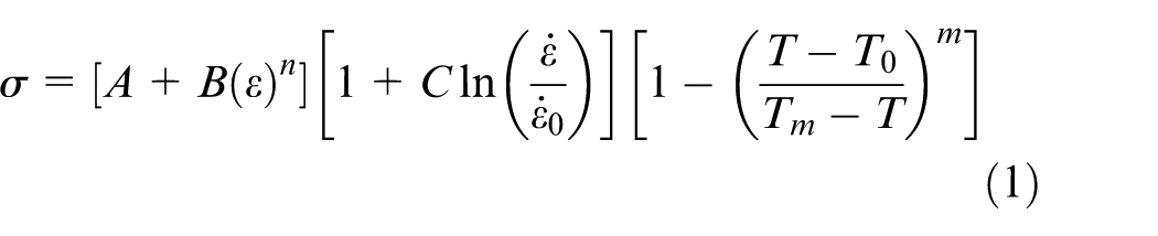
where
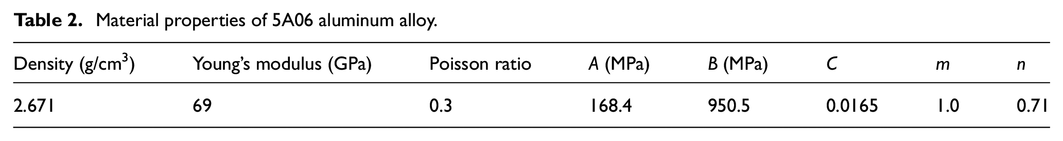
The material for the specimen in the models is 5A06 aluminum alloy, and the chemical composition of the 5A06 aluminum alloy is given in Table 1. The material properties and the Johnson–Cook properties 28 are given in Table 2.
Chemical composition of 5A06 aluminum alloy (Wt %).
Material properties of 5A06 aluminum alloy.
Model validation
Due to the high impact frequency in the UIT process, the residual stress distribution by only one impact cannot be obtained by the experiment. Based on the Hertz contact theory, Miao et al.
29
indicated that the maximum plastic radius
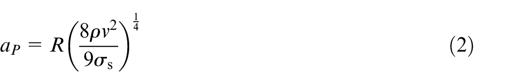
where
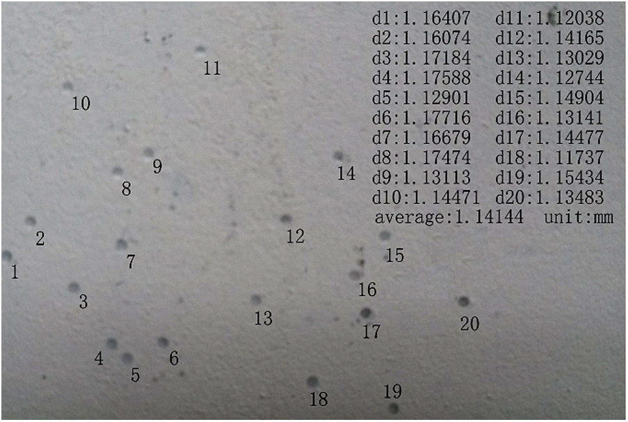
The indentations produced on the target.
The indentation shapes in the surface zone.
Results and discussions
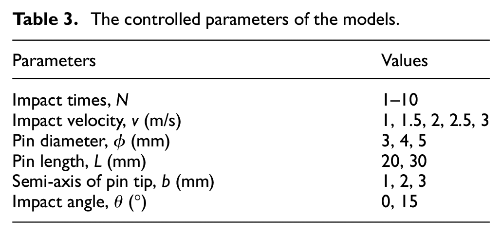
The effects of impact times, impact velocities, pin diameters, pin lengths, pin shapes, and impact angles on the residual stress distributions were investigated. Table 3 gives the simulations matrix. The residual stress with depth along the vertical axis through the center point of the impact zone is schematically shown in Figure 7, where
The controlled parameters of the models.
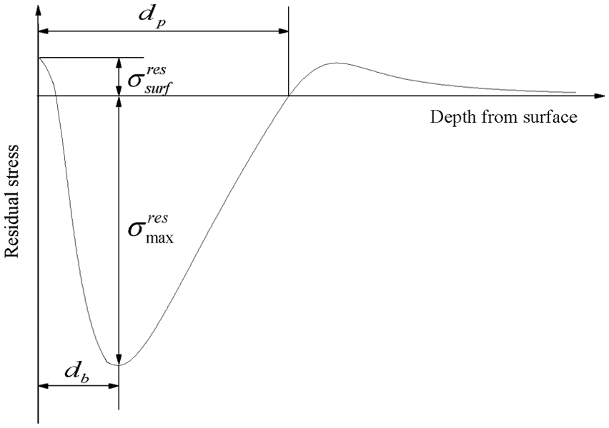
Important characteristics of typical compressive residual stress profile.
Influence of the impact times
Result of single-impact model
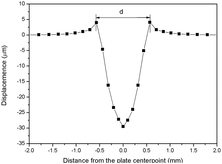
The contact time between the pin and the target was investigated in the single-impact model. The contact time is substituted by the deformation time of specimen. Figure 8 shows the deformation of the center point on the top surface. The jump of the curve shows the process of elastic deformation, elastic–plastic deformation, and the elastic rebound of the specimen. From Figure 8, the contact time is about 0.04 ms.
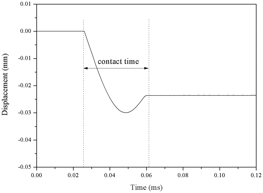
Variation of deformation of midpoint of target top surface with time: v = 2 m/s, ϕ = 4 mm, b = 1 mm, and L = 30 mm.
Since the impact frequency between the pin and the target is about 100 Hz, the time interval between two pins is about 10 ms. Taking 2 m/s as the pin velocity, the “distance” between the consecutive pins is 20 mm. However, as the computation time interval is larger than the contact time and the process before the contact is no need to simulate, the distance between every two pins was designed to D = 0.2 mm for the following models.
Result of multi-impact model
Due to the high coverage feature of UIT, a new model was established to simulate the multiple impact process. The model is shown in Figure 2(b). The residual stress profiles for different impact times are shown in Figure 9.
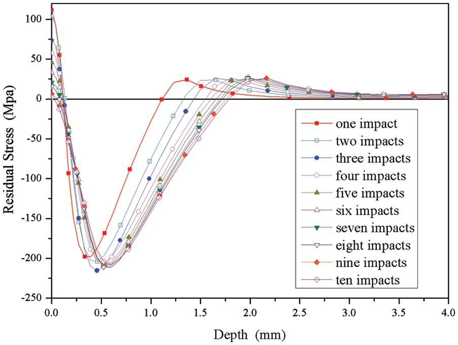
Effect of impact times upon residual stress distribution along the specimen center line: v = 2 m/s, ϕ = 4 mm, b = 1 mm, and L = 30 mm.
In the impact process, the kinetic energy of pin is converted to elastic and plastic energy in the target. As is known, increasing impact times also increases plastic energy in the target, hence the maximum residual stress increases. But the stress–strain curve is non-linear. The deeper the plastic zone is produced, the more the energy should be provided. With the increase in the plastic zone, it needs to cost more energy to produce further deformation. After the third impacts, the impacted surface has been fully work-hardened. Further impacts cannot increase the maximum compress residual stress but the energy could be transmitted to the deeper zone of the specimen, which leads to the increase in the penetration depth. Meanwhile, the force of the center part of the plastic zone, induced by the surrounding zone, could be reduced by the increase in the plastic zone, so the maximum compress residual stress declines after the third impact. According to the Figure 9, first four impacts almost took up most of the increase for
Due to the expanding of the top surface,
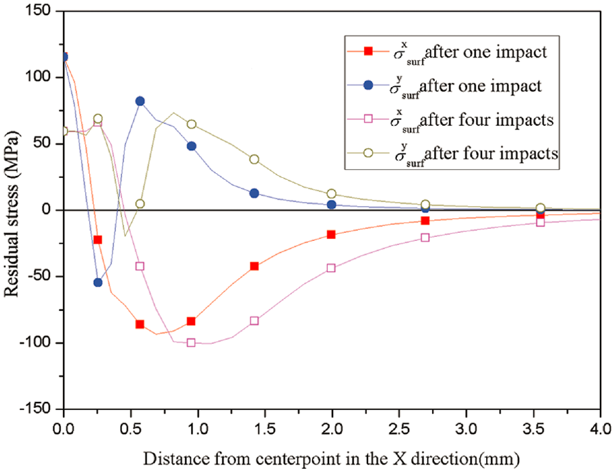
The distributions of the surface residual stress: v = 2 m/s, ϕ = 4 mm, b = 1 mm, and L = 30 mm.
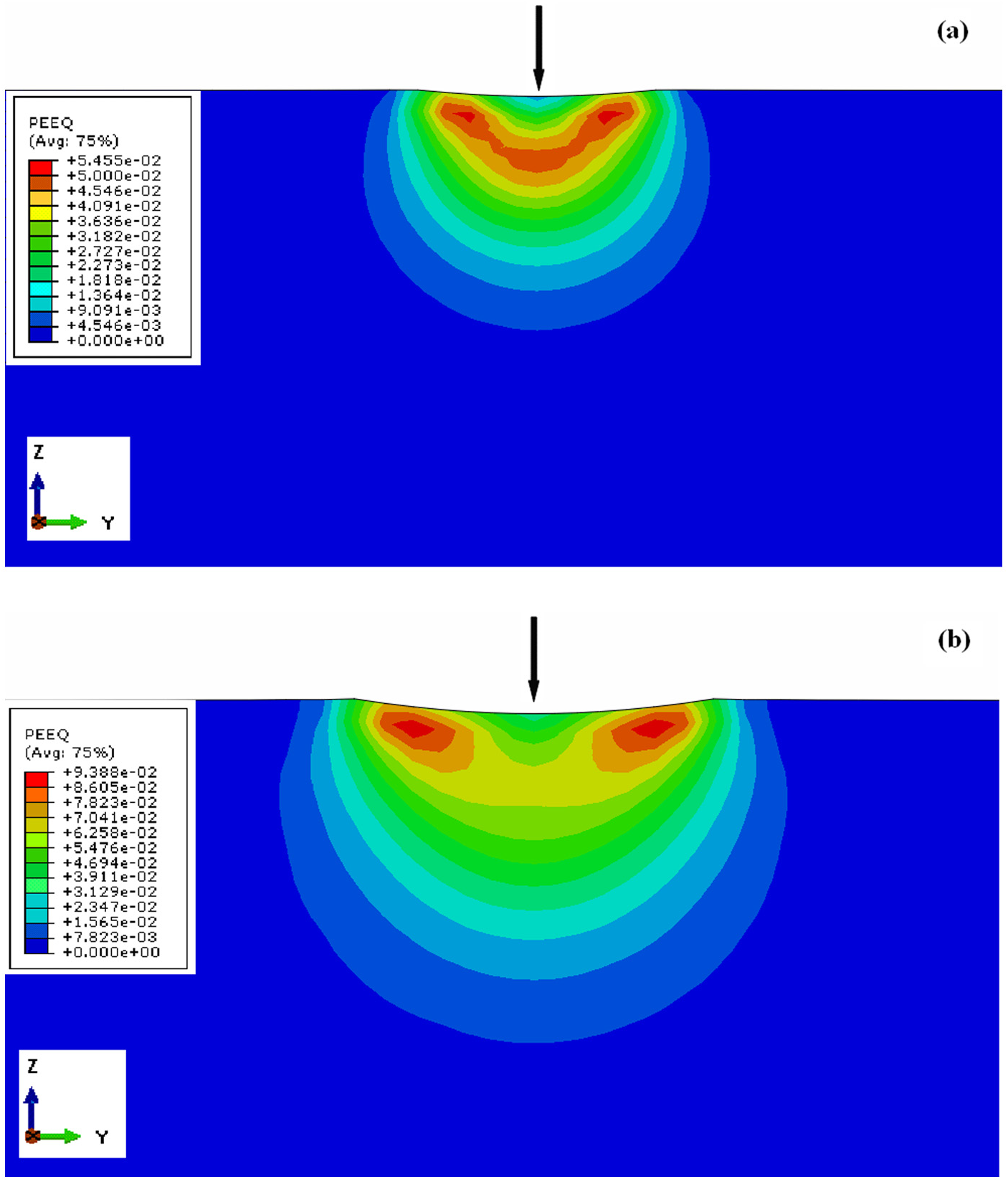
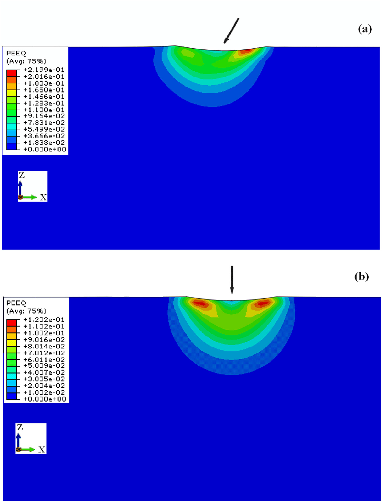
Equivalent plastic strain (PEEQ) contour for (a) single-impact model and (b) 10-impact model (cutting in the Y-Z plane). The center of the impact zone is marked with the arrow indicated.
Influence of the initial velocity
In the actual UIT experiment, the impact velocity of the pin could be set by adjusting the device amplitude. In the multi-impact UIT model, different initial impact velocities (1, 1.5, 2, 2.5, and 3 m/s) are employed to analyze the residual stress distributions, and the residual stress profiles are shown in Figure 12. Due to the increased kinetic energy of the pin,
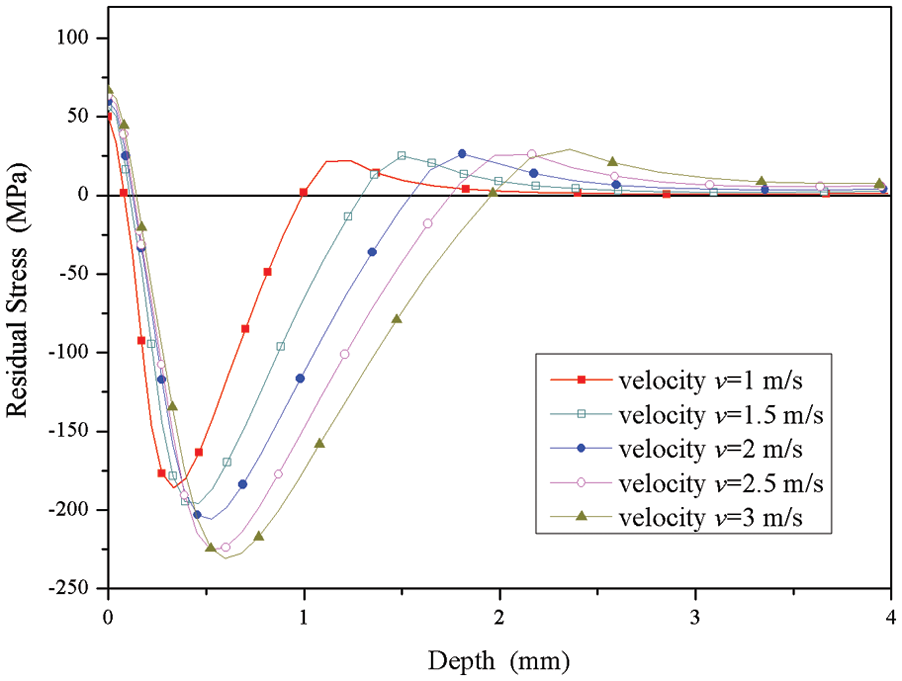
Effect of initial velocity upon residual stress distribution along the center line after four impacts: ϕ = 4 mm, b = 1 mm, and L = 30 mm.
Influence of the pin size
Influence of the pin diameters
In the multi-impact UIT model, three different diameters are chosen; the initial velocity of the pins and the boundary conditions of the specimen are the same as the previous model. The diameters of the pins are 3, 4, and 5 mm, and the curvature of the impact surfaces is invariant.The residual stress against the pin diameters is plotted in Figure 13. It shows that
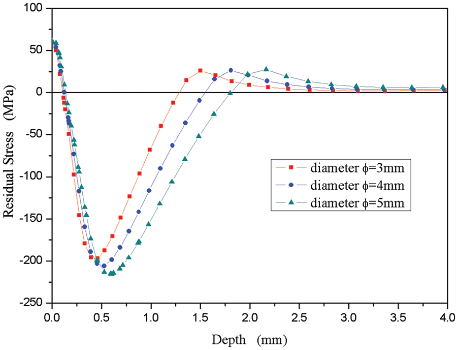
Effect of pin diameter upon residual stress distribution along the center line after four impacts: v = 2 m/s, b = 1 mm, and L = 30 mm.
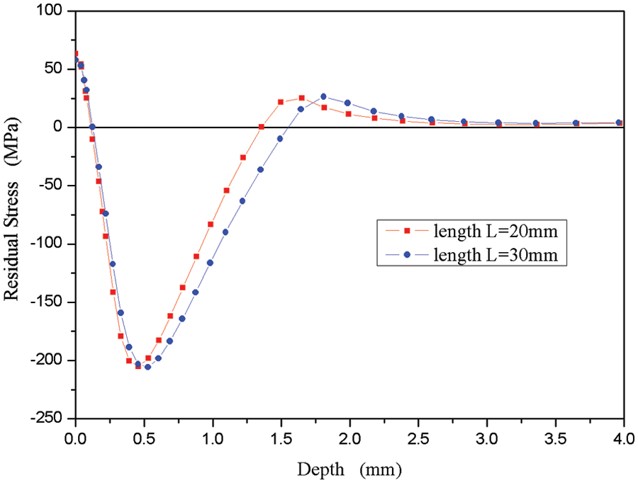
Influence of the pin length
The residual stress distributions with two different pin lengths (20 and 30 mm) are shown in Figure 14. With the increase in the pin length from 20 to 30 mm,
Effect of pin length upon residual stress distribution along the center line after four impacts: v = 2 m/s, ϕ = 4 mm, and b = 1 mm.
Influence of the pin tip
In the UIT process, many kinds of pin tips could be chosen, so the effect of the pin tips upon the residual stress is considered. Figure 15 shows the effect of pins (which have the same mass) with three different tip shapes, namely, three semi-axis bs (1, 2, and 3 mm) upon the residual stress. The increase in the semi-axis resulted in an increase in
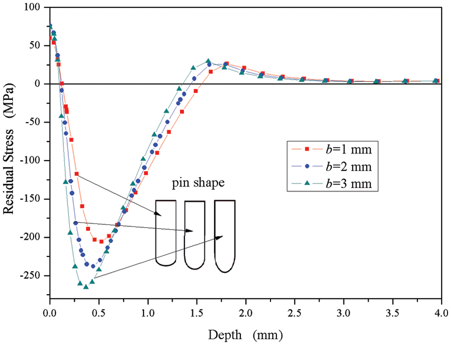
Effect of pin shape upon residual stress distribution along the center line after four impacts: v = 2 m/s, ϕ = 4 mm, and L = 30 mm.
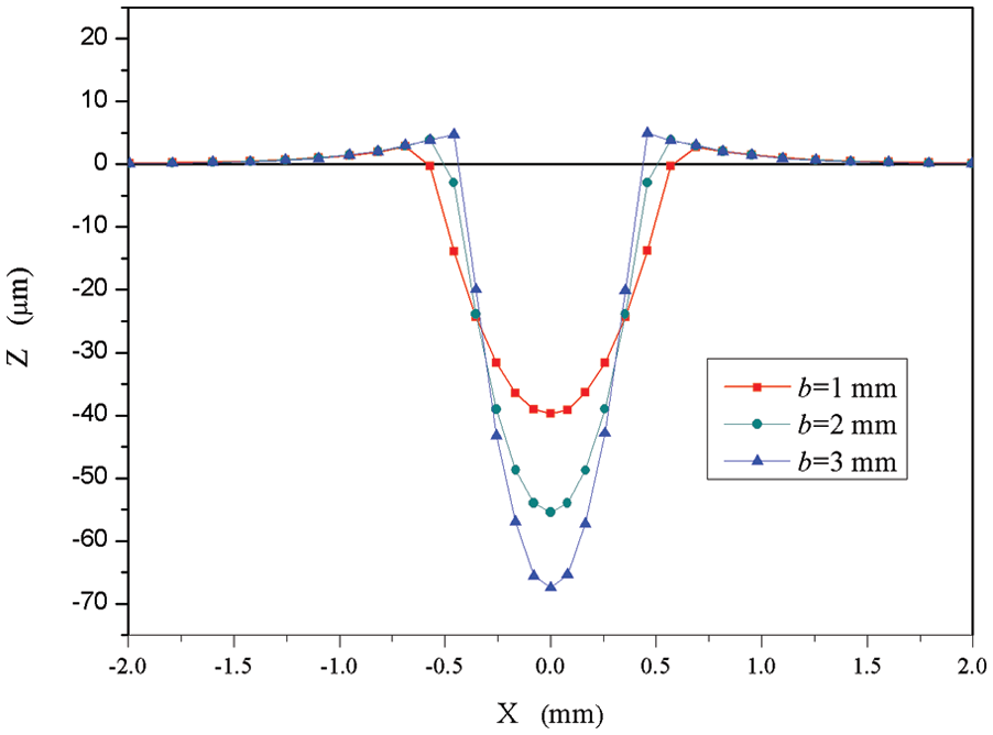
The indentation shapes in the surface zone with different bs after four impacts: v = 2 m/s, ϕ = 4 mm, and L = 30 mm.
Influence of the impact angle
In the actual UIT process, the pin is not always normal to the specimen surface. Under special conditions, an angle is specified between the pin and the target, as shown in Figure 17. In the multi-impact UIT model, the impact process with pins impacting the target at different incident angles (
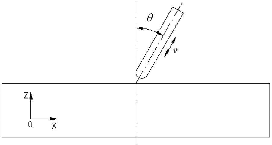
The schematic diagram of inclined impact process.
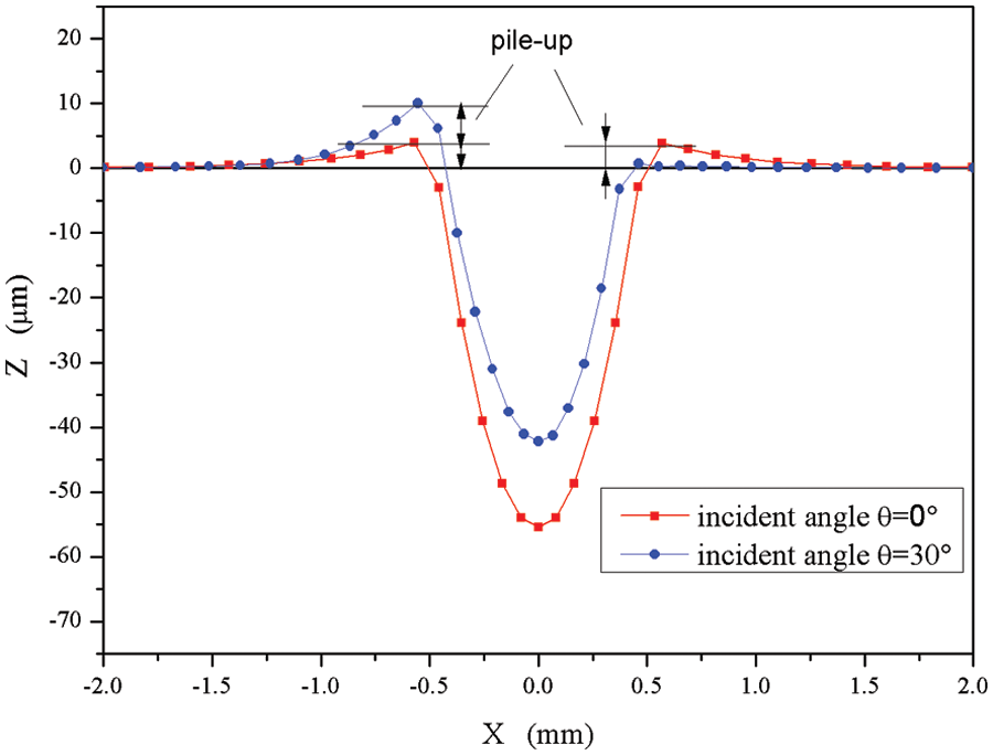
The indentation shapes in the surface zone with different impact angles: v = 2 m/s, ϕ = 4 mm, and L = 30 mm.
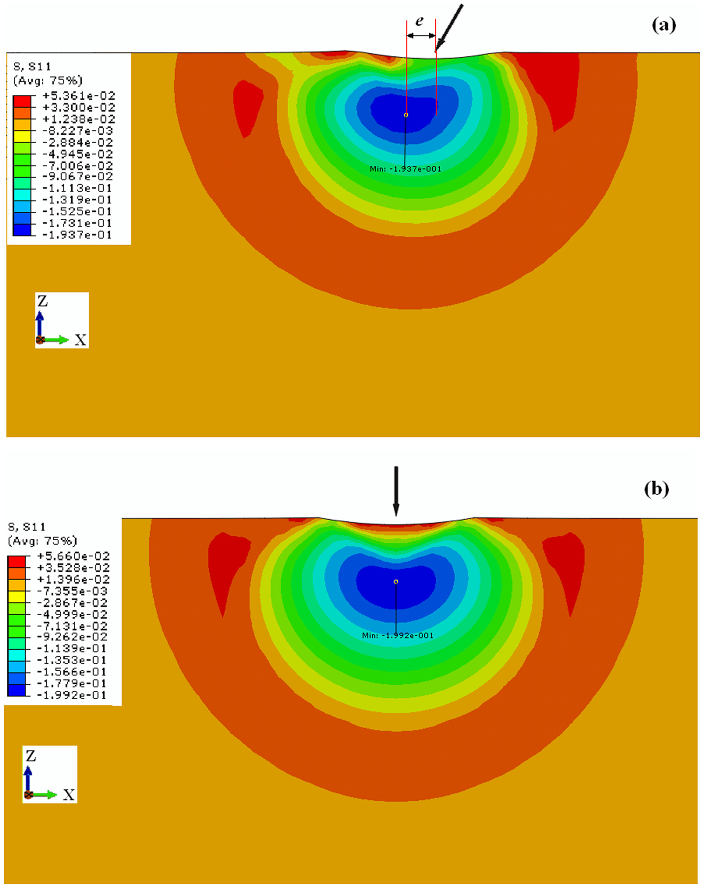
The residual stress contour after (a) 15° oblique impacts and (b) 0° normal impacts (cutting in the X–Z plane). The center of the impact zone is marked with the arrow indicated. v = 2 m/s; ϕ = 4 mm; L = 30 mm.
Equivalent plastic strain (PEEQ) contour after (a) 15° oblique impacts and (b) 0° normal impacts (cutting in the X–Z plane). The center of the impact zone is marked with the arrow indicated. v = 2 m/s, ϕ = 4 mm, and L = 30 mm.
Conclusion
The 3D explicit models for UIT process with single-impact or multiple-impacts on 5A06 aluminum alloy were developed using ABAQUS/Explicit, which were validated by pin drop test. The simulation results of UIT process showed,
Increase in impact times induces the increase in the depth and magnitude of the compressive residual stress and the decrease in the surface tensile residual stress. The maximum compress residual stress reaches its maximum after the third impact and further increase in impact times offers less effect on it.
Increase in initial velocity, pin diameter, pin length, and pin semi-axis significant increases the penetration depth, the maximum residual stress depth, and the maximum compressive residual stress but the trends are non-linear.
The effect of the inclined impact on the depth and magnitude of the maximum compressive residual stress was insignificant but it can change the surface residual stress from tensile residual stress (normal impact) to compressive residual stress (inclined impact).
Footnotes
Appendix 1
Declaration of conflicting interests
The author(s) declared no potential conflicts of interest with respect to the research, authorship, and/or publication of this article.
Funding
The author(s) disclosed receipt of the following financial support for the research, authorship, and/or publication of this article: This work was supported by the National Natural Science Foundation of China (Grant No. 51275343).