
Abstract
Layered ultrasonic impact treatment (LUIT) was used on V-groove welds in 55 mm Q345 steel plate. Two welds were prepared, one by conventional gas metal arc welding (GMAW) and the other by GMAW and LUIT, where impact treatment was performed at nine stages during filling of the 28-pass weld. Microstructure, hardness, and residual stress in the welds were compared. While residual stress is very similar, there are significant differences in microstructure and hardness. The LUIT weld has mainly equiaxed grains and uniform hardness, while the conventional weld has columnar grains and a hardness gradient. It appears that beads in the LUIT weld did not exhibit columnar grain growth, and instead equiaxed grains grew from the fusion boundary into the weld.
Keywords
Introduction
Coarse columnar microstructure with low ductility is often exhibited in steel welds, especially in single-pass welding [1,2]. This occurs because weld-pool solidification has high thermal gradients and relatively low solidification rates, which favours columnar grain growth. For a thick steel weld, which consists of a large number of overlapping weld beads, the bead deposition produces heating and cooling cycles within the weld region. The first weld bead generally has a directionally solidified columnar structure. However, as subsequent beads are deposited, part of the former bead experiences additional thermal cycles, which can produce a region of re-austenitised, or recrystallised, coarse and fine-grained equiaxed structures. Hence, a matrix of columnar grain microstructure with embedded equiaxed regions is typical for multi-pass welds [3].
Steels with large columnar grains usually have poor collaborative deformation capability, which makes propagation of cracks easier during material deformation. Large columnar grains also allow for segregation of impurities, which can reduce the cohesive strength of grains and induce embrittlement [4]. Promoting the formation of fine, equiaxed grains in the fusion zone can help reduce susceptibility to solidification cracking during welding. In addition, fine grains can improve the mechanical properties of the weld, such as ductility, fracture toughness, strength, and fatigue life [5]. Therefore, welds with fine, equiaxed grains are preferable in engineering applications.
Many methods have been adopted to refine grains in welds, such as vibration or ultrasonic vibration [6,7], magnetic stirring [8], stimulated surface nucleation [9], and ultrasonic stirring of the weld pool [10]. In recent studies, ultrasonic impact treatment (UIT) has been introduced as a novel technique to refine the grain structure at the weld surface. During UIT, an ultrasonic transducer receives power from an ultrasonic generator, and produces a standing wave in the transducer head. This wave is amplified in a concentrator (waveguide) and then transferred to the tool tip, called a pin. The vibrating pin impacts the surface of the weld, and imparts plastic deformation in the treated region [11]. Plastic deformation from UIT has been shown to modify (smooth) the weld toe profile and produce a layer of compressive residual stress at the treated surface [12,13]. UIT also causes changes in microstructure that affect local and bulk mechanical properties. Earlier work by Statnikov et al. [14] and Kudryavtsev et al. [15] reported that UIT produces a nanocrystalline layer up to 100 μm thick at the treated surface, due to rapid heating and cooling combined with severe plastic deformation. These findings were verified by Gao et al. [16], who found a nanocrystalline layer up to 75 μm thick after applying UIT at the toe of a multi-pass welded joint in high-strength steel. Mordyuk et al. [17,18] also found that UIT induced a nanocrystalline layer on the surface of an AISI-321 stainless steel. Furthermore, Turski et al. [19] discovered evidence of deformation-induced martensite near the surface of UIT-processed 304 stainless steel.
Most prior research focuses on the variation of the stress, mechanical properties, and microstructure after UIT on the surface. However, UIT has not been applied to the internal weld metal of multi-pass weld joints, and little work has been done to study grain growth when weld beads are deposited on a UIT-processed surface. In the present study, layered ultrasonic impact treatment (LUIT) is proposed to refine grains in a thick weld. The name of LUIT is given because a series of weld beads and UIT are applied alternately to complete filling the multi-pass weld joint. Several beads are laid first, and then UIT is used to treat the beads. After that, welding is carried out again. Welding and UIT are performed alternately until the toe or cap beads are treated with the UIT. Two 55-mm-thick joints were manufactured in the present study; one was prepared with conventional gas metal arc welding (GMAW), and the other was manufactured by GMAW and LUIT. The microstructures with and without LUIT are investigated. In addition, hardness and residual stress distributions on the cross-sections of the two joints are assessed.
Materials and experimental methods
Welding experiments and LUIT
Two specimens were manufactured by multi-pass GMAW. Each specimen consisted of two Q345 steel plates with the dimensions of 300 mm × 150 mm × 55 mm. The plates were milled along the long edges to form a 60° V-type groove. The gap between the two plates before welding was 2 mm. The dimensions of the specimens are shown in Figure 1.
Dimensions of the specimens.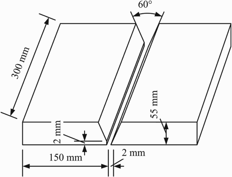
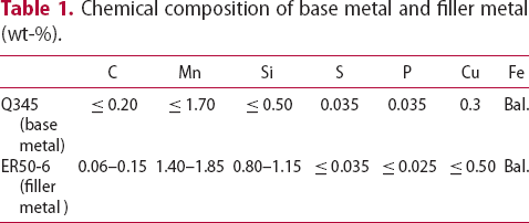
Chemical composition of base metal and filler metal (wt-%).
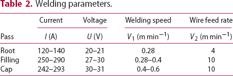
The two specimens were welded with nominally identical welding parameters, as given in Table 2. There were 27 welding passes to complete the first specimen and 28 passes for the second. The first specimen was joined with conventional GMAW, while LUIT was used during welding of the second specimen. Figure 2 illustrates the typical welding process with LUIT, in which several beads were deposited first, and then treated by UIT. Welding and UIT are then performed alternately until the groove is fully filled and finally the weld toe and the cap weld are treated by UIT.
Schematic of the GMAW with LUIT. (a) Filling the groove to a certain height; (b) UIT on the weld metal; (c) continuing bead deposition; (d) UIT on the newly deposited beads; (e) welding and UIT alternately until the groove is fully filled and final UIT on the weld toe and weld cap. Welding parameters.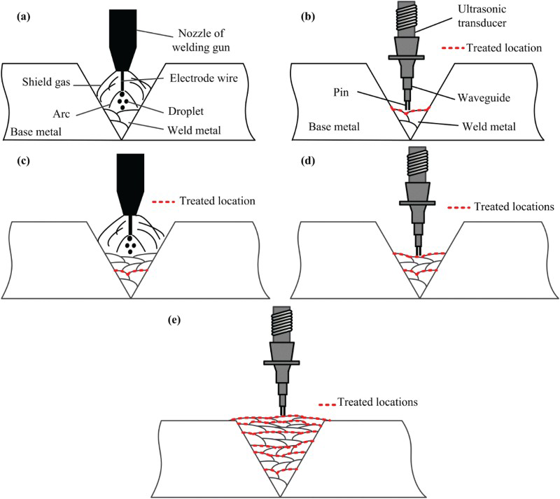
In order to clearly investigate grain growth on the UIT-processed surface, the UIT on the weld toe and cap (step e in Figure 2) was not performed in the present study. The weld profiles and the welding sequences of the two specimens are shown in Figure 3, where the UIT-processed beads are shown with red dashed lines. In the present study, UIT was first performed after the groove was filled to the height of 15 mm.
Weld profiles and welding sequences. (a) Weld profile of the conventional welding specimen; (b) weld profile of the LUIT-processed specimen; (c) welding sequence of the conventional welding specimen; (d) welding sequence of the LUIT-processed specimen (scales visible in (a) and (b) are in cm).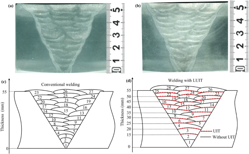
The UIT device used in the present study is model JSKD-D made by Jiangsu University of Science and Technology. There are four pins in the impact head and each pin has a diameter of 3 mm. The operational frequency of the ultrasonic driver is 20 kHz, but the pins impact the surface at lower frequency (about 100–200 Hz). The weight of the UIT tool (about 4 kg) reacts the pin contact forces. UIT was performed with care, so as to prevent unsteady tool movement and to ensure consistent treatment. UIT was stopped when the treated surface was bright in appearance and contained a uniform distribution of small indentations. The impact strength, defined as UIT process time divided by the treated area, was 10 s cm−2. The appearance of the weld metal after typical UIT is shown in Figure 4.
Appearance of a weld surface after UIT.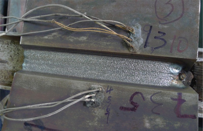
Residual stress measurement with contour method
To measure internal stresses of the specimens, the contour method (CM) [20] with two cuts was adopted in the current work. The first cut was performed along the middle cross-section and the second cut along the weld centreline. The schematic of the cut planes is shown in Figure 5.
Schematic of the cut planes.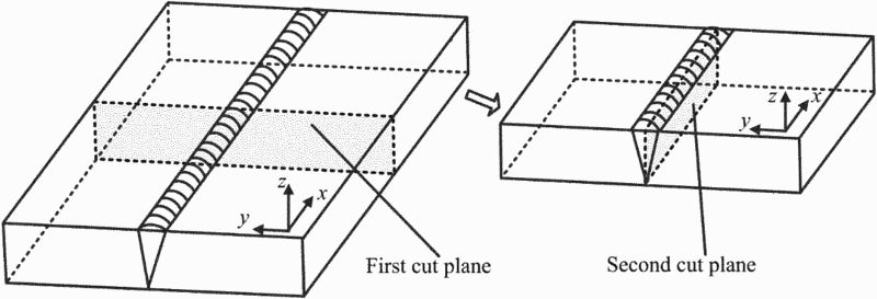
As a typical application of the CM [20], the first cut provides a two-dimensional (2D) map of the longitudinal stress as a function of position in the first cut plane, σxx(y, z) (coordinates are shown in Figure 5). The second cut provides a 2D map of the transverse stress in the second cut plane, σyy(x, z), which requires a modest extension of the typical CM [21,22] that relies on superposition of transverse stresses found in the first and second cuts.
While theoretical details for the CM can be found in the references [20–22], we provide a summary of implementation here for the three key stages of the contour measurements: (1) cutting of the part, (2) measuring and fitting of cut surface contours, and (3) computing residual stress. The cuts for CM were made using a wire electric discharge machine (EDM) (Sodick AQ400Ls) with a 250 μm diameter brass wire at a nominal cutting speed of 0.15 mm s−1. The weld was securely clamped during cutting with a custom fixture, as shown in Figure 6 (the diagram does not show the clamping screws, so that it clearly shows locations of the clamping plates).
Schematic of clamping arrangement for the EDM cut.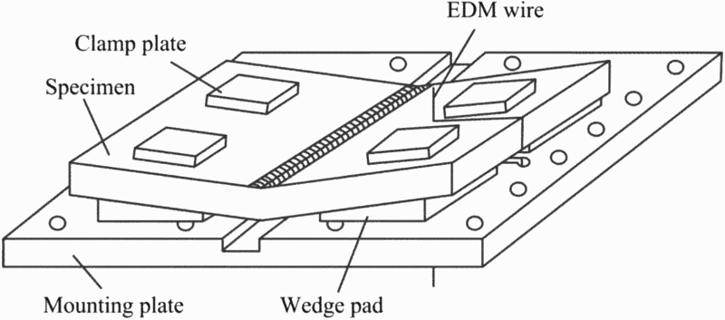
After cutting, the joint was removed from the fixture and the contours of the cutting surfaces were measured using a Hexagon Global Performance coordinate measuring machine. Cut surface shapes were measured by collecting surface height at a grid of in-plane locations. For the first cut, the grid spacing was 2 mm in the y- and z-directions, except close to the weld centre where the spacing was 1 mm. For the second cut, point spacing was 2 mm in the x- and z-directions. For each cut, the surface contour data from the two opposing surfaces were carefully aligned, interpolated onto a common grid and pointwise averaged. Then, the averaged contour was fit to a smooth surface using bivariate splines.
Fitted cut surface contour data provide a displacement input to a linear elastic finite element stress analysis that provides residual stress. The stress analysis used a finite element representation of the half specimen (after cutting) geometry and was developed using ANSYS software. The mesh was composed of 8-node structural solid elements (Solid185) with a nominal 1 mm mesh size. Linear elastic properties were Young's modulus of 200 GPa and Poisson's ratio of 0.33. The negative of the fitted cut surface contour was imposed as an out-of-plane displacement boundary condition at the surface of the mesh corresponding to the cut plane. Minimal constraints were applied to the FE model to prevent rigid body motion. The elastic analysis provided a 2D map of residual stress on the cut plane.
Hardness measurement and microstructure examination
After measurement of residual stresses with the CM, blocks with dimensions of 65 mm × 55 mm × 20 mm were cut from the joints and micro-hardness measurements were recorded to provide an understanding of the hardness distribution within the weld zones with and without LUIT. The measurements were automatically taken using a KBS30s Vickers hardness tester and by applying a load of 200 gf. The hardness measurement spacing along the transverse direction (y-direction in Figure 5) is 1 mm and that along the thickness is 2 mm.
The blocks were also used to investigate the microstructure in the weld zones. After being carefully polished, theses blocks were etched for 1–5 s using a solution of 3% nitric acid (HNO3) and 97% alcohol, and then the microstructures in the weld zones were examined using a ZEISS metallographic microscope.
Results and discussions
Microstructures
Figure 7 shows the microstructures in the welds of the two specimens. The columnar grain structure can be easily observed in the weld zone of the conventional welding specimen, as shown in Figure 7(a, c). The columnar grains grow from the fusion boundary following the heat flow of the welding process. Because of the thermal cycles from subsequent beads, heat affected zones are present between beads, with fine-grain microstructure as shown in Figure 7(b). But, the zones with fine-grain structure are very narrow, and the conventional GMAW weld is dominated by the coarse, columnar grains. Coarse columnar grains can exhibit reduced deformation capability and crack growth resistance and, further, are susceptible to impurity segregation that lowers cohesive strength and induces embrittlement [23]. Thus, conventional GMAW welds with large columnar grains can be a weak link in welded structures.
Comparison between the microstructures in the weld zones of the two specimens. (a) Pass 3 in the conventional welding specimen; (b) the intersection zone between pass 2 and pass 3 in the conventional welding specimen; (c) pass 2 in the conventional welding specimen; (d) pass 3 in the LUIT-processed specimen; (e) the beads intersection zone between pass 2 and pass 3 in the LUIT-processed specimen; (f) pass 3 in the LUIT-processed specimen.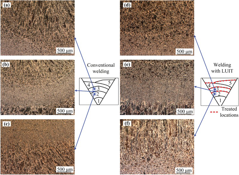
In the LUIT-processed specimen, pass 3, which was deposited on the UIT-processed surface, exhibits a fine equiaxed-grain microstructure (as shown in Figure 7(d)); however, pass 2, which was deposited on the un-treated surface of pass 1, has a coarse columnar grain microstructure (see Figure 7(f)). Therefore, the UIT-processed surface affects the grain growth behaviour of the subsequent bead, resulting in an equiaxed-grain structure. The fine equiaxed-grain microstructure also appears in the intersection region of the two beads (heat affected zone) as shown in Figure 7(e).
To further illustrate effect of the UIT-processed surface on grain growth in subsequent beads, we document microstructure in a region with several beads near the top of the LUIT specimen in Figure 8. Figure 8 shows that the microstructures in the weld zone of the LUIT specimen are complex. Equiaxed microstructure (as shown in Figure 8(a–e)) and columnar grain microstructure (Figure 8(b,f)) are found in the weld zone. The weld metal shown in Figure 8(b,d) belongs to the same pass (pass 20), but the microstructures at these locations are different. The metal at location b, which was deposited on the un-treated surface of pass 18, exhibits a columnar grain structure. However, the metal at location d, which was deposited on the UIT-processed surface of pass 17, is equiaxed. Therefore, welding on a UIT-processed weld surface causes the subsequent bead to be equiaxed. The equiaxed grains at locations a and c confirm the presence of fine, equiaxed grains in weld metal deposited on UIT-processed weld beads. The microstructures in Figure 8(e,f) further demonstrate that UIT affects subsequent beads. The bead at location e, deposited on UIT-processed pass 17 and UIT-processed base metal, shows equiaxed grains (Figure 8(e)). Conversely, the bead at location f, deposited on untreated pass 14 and adjacent untreated base metal, exhibits columnar grains (Figure 8(f)). Therefore, fine equiaxed grains can grow from the fusion zone boundary when beads are deposited on UIT-treated base metal.
Microstructures at different locations in the LUIT-processed weld. (a) Pass 23 deposited on UIT surface; (b) pass 20 deposited on un-treated surface; (c) pass 14 deposited on UIT surface; (d) pass 20 deposited on UIT surface; (e) pass 20 deposited on UIT surface and base metal; (f) pass 17 deposited on un-treated surface and base metal.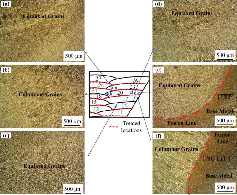
From the microstructures presented in Figures 7 and 8, it can be concluded that the UIT-processed layer changes the solidification and grain growth behaviour of beads laying on it, resulting in a fine equiaxed-grain structure. The factor that causes the beneficial effect of UIT-processed surface on the grain growth of subsequent beads should be the great extent of grain nucleation induced by the UIT-processed surface. Owing to the severe plastic deformation combined with rapid friction heating and cooling during UIT, grains at the UIT-processed surfaces are broken up and refined, and have nanocrystalline features, which in turn provide additional sites for grain nucleation when beads are deposited on it. Nucleation in the weld pool can block off columnar grains growing epitaxially from the fusion boundary, in addition, the greater the extent of nucleation, the more grain refinement in the weld metal [5]. Therefore, the UIT-treated surface contributes to a greater extent of nucleation, resulting in fine and equiaxed grain growth in subsequent beads.
Hardness distribution
The hardness measurement results are shown in Figure 9. The weld profile and the heat affect zone (HAZ) profile are also distinguished with lines in the figure (black dotted lines are the boundaries of the weld and the red dashed lines are the boundaries of the HAZ). From Figure 9, it can be seen that, for the conventional welding specimen, the hardness in the region from the top surface to a depth of about 25 mm ranges from 210 to 250 HV, while the hardness varies from 190 to 210 HV deeper within the weld. The lower hardness is consistent with the tempering caused by the thermal cycles of subsequent weld passes. A similar hardness distribution was found in a multi-pass P91 steel weld with a thickness of 25.4 mm [24]. For the LUIT specimen, the hardness within the entire weld varies from 210 to 250 HV, which is more uniform and overall higher than that for the conventional welding specimen. The higher hardness in the LUIT-processed specimen is consistent with a finer equiaxed-grain structure.
Hardness distributions on the cross-section (dimensions in mm).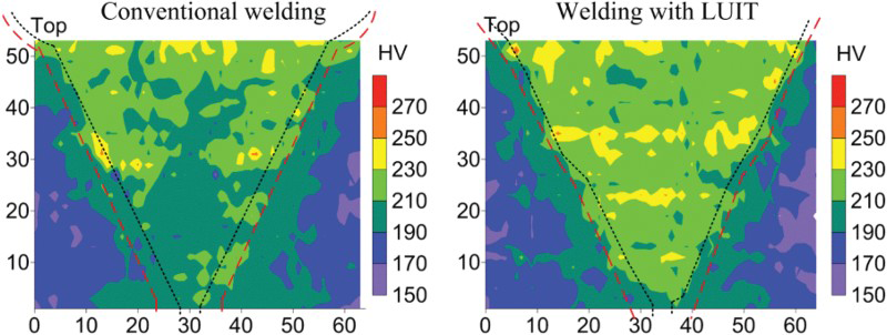
Residual stress distributions
Figure 10 shows the longitudinal and transverse residual stresses measured by the CM. As seen from Figure 10, the trends for the longitudinal and transverse stress distributions in the two specimens are very similar. The tensile longitudinal stress appears within the weld zones, being more tensile near the top and bottom surfaces than at the mid-thickness. The peak tensile longitudinal stress (about 430 MPa) appears about 10 mm below the top surface. At the weld centreline, tensile transverse stress is present near the top and bottom surfaces, and compressive stress appears in the interior. The transverse stress near the bottom surface is larger than that near the top surface, and the peak tensile transverse stress occurs near the bottom surface. Uncertainty of CM tends to be larger at the boundaries of the cut planes, due to limits on cutting and contour measurement [21,25,26], and therefore the isolated tensile regions appearing near the left and right edges in the longitudinal stress maps of Figure 10 may be uncertain.
Residual stress distributions measured with CM. (a) Conventional weld joint; (b) LUIT-processed joint.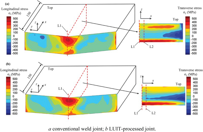
Line profiles of stress through the thickness at the weld centreline (line L1 and line L2 in Figure 10) are shown in Figure 11, with longitudinal stresses along line L1 and transverse stresses along L2. The line profile shapes suggest similar stress fields in the two specimens, with a trend for slightly lower stress in the LUIT specimen. Longitudinal stress is lower for the LIUT weld than for the conventional weld in the bottom half, from 2 to 32 mm on the vertical axis of Figure 11(a). Transverse stress is also lower for the LUIT specimen, but near the mid-thickness, from 15 to 48 mm on the vertical axis of Figure 11(b). The difference in stress could be due to small differences in heat input for the two specimens, to measurement uncertainties, or to an effect from LUIT. Despite the differences, Figures 10 and 11 convey a strong similarity in stress distribution between the LUIT-processed specimen (without UIT on the toe and the final weld surface) and the conventional welding specimen.
Through thickness stress distribution at the weld centreline. (a) Longitudinal stress; (b) transverse stress.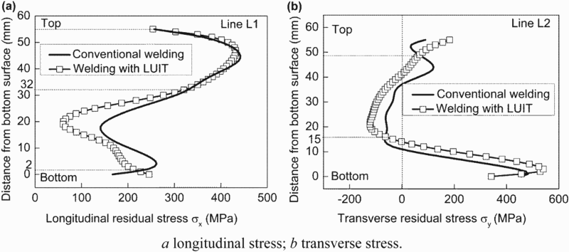
Previous research has shown that UIT can introduce a layer of compressive stress about 2 mm deep at the treated surface [17,27,28]. In the present study, UIT on the final weld surface was not applied, and the stress distributions in the LUIT-processed and conventional specimens were almost the same. This suggests that bead deposition on the UIT surface eliminated the stress fields induced by UIT. However, considering the beneficial effect of UIT (after the final passes) on the fatigue strength of welded structures [12,28] and the beneficial effect of fine, equiaxed microstructure on mechanical properties [5], results of the present study suggest that combining UIT of the final weld surface with LUIT would provide a weld with a compressive stress layer at the weld surface, and refined grains and uniform hardness through the thickness. These improvements could provide welds with reduced propensity for solidification cracking, and improved strength, ductility, and fatigue performance.
Conclusions
The microstructure, hardness distribution, and residual stress distribution in a thick joint processed by LUIT were investigated and compared with those in a conventional weld joint. The following observations were made:
A surface processed by UIT can provide additional sites for grain nucleation when weld beads are deposited on it, changing grain growth behaviour and promoting the growth of equiaxed grains from the fusion boundary and in the bulk of the weld bead. Because of a refined, equiaxed-grain microstructure, micro-hardness across the thickness of a 55 mm thick steel weld processed by LUIT is higher and more uniform than that in a conventional weld. The subsequent weld beads can eliminate the stress fields induced by UIT during multi-pass welding. Without considering UIT on the final cap weld and toe, the internal residual stress distribution in a 55 mm thick steel weld processed by LUIT was almost the same as that in a conventional weld.