
Abstract
Machining-induced residual stress plays significant role in the corrosion resistance and fatigue life of the manufacturing end-product. The high temperature condition in the turning process could induce microstructure changes of titanium alloys, which would directly influence the residual stress generation in the machining process. A prediction model is proposed to calculate the microstructure evolution in orthogonal turning process. Based on the explicit calculation of grain size growth and phase transformation, a microstructure-sensitive Johnson–Cook model considering the material microstructural attributes is developed for the machining-induced residual stress prediction of Ti-6Al-4V. Grain size characterization with electron backscatter diffraction test is conducted on the machined workpiece surface. Experimental measurement on force and residual stresses are conducted for model validations. The predicted force value agrees well with the measurement data. The general trend of residual stress profile is captured by the prediction model. The mechanisms of how the residual stress would be influenced by the different machining conditions, such as surface cutting speed, and feed rate, are also studied. The proposed method provides an in-depth understanding on the machined workpiece residual stress distribution as influenced by material microstructural attributes evolution in the machining process.
Introduction
Titanium alloys, especially Ti-6Al-4V alloy, serve as important material for components or structures in the medical and aerospace industry because of the superior physical and mechanical properties, such as biocompatibility and large strength to weight ratio.1–3 Severe mechanical loading and high temperature concentration in the machining process would change the surface integrities of the machined workpiece, especially in the aggressive machining process with high speed and large feed rate.4,5 The surface integrity, such as microhardness and surface roughness, is crucial for the machined part service functionality. Among all the workpiece surface integrity properties, the residual stress profile plays the dominating factor on the corrosion resistance and fatigue life.6,7 Large magnitude of residual stress could be generated from the severe plastic deformation and thermal-related expansion after machining. In case of surface tensile residual stresses occurs, it will significantly reduce the workpiece fatigue resistance. An afterward heat treatment or laser peening process would be required to release the stress.8,9
The machined workpiece tends to have tensile residual stress profile near the surface area. With the increasing depth into the workpiece, the tensile residual stress would change to be compressive. Extensive research has been conducted to measure or predict the machining-induced residual stress. As a pioneer work, Tsuchida et al. 10 experimentally studied how different machining process conditions could affect the residual stress profiles on carbon steel workpiece surface. They found out that, with the increasing machining speed, the magnitude surface of tensile stress would decrease. In addition, the increase in the feed rate tended to shift the surface stress from compressive to tensile. Liang and colleagues11,12 proposed an analytic method to predict the residual stress for two-dimensional (2D) orthogonal metal cutting. A hybrid contact mechanics model combined with kinematic hardening approach was employed for the stress and heat generation calculation. Özel and Ulutan 13 experimentally investigated the residual stresses on the workpiece surface in 2D orthogonal turning of titanium alloy. The chip formation and tool flank wear effects on residual stress profile were experimentally studies by Chen et al. 14 for Ti-6Al-4V material.
Although extensive research has been conducted for the residual stress prediction and measurement of the steel alloy, little work has shown in the application for turning of Ti-6Al-4V material. Another important aspect in machining titanium alloys is the microstructural evolution. Observation on the phase transformation and dynamical recrystallization are reported.15,16 The underlying mechanisms that dominate the considerable microstructure changes stay largely unknown. The understanding of the microstructural evolution process is important in the aspect of how it would influence the machined workpiece surface functionality. The crystal rearrangement and grain refinement would also possibly affect the material flow stress during the plastic deformation. The current research work aims to fill the void by providing a finite element model for 2D residual stress prediction with a comparison against experimental data. The finite element model incorporates a microstructural sensitive flow stress model which accounts for the dynamic grain size evolution and the phase transformation effects on the flow stress. Validation tests are conducted by comparing the predicted turning forces with experimental measurements. The predicted trends of the residual stress distribution are validated against experimental data.
Materials and methods
Machining experiment
The annealed cylindrical Ti-6Al-4V bar with a radius around 12 mm was used for turning experiment in this study. The uncoated polycrystalline cubic boron nitride (PCBN) cutting insert was selected as the cutting tool. The cutting tool edge radius was characterized to be 10 µm for the insert. The corner radius of the PCBN insert was 0.4 mm. The PCBN insert was mounted with a cycle select drive package (CSDP) tool holder to obtain a 5° rake angle and 11° relief angle.
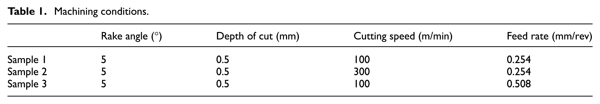
The experiments were performed on the Okuma Millac CNC lathe center, as shown in Figure 1. The cutting forces were recorded by a LabVIEW script with a dynamometer (Kistler 9257B) connected. The dynamometer transformed the force in x/y/z-direction into the corresponding voltage data, which was processed by a voltage amplifier. The tool holder was mounted onto the dynamometer to measure the machining forces. The depth of cut for orthogonal turning was fixed at 0.5 mm in the entire process. Two different surface cutting speeds 100 and 300 m/min were used to investigate the cutting speed effects on residual stresses. The tool feed rate varied from 0.254 to 0.508 mm/rev. The three sets of different machining configurations are listed in Table 1.
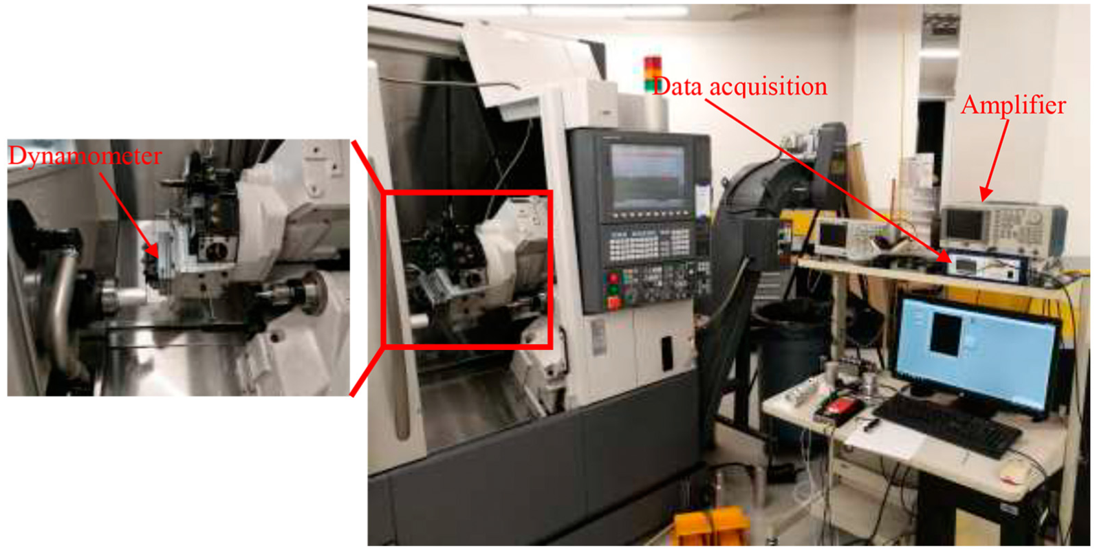
The machining experimental setup for the force measurement.
Machining conditions.
Grain size characterization
Electron backscatter diffraction (EBSD) tests were employed to characterize the grain distribution on the machined workpiece surface. The characterizations were conducted using a TESCAN MIRA X3 FE-SEM. The scanned region covers the machined surface and 200 µm below. The step size of the scan was 0.3 µm in both x- and y-directions. Experimental scan points below 0.1 of confidence index were filtered out (and colored in black in the images) to maximize the reliability of the results. The α phase volume fraction was determined to be 95% at the room temperature. The EBSD image of raw material is shown in Figure 2(a). The grain size ranges from 0.39 to 5.3 µm, as shown in the histogram in Figure 2(b). The initial average grain size on the workpiece surface is determined to be 2.28 µm.
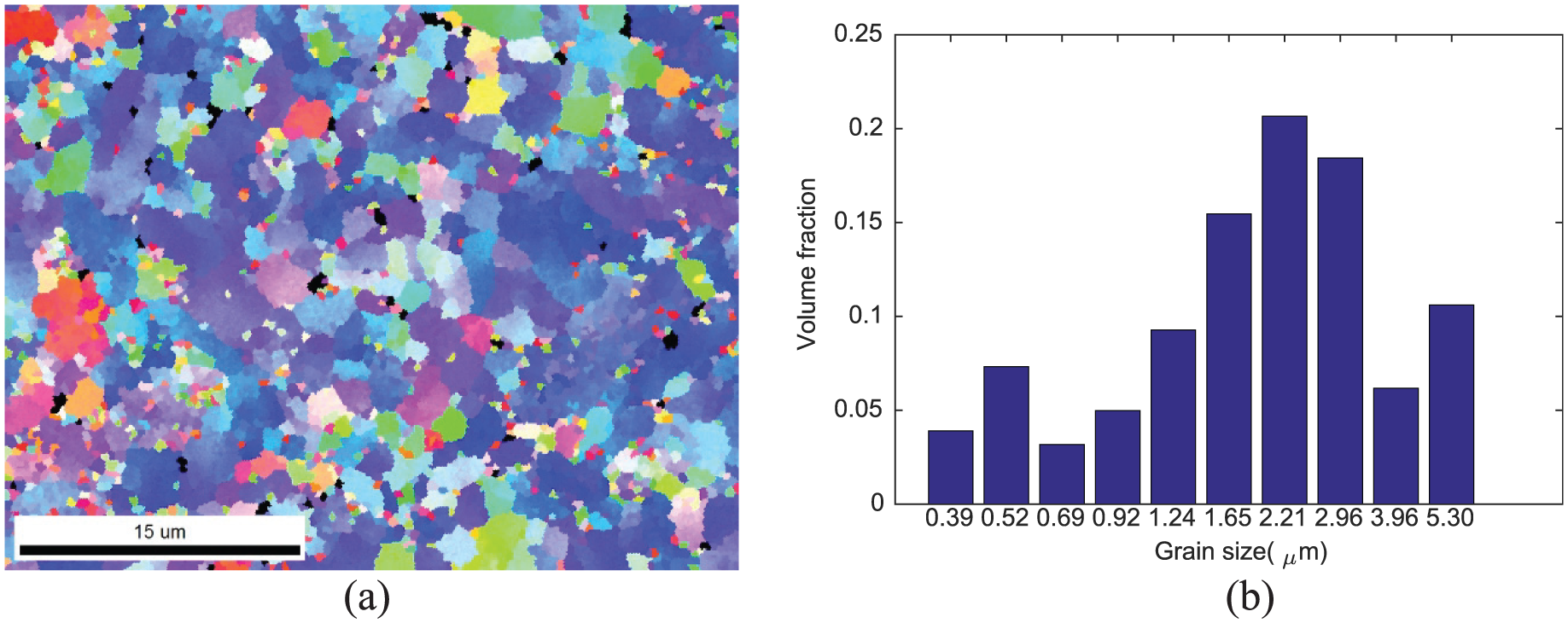
The EBSD images of the raw material microstructure states: (a) the grain size distribution of the α phase and (b) the histogram of the α-phase grain size.
Residual stress measurement
After all the machining experiments were completed, the stresses in the tangential direction (hoop stress) and radial direction (radial stress) were determined with X-ray diffraction machine. The Cr anode source with a 3-kW power input ceramic/metal X-ray tube is selected for X-ray generation. The measurements were conducted at seven tilting angles ranging from −20° to 20°. To get the residual stress as a function of depth into the workpiece, the layers on the workpiece were removed by electro-chemical polisher to expose the subsurface ready for the residual stress measurement. The proposed polishing method would not incur any additional stresses. The etchant agent was a 6 volume percent nitric acid (HNO3) with 3 volume percent hydrofluoric acid (HF) solution. The polishing process parameters, such as the polishing time, applied voltage, current, and amount of electrolyte, were properly adjusted to ensure a constant depth of layer removal of about 20 µm. The residual stress versus depth profile was obtained by removing successive layer of materials by the electronic polishing.
Finite element simulation
For the residual stress prediction with a finite element analysis (FEA) model, a constitutive relation is required to characterize the material flow stress response in terms of strain rate, strain, or temperature. In a general case, flow behavior of a certain material in the machining process is summarized as the Johnson–Cook (JC) model 17
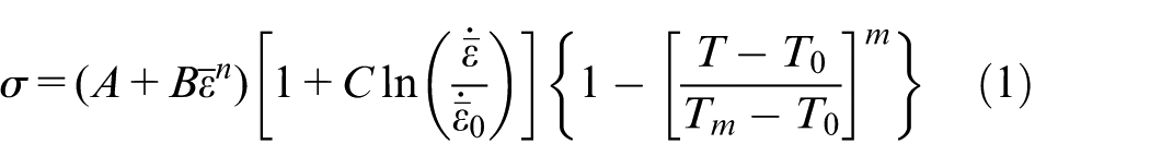
where A is the initial yield stress; B is the strain hardening coefficient; ε is the nominal plastic strain; n is the strain hardening index; C is the strain rate hardening coefficient;
The JC model is a mathematical interpolation model that fits yield stress in terms of strain rate, temperature, and strain. From the material aspect of view, the flow stress is strongly dependent on the microstructural properties of Ti-6Al-4V. However, there is no microstructural attributes term indicated in the traditional JC model. Because of the severe thermo-mechanical loadings in machining, the microstructural attributes could have significant changes. The texture, grain size, and phase composition can have significant variation on the machined workpiece material and chip determined by the machining conditions.
For Ti-6Al-4V material with a α + β phase composition, typically the strength and yield stress of the α phase is much larger than that of the β phase. Based on the different compositions of the material, the flow stress of Ti-6Al-4V at the room temperature can range from 850 to 1100 MPa as an effect of the microstructure properties variation. Another dominating factor for the Ti-6Al-4V yield strength is the α phase colony size. The finer grain structure would result in a much larger flow stress. At a continuum level, a simplified flow stress model could be proposed to include the microstructural properties, such as the average grain size and phase composition.
The phase transformation kinematics of Ti-6Al-4V involves complicated new colonies generation and precipitates diffusion. The final phase composition mainly depends on the heating or cooling rates and the material initial microstructural states. To simplify the model, two different phase transformation are assumed here, α → β, β → α+β. The α → β phase transformation in the heating or cooling down process is explicitly calculated based on Avrami equation, which is reported in a previous study. 18 The β → α+β is obtained from the time temperature transformation curve. The instantaneous volume fraction of the α and β phases could be explicitly calculated in the dynamic machining process. By calculating the flow stress of σα and σβ from equation (1), respectively, the material nominal flow stress could simply be calculated by a mixture rule as

where η is the volume fraction of α phase. For simplification, one assumption is made here that only A value, the initial yield strength, is phase dependent. So, A has different values for α and β phase. The assumption is valid because of that the initial yield stress contributes to the biggest difference to the flow stress between α and β phases, which is the A value. The flow stress at different phase compositions was summarized by Zhang et al., 19 a linear regression analysis here is used to obtain the A values.
The material dynamic recrystallization process for grain size growth is dependent on the thermo-mechanical loading in machining. A widely used method for calculation of metal dynamic recrystallization is based on the Johnson–Mehl–Avrami–Kolmogorov (JMAK) equations. 20 The grain size growth of the recrystallized material is obtained from the calculation of nucleation and grain growth rate in thermo-mechanical coupled deformation process. The detailed model description was proposed in a previous study for the calculation of the dynamical recrystallized grain size d. 21 As has been stated by Pederson, 22 the texture colony size is another dominating factor for the material strength in α+β titanium. In this study, an average grain size is proposed to represent the colony size for both α and β phases. The average grain size effect on the material strength is characterized by the Hall–Petch equation 23

where the Hall–Petch parameters Ahp and Khp are material dependent properties. From the previous assumption, only the Hall–Petch parameters are phase dependent. By linearly fitting the experimental flow stress data for Ti-6Al-4V, the Hall–Petch parameters could be obtained. For the α phase, the Ahp,α and Khp,α are determined to be 517.31 and 201.68 MPa µm0.5. The β phase constants Ahp,β and Khp,β are selected as 237.86 and 100.84 MPa µm0.5, respectively.
The complete set of JC parameters are listed in Table 2. A reference strain rate
JC model parameters for
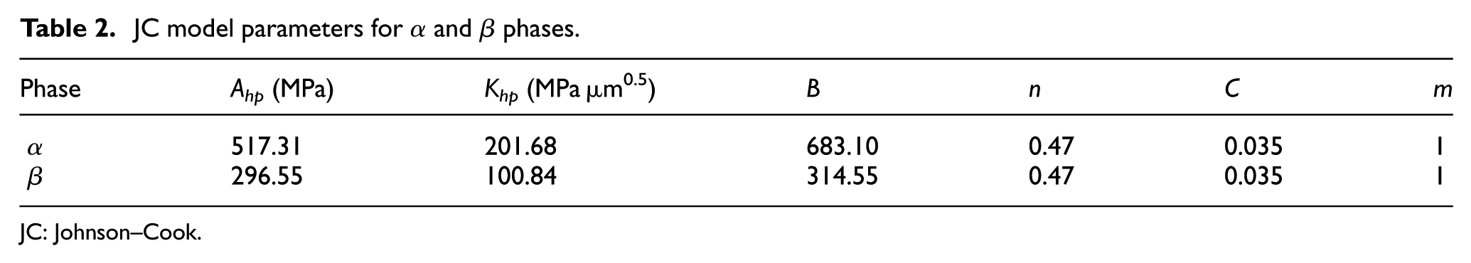
JC: Johnson–Cook.
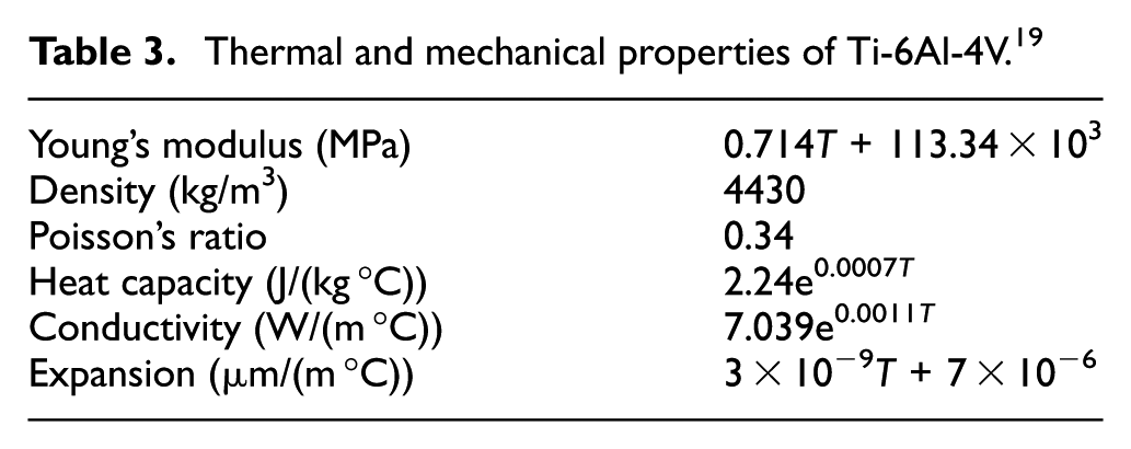
Thermal and mechanical properties of Ti-6Al-4V. 19
The classic Coulomb’s model is employed to characterize friction between the cutting insert and workpiece/chip contact interface. 24 A constant Coulomb shear coefficient µ = 0.7 is used. The determination of the friction coefficient between the tool and workpiece could be a trial and error process. In our previous research work, 21 the friction coefficient was determined by matching the segmented chip morphology with the experimental data in an orthogonal turning experiment. The 2D turning of Ti-6Al-4V is conducted in a commercial finite element code DEFORM for the comparison with the experimental results. The FEA model for the machining configuration is shown in Figure 3, with a total number of 9000 elements for the workpiece.
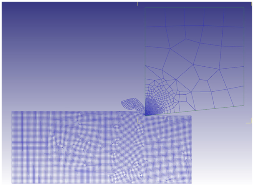
The FEA model for the machining force and residual stress prediction.
For the residual stress calculation on the machined surface, the elastic plastic constitutive material model is used. In the machining, the residual stress is mainly from the uniform material plastic deformation, thermal expansion, and phase transformation–induced volume change. In this study, since we are assuming the α phase and β phase have the same density, the phase transformation–induced volume change is not considered. After uniform thermal and mechanical loading, the final stress states on the machined workpiece are the residual stress induced from machining. From the FEA simulation, the residual stress is obtained from the machined surface where the machining process comes to the steady state.
Results and discussion
The measured forces at varying surface cutting speeds and tool feeding rates in the machining experiments are plotted in Figure 4. Also, the corresponding force predictions are plotted against the measurement data. The predicted machining forces show close approximation to the experimental measurement. At a constant tool feed rate, as the surface cutting speed increases, the forces in both cutting and feed directions FC, Ff do not have obvious change. The shear stress in the shear plane is a function of strain, strain rate, and temperature. By ignoring the cutting speed effect on the chip morphology, the strain could be assumed to be the same at different cutting speeds. The increasing cutting speed would result in a linear increase in the strain rate. However, the significant temperature increase in the shear plane reduces the material flow stress. So, the forces in the cutting direction and feed direction do not show obvious change. However, plowing force FP has obvious decrease. By varying the feed rate, both the cutting force and feeding force increase with the increasing feed rate, as shown in Figure 4(a) and (c). However, the plowing force only has slight increase with the increased feed rate.
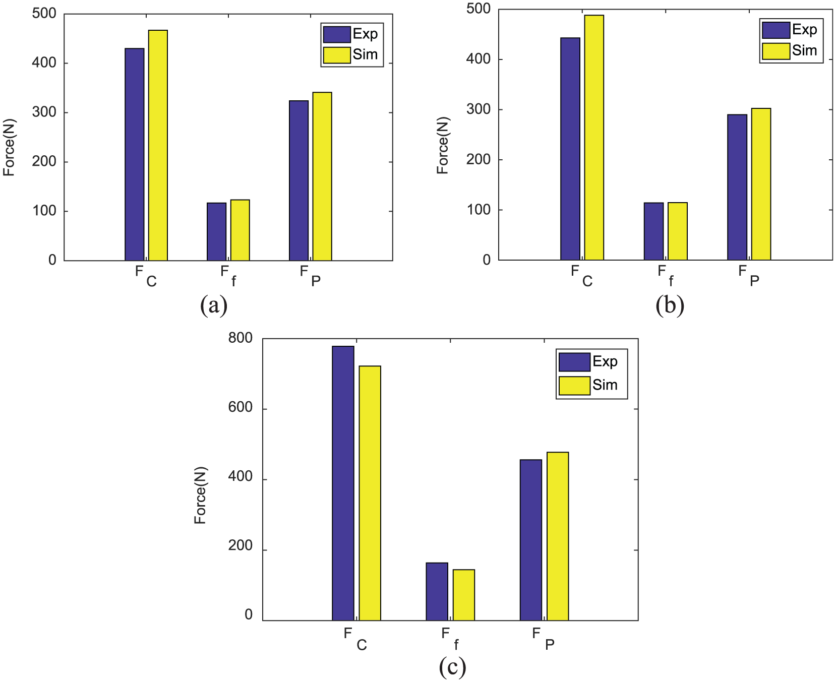
The machining forces measured in the different cutting conditions: (a) cutting speed of 100 m/min, feed rate of 0.254 mm/rev; (b) cutting speed of 300 m/min, feed rate of 0.254 mm/rev; and (c) cutting speed of 100 m/min, feed rate of 0.508 mm/rev.
At the room temperature, machined surface microstructure states are characterized by EBSD, as shown in Figure 5. Since the Ti-6Al-4V material is α-phase dominant with a 95% volume fraction at room temperature. The EBSD images only show the α-phase grain distribution. The average grain size with a machining speed of 100 m/min is 3.02 and 3.29 µm for 300 m/min as shown in Figure 5(a) and (c). Compared with the initial average grain size of 2.28 µm, the machined surface grain size has obvious increase due to the dynamic recrystallization under the thermal-mechanical loading.
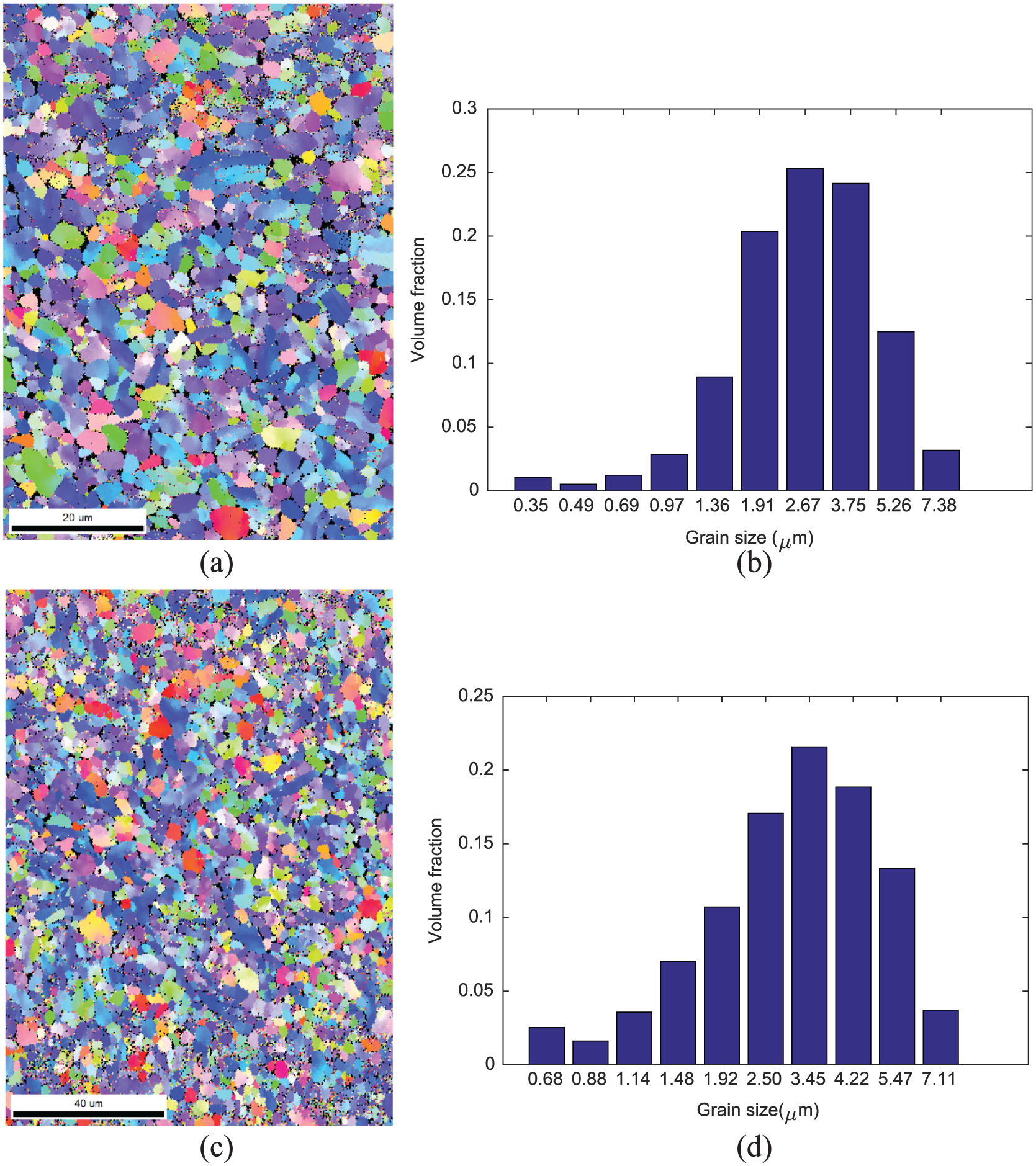
At the feed rate of 0.254 mm/rev, cutting speed of 100 m/min, the EBSD image of the α phase on the machined workpiece surface (a), histogram of α-phase grain size (b); at the feed rate of 0.254 mm/rev, cutting speed of 300 m/min, the EBSD image of α phase (c), histogram of α-phase grain size (d).
With the validated model by machining forces, three more turning cases are simulated in 2D orthogonal turning configuration for residual stress prediction. The residual stresses are determined when the workpiece temperature returns back to the room temperature to allow for the possible spring back. The measured residual stresses are summarized in Figure 6. The hoop stress is measured to be tensile and reduces to zero as the depth increases. The radial residual stress after machining on the workpiece surface is compressive, as shown in Figure 6(a) and (b). It decreases to zero with the increasing distance from the surface. At a constant tool feed rate, when the surface cutting speed increases, both magnitude of radial residual stress and hoop stress on the workpiece surface increase. A similar trend is found between the model prediction and experimental measurement on how the cutting speed affects the hoop residual stress, as indicated in Figures 6 and 7. As for how the feed rate influence the residual stress distribution, both the workpiece machined surface hoop stress magnitude and radial stress magnitude have increased when the tool feed rate increases from 0.254 to 0.508 mm/rev, as shown in Figure 7(a) and (c). The increasing feed rate would result in the increased magnitude of both the compressive residual stress and tensile residual stress on the machined surface. This is because larger feed rate would require large cutting forces. This increased cutting force would induce more material plastic deformation on the machined surface. So, the magnitude of machining-induced residual stress becomes larger. In the cutting speed case, the magnitude of the cutting force would decrease when the cutting speed increases. So, the magnitude of the residual stress would decrease, as compared in Figure 7(a) and (b).
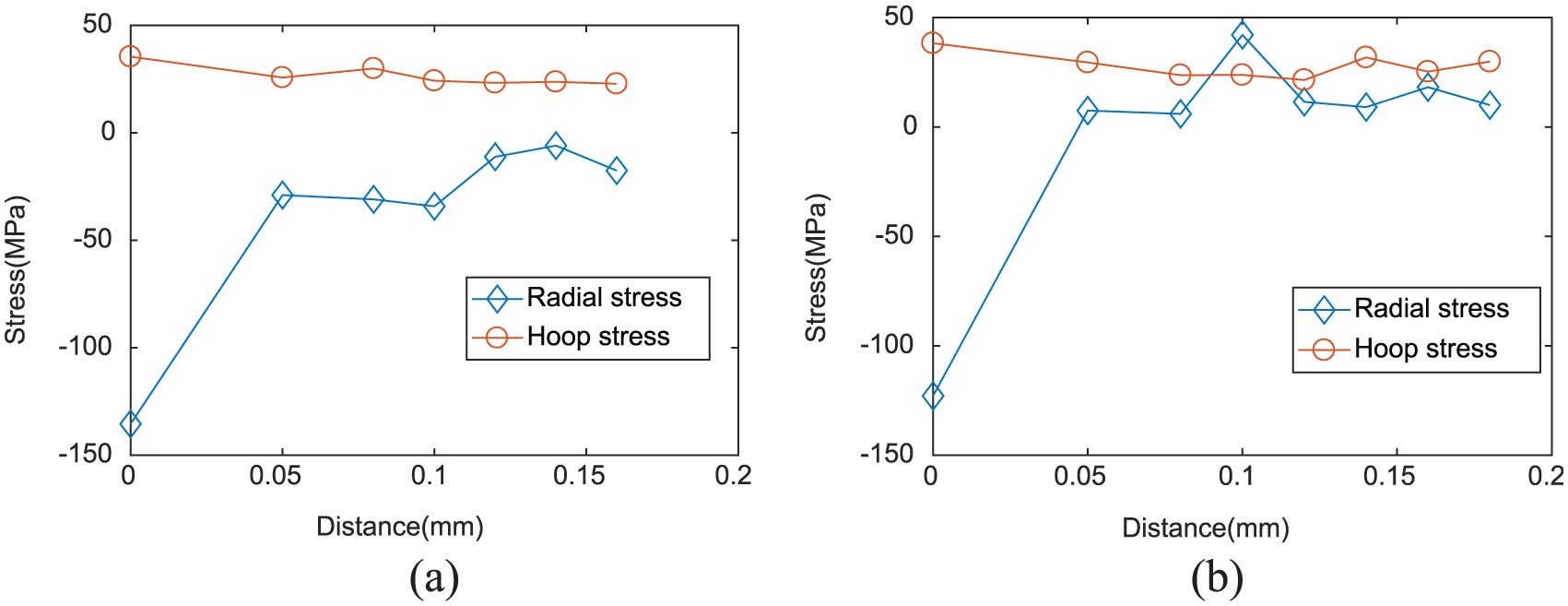
The measured residual stress as a function of distance to the workpiece surface different cutting speeds at (a) 100 m/min and (b) 300 m/min.
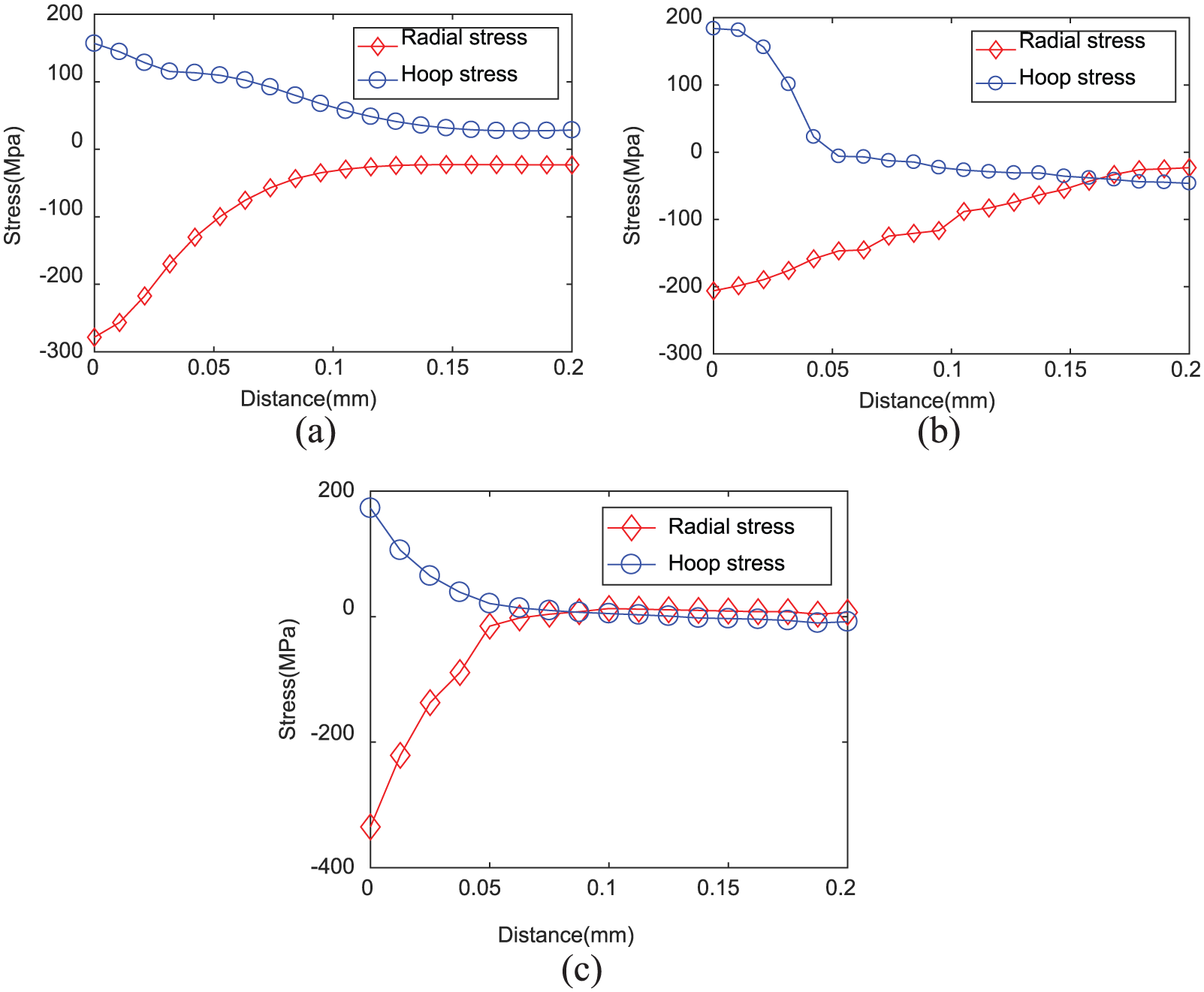
The predicted residual stress as a function of distance to the workpiece surface with varying cutting speed and feed rate: (a) cutting speed = 100 m/min, feed rate = 0.254 mm/rev; (b) cutting speed = 300 m/min, feed rate = 0.254 mm/rev; and (c) cutting speed = 100 m/min, feed rate = 0.508 mm/rev.
Conclusion
In this study, a finite element based microstructural sensitive flow stress model is proposed for the determination of machined workpiece surface residual stress in the 2D orthogonal turning process. Based on the explicit average grain size and phase transformation calculation, a microstructure-sensitive flow stress model is proposed to include material microstructural attributes change into a modified JC model. The proposed model is implemented into finite element model for machining forces and residual stress profile prediction of Ti-6Al-4V workpiece material in the 2D orthogonal turning. The model is validated by the machining forces in varying feed rates and cutting speeds. EBSD characterization shows the obvious grain growth on machined workpiece surface. The proposed method could be easily applied for residual stress and machining force prediction of multiphase material in the field of milling, drilling, or grinding.
Footnotes
Declaration of conflicting interests
The author(s) declared no potential conflicts of interest with respect to the research, authorship, and/or publication of this article.
Funding
The author(s) disclosed receipt of the following financial support for the research, authorship, and/or publication of this article: This work was supported by the Georgia Institute of Technology Manufacturing Research Institute.