
Abstract
The numerous unique advantages afforded by rotary ultrasonic machining have led to its extensive utilization in machining hard–brittle materials. However, the material removal mechanisms are still not very clear, leaving many uncertainties of the machined components in practical application. In this research, machining/scratching tests had been undertaken on optical glass K9 with diamond tools under various process parameters. Surface morphologies were characterized using a measuring microscope, white-light interferometer and scanning electron microscope. On the basis of these examinations, the effects of ultrasonic vibration on the material removal mechanisms were investigated. As a result, another material removal mechanism, pulverization, was identified besides brittle fracture and plastic deformation. The pulverizable areas, which resulted from the force of the tortuous cracks propagation, were found to be prominent in the surrounding fracture areas. In addition, the influence of the pulverizable areas on the surface roughness was also investigated. The scratching results presented that the pulverization was induced by the impact effects of the abrasive at the vertex of its sinusoidal trajectory. The vertical inertia force of the abrasive and the inertial effects of the material, which were induced by the immense acceleration of single abrasive at the vertex of its sinusoidal trajectory, should be conducive to the nucleation of the first cracks.
Keywords
Introduction
Optical glass K9 has been extensively applied in high quality optical components owing to its low level inclusion and stable optical qualities. Although K9 glass has several positive properties, owing to its high brittleness and hardness natures, it is generally considered to be difficult to machine, which restricts its extensive applications. Rotary ultrasonic machining (RUM), characterized by small cutting force, high material removal rate (MRR) and good surface quality, is a cost-effective machining process available for hard–brittle materials. 1 Though RUM has been wildly adopted to fabricate brittle material components, the material removal mechanisms are not fully recognized.
To obtain fundamental information on RUM of the brittle material process, experimental investigations have been conducted by worldwide scholars.2–5 Based on the direct observations of the RUM surfaces, two material removal mechanisms, namely brittle fracture and ductile deformation, are identified. 5 In earlier literature, it was thought that an intensive brittle fracture process of the material, induced by ultrasonic vibrations, was the only material removal mechanism. With successive ultrasonic impacts of the abrasives, micro and macro-cracking occur and spread to some depth, which cause a weak layer on the workpiece surface. 6 These cracks greatly hasten the fragmentation of the brittle material. Under repeated impacts of the abrasives, the material breaks down from the brittle body with conchoidal fractures.7–9 Under enlightenment from the ductile regime machining of brittle materials in diamond turning 10 and conventional grinding (CG), 11 plastic flow is also observed on the RUM surface, which is considered as another material removal mechanism. 4 In the sequel, an approach to modeling the ductile material removal mode is also developed. 12 However, in the investigations mentioned previously, no systematical investigations of the vibration effects of abrasives on the material removal mechanisms have been reported.
Furthermore, in the dynamic RUM process, the diamond tool vibrates in its axial direction with high frequency and low amplitude, which results in immense acceleration of a single abrasive. After the abrasive penetrates into the material, the immense acceleration results in a large strain rate of the material. Phenomena, for which the strain rate dependent material properties and the inertial force of the abrasives that have a significant effect on the material removal mechanisms, are typically included. However, the phenomena have been ignored by former researches.
In the present research, the direct observations of RUM surfaces were conducted, as it could provide key information on the surface characteristics. On the basis of these observations, the material removal mechanisms correlation with the surface characteristics were discussed. Surface roughness, which was also an indicator to characterize the material removal mechanisms associated with the RUM process, was also studied. Moreover, the present research had, for the first time, successfully adopted the kinematics characteristics of the abrasives and the dynamic fracture mechanics properties of the material to investigate the material removal mechanisms in the brittle material removal regime.
Kinematic principles of diamond abrasive
Figure 1 shows the schematic diagram of the RUM process. A high-speed rotating hollow tool with metal-bonded diamond abrasives was ultrasonically vibrated in its axial direction and fed along the workpiece surface with a constant feed rate. A coolant system (internal and external coolant) applied water with a special high-pressure pump and jetted through the center hole of the diamond tool to wash away the debris and cool the tool simultaneously.
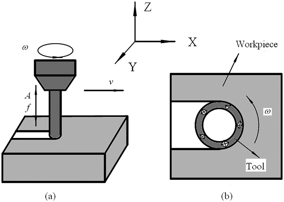
Illustration of the RUM process with a diamond tool.
In RUM, an additional axial vibrating active motion of the diamond tool was superimposed on the kinematics of the CG process. So the motions of the abrasive, located on the tool end face, included feed motion, rotation and ultrasonic vibration in the tool axis direction. If the feed speed was ignored, the trajectory of one diamond abrasive could be described as

where
As the trajectory of the abrasive, located on the tool end face, periodically changed, its instantaneous velocity cyclically changed. In each ultrasonic vibration cycle, the velocity value of the abrasive could be described as

In addition, the diamond tool vibrated in its axial direction with a high frequency and low amplitude, which led to the large acceleration of a single abrasive. The vibration acceleration equation of one abrasive in the tool axial direction could be deduced as

According to equations (1)–(3), Figure 2 presents the trajectory, instantaneous velocity and vertical acceleration of one abrasive versus its tangential displacement, in the case of
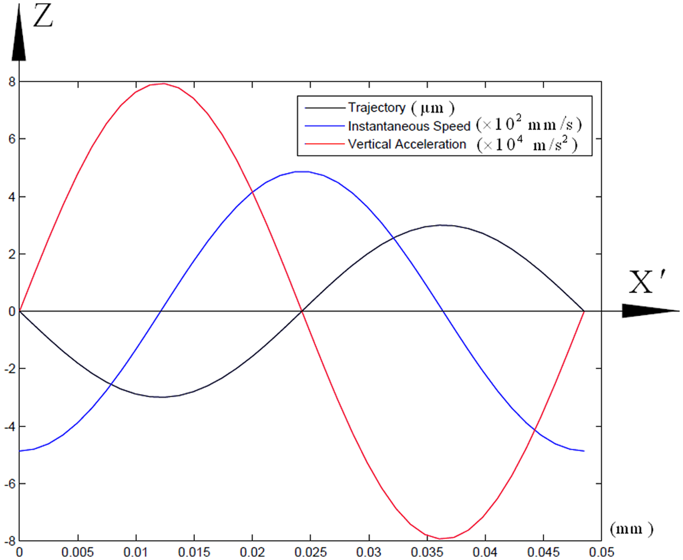
Trajectory, instantaneous velocity and vertical acceleration of one abrasive versus its tangential displacement.
The ultrasonic vibration fundamentally altered the relative motion relationship between the diamond abrasive and the workpiece, and changed the RUM process and material removal mechanisms as a consequence.
Experimental procedures
Specimen
The workpiece material selected for this investigation was optical glass of K9. The specimens had dimensions of
Machining/scratching tests
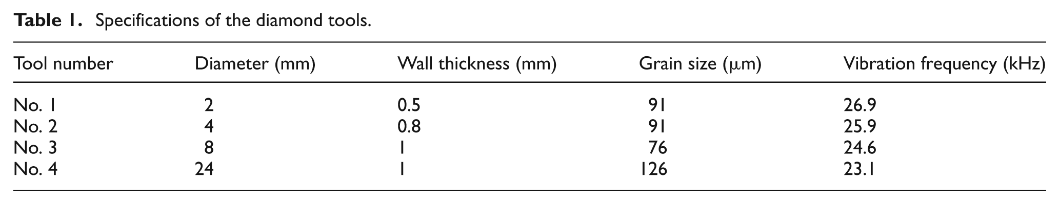
Machining/scratching tests were performed on a Sauer Ultrasonic 20 (DMG, Germany), which enabled classical three-axis CG as well as RUM. The machine was equipped with a high-speed ultrasonic spindle having a speeding range of 0–20,000 r/min and a slideway with a speed range of 0–4000 mm/min. The spindle had an axial positioning resolution of 0.1 µm, which allowed the machining to control the cutting depth. The mechanical ultrasonic vibration was generated by a piezo-actuator integrated within the actor system of the HSK32 tool holder. It should be noted that, for a specific diamond tool, the ultrasonic vibration frequency was a constant value. Four nickel-body diamond coating tools, with different grain sizes and diameters, were selected for this research (with a diamond concentration of 100%). The specifications of the diamond tools are listed in Table 1, and the optical micrographs of tool 2 are plotted in Figure 3. To compare the surface characteristics produced in RUM and CG processes, a set of cavities were machined with a zigzag path in the direction of cutting depth using different tools and process parameters, as detailed in machining test 1. The CG test was conducted with tool 4 by disabling the ultrasonic vibration system. Scratching test 2 was conducted to investigate the influence of the ultrasonic vibration on the material removal process. For eliminating the influences of interruption among scratches generated by different abrasives on analyzing the damage characteristics, the specimens were tilted with regard to the feed motion by a few micrometers in order to realize various depths of scratch induced by the abrasive with highest penetration. In order to investigate the effects of the process parameters on the surface roughness, feed speeds of the diamond tool 2 were set to 200, 400 and 600 mm/min and spindle speeds were at 3000, 6000 and 9000 r/min for machining test 3. In all the tests, the specimens were attached on a platform that was firmly fixed on the machine table. A water-based synthetic solution (8% soluble type dilution) was used as the machining coolant. After machining, the specimens were subsequently separated by heating the platform to soften the adhesive. The machining/scratching process conditions can be seen in Table 2.
Specifications of the diamond tools.
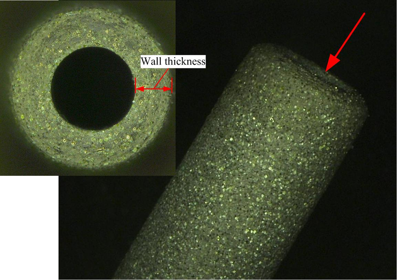
Optical micrographs of the diamond tool 2.
Machining/scratching process conditions.
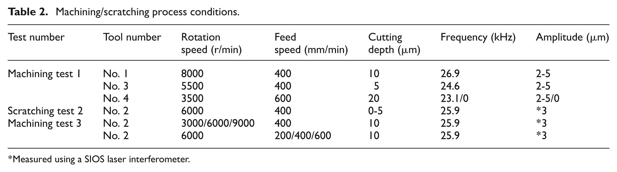
Measured using a SIOS laser interferometer.
Post-tests evaluation
After each machining/scratching test, the machined specimens were cleaned with acetone in an ultrasonic bath for at least 20 min. Then, the machined surfaces generated in test 1 were coated with gold and inspected using a scanning electron microscope (SEM) Inspect F (FEI, USA) to identify the surface morphology in detail. The observations of the surface characteristics produced in the scratching test 2 were conducted with a measuring microscope STM6 (OLYMPUS, Japan) and white-light interferometer NT1100 (WYKO, USA), which was also used to identify the relative height of different locations of the specimen surfaces. On the basis of the surface observations, the material removal mechanisms were investigated. The surface roughness Ra of the workpieces generated in test 3 was measured with a surface profilometer Alpha-Step xp-200 (KLA Tencor, USA) perpendicular to and parallel to the feed direction. The roughness was the average value (average of seven measurements) obtained by scanning the center of the cavities at different locations.
Experimental results
Surface characteristics and material removal mechanisms
Typical SEM micrographs of the CG and RUM surfaces generated in test 1 are depicted in Figure 4. The CG surfaces consisted of a complex network of overlapping grinding marks, which were impossible to characterize individually, as shown in Figure 4(a). Micro-chippings, resulting from crack system formation and spreading, were identified on the flanks of the grinding marks. These marks were overwhelmed by the micro-chippings, which implied the main material removal mechanism, including brittle fracture. 13
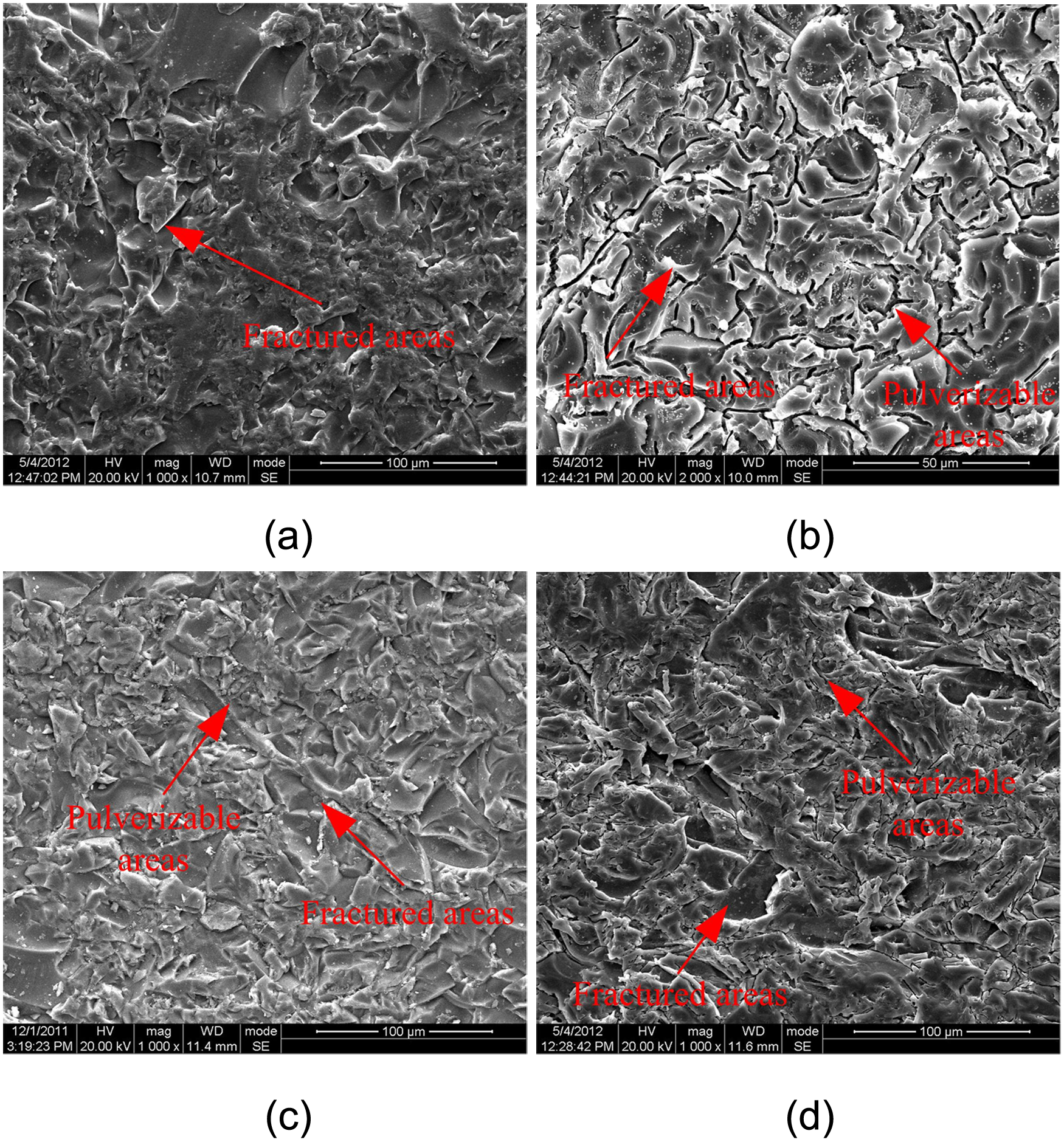
Optical micrographs of K9 glass produced in CG and RUM processes. (a) Machined with tool 4, CG; (b) machined with tool 1, RUM; (c) machined with tool 3, RUM; (d) machined with tool 4, RUM.
The SEM observations of RUM surfaces are illustrated in Figure 4(b)–(d). Although the surfaces were formed with different diamond tools and process parameters, all the surfaces consisted of two different areas: (a) the fractured areas and (b) the pulverizable areas (as arrowed in Figure 4). In the fractured areas, the observations revealed that micro-chippings and micro-cracks prevailed on the workpiece surfaces, suggestive of the primary material removal mechanisms including brittle fracture, which were similar to that of the CG surfaces. It seemed that the ultrasonic vibration had little effect on the material removal in the fractured areas. From the micrographs, it was obvious that the pulverizable areas were generated on all the RUM surfaces, although its distribution largely altered with the process parameters and tools. So it was evident that pulverization was a universal phenomenon in RUM of glass K9.
To further investigate the characteristics of pulverizable areas, the magnified view of the RUM surfaces are shown in Figure 5. Different from fracture areas, finer debris, with an average size of approximately 1 µm, were observed in the pulverizable areas (as arrowed in Figure 5(a)) and concentrated together in clumps surrounded by brittle fracture areas. The tortuous cracks were only identified on the fragments in the immediate vicinity of pulverizable areas, and were about to cleave the fragments into smaller pieces (enlarged views). While, there were no tortuous cracks inspected in the fracture areas farther from the pulverizable areas, apparently, at a local level, the SEM micrographs suggested that the material was pulverized with the force of tortuous cracks propagation. A similar phenomenon was also observed on other RUM surfaces. Altogether, the SEM examinations revealed that the workpiece surfaces were generated by the combined material removal mechanisms of brittle fracture and pulverization.
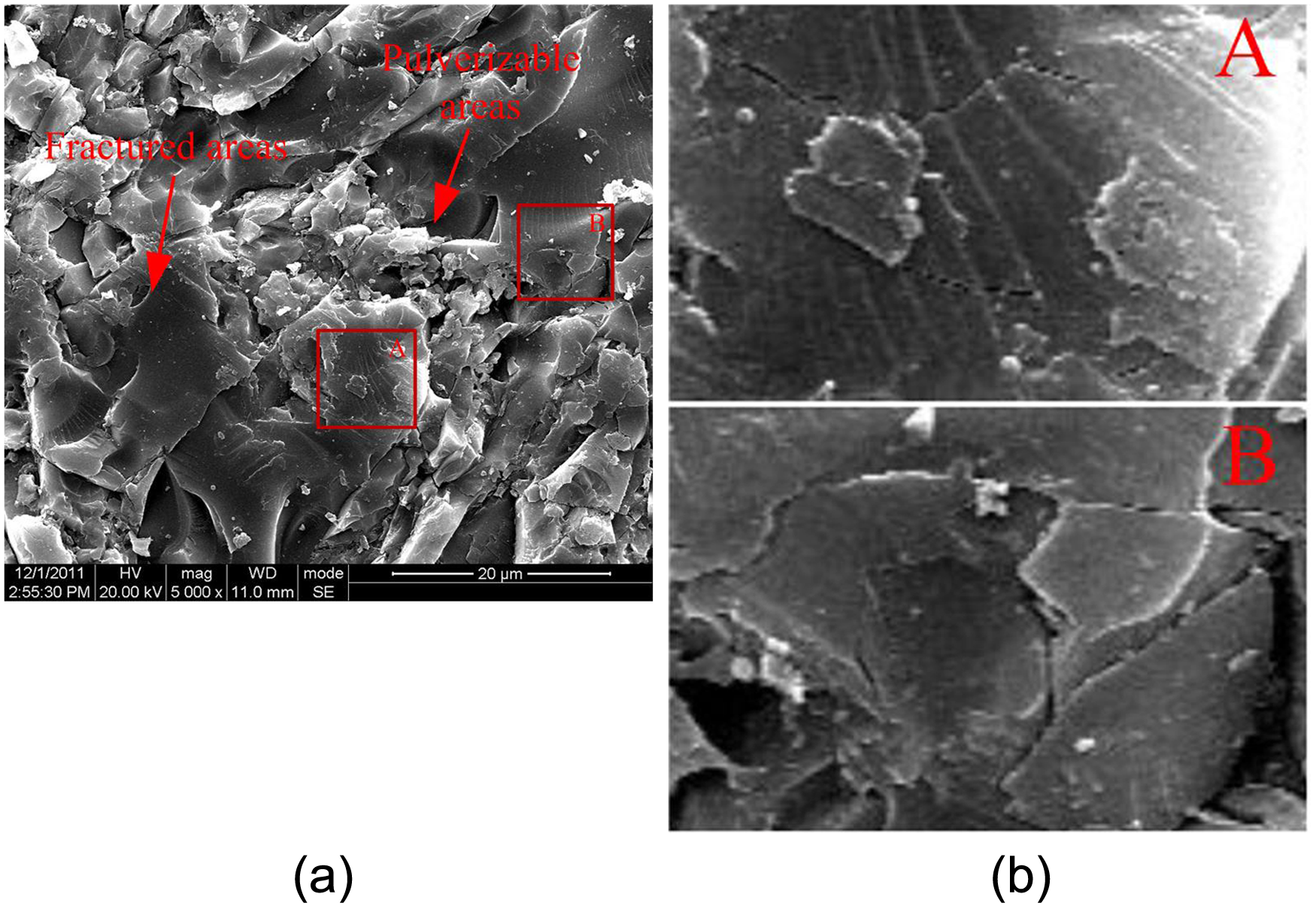
SEM micrographs of the pulverizable area: (a) machined by tool 3, RUM; (b) enlarged views, A and B.
Pulverization had also been reported in CG ceramics processes. 14 Pulverization was regarded as a consequence of intergranular and/or transgranular micro-cracking owing to a localized stress field of shear stresses superimposed by hydrostatic compressive stresses induced by abrasives. 15 Owing to the fact that the material right underneath the abrasives exhibited the maximum hydrostatic compressive stresses, from this argument, it could be concluded that the pulverizable areas should mostly be located at the bases of the RUM marks. However, the measured results of the measuring microscope depicted that the pulverizable areas were prominent in the surrounding fracture areas. This indication gave an important insight into the mechanisms of pulverization formation and material removal.
Formation mechanisms of pulverization
The scratched surface produced in test 2 is presented in Figure 6. At the inception of the scratching surface, the scratched marks induced by different abrasives could be separately differentiated. As the cutting depth increased, the scratches of different abrasives generally overlapped with each other. To obtain the details of the scratches, the local enlarged morphologies of the scratches, which were inspected by a measuring microscope and white-light interferometer, are shown in Figure 7. Each scratch consisted of a succession of grooves. Both scale-like cracks and plastic flow of the material were identified on each groove surface of scratch 1 and 2, which indicated that the material was removed in a ductile–brittle transition regime.
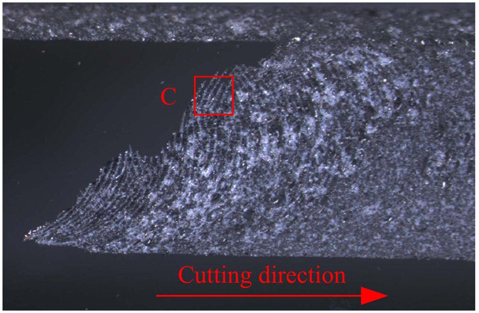
Optical micrographs of K9 glass scratched in test 2.
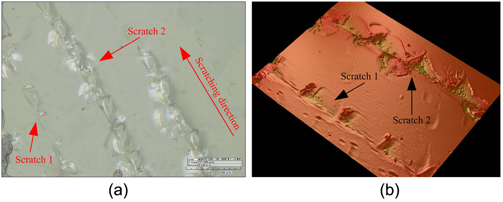
Examination results of view C using a measuring microscope and white-light interferometer. (a) Optical micrograph of enlarged view C; (b) Veeco micrograph of enlarged view C.
It was generally known that, as the cutting depth increases, after the critical stress is exceeded, the cracks began to emerge on the workpiece surface during the machining of brittle materials process. In this case, the first cracks should generate at the bottom of each groove where the most depth of cut was obtained. Incompatible with this common sense, by comparing the sinusoidal trajectory of the abrasive (shown in Figure 2) and the groove morphology, it was found that the isolated cracks first emerged nearby the vertex of the trajectory, rather than the deepest point of each groove. This phenomenon was confirmed in scratch 2, where the conchoidal cracks generated at the top point of the abrasive path were much more than those in other places on each groove. This could be owing to fact that, in each ultrasonic vibration cycle, the local contact stress reached the maximum at the vertex of sinusoidal trajectory of the abrasive, leading to the nucleation and formation of the first cracks seen in Figure 7. The reason for this phenomenon will be explained in the ‘Discussion’. However, after exceeding the top point of the abrasive path, the crack propagations did not occur as the cutting depth increased. This could be interpreted as the tensile stress produced by the extrusion, between the abrasive and the workpiece, was insufficient to make crack propagation. Sub-sequently, the material went into a plastic deformation stage, as shown in Figure 7.
Owing to the specific energy requirement for the crack propagation being lower than that in normal chip formation, 16 it could be inferred that when the cutting depth was large enough, the first cracks would spread forward with the moving ahead of the abrasives. Subsequently, when the first cracks reached the workpiece surface, the material would be removed by conchoidal fractures. This fact led to the conclusion that the pulverization (see ‘Surface characteristics and material removal mechanisms’) was induced by the impact of the abrasive at the vertex of the sinusoidal trajectory, where the maximum contact stress was obtained. These promotions were coincident with the surface characteristics; the pulverizable areas were prominent in the surrounding fracture areas that were formed by the spreading of the first cracks, as mentioned in ‘Surface characteristics and material removal mechanisms’.
In addition to the surface morphology, surface roughness was also an indicator to characterize the material removal mechanisms associated with the RUM process. For a given ultrasonic vibration frequency, the distribution of the pulverizable areas changed with the variation of process parameters, which, as a consequence, resulted in the changing of the surface roughness.
Surface roughness
The directionality of average surface roughness Ra of the RUM surfaces produced in test 3, together with the lower and upper limits among the seven measurements, ae illustrated in Figure 8. The Ra values versus the spindle speed are plotted in Figure 8(a). It was seen that Ra perpendicular to the feed direction increased with the increasing spindle speed, while that parallel to the feed direction was not sensitive to the spindle speed increasing. This may be interpreted as: the increasing spindle speed resulted in the abrasive engaging more often at equal frequency during each tool rotation cycle. Therefore, as discussed in ‘Surface characteristics and material removal mechanisms’, less pulverizable areas were induced, whereas the fracture areas were expanded. In addition, the pulverizable areas were prominent from the surrounding fracture areas, which was important in determining Ra. Therefore, Ra perpendicular to the feed direction varied more seriously than that parallel to the feed direction.
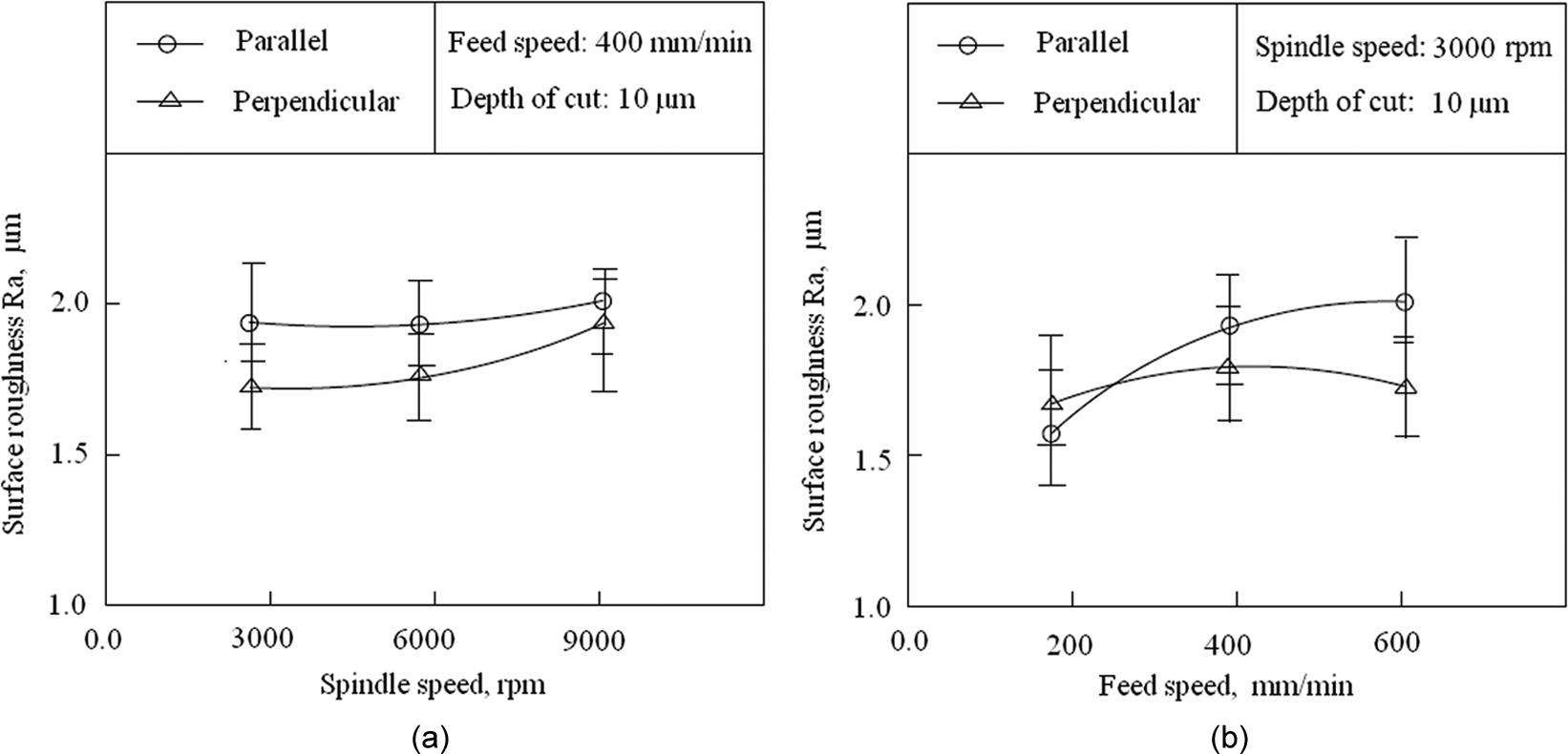
Surface roughness Ra versus (a) spindle speed and (b) feed speed for K9 glass.
At cut depth of 10 µm, the increasing feed speed resulted in a larger Ra parallel to the feed direction (Figure 8(b)). Whereas, the surface roughness Ra perpendicular to the feed direction was slightly changed. This phenomenon could be explained by two aspects. First, for each abrasive located on the tool end face, the increased feed speed led to greater penetration of the abrasive into the material in the feed direction, which caused a larger cutting force and thus worse surface finish; namely, the larger Ra value was obtained. Furthermore, the trace distance of the neighbor abrasives was enlarged, which also resulted in a rougher surface. However, for a certain ultrasonic vibration frequency and rotation speed of the tool, the chance of the abrasive engagement was not varied; namely, the distribution of the pulverizable areas was essentially the same. So the surface roughness Ra, parallel to the feed direction, was slightly changed.
Discussions
The SEM examinations of the RUM surface characteristics shown in ‘Surface characteristics and material removal mechanisms’ indicated that the material removal of K9 glass was mainly owing to brittle fracture and pulverization. Based on the observations of the scratching surface generated in test 2, the early stage for pulverization was the nucleation and formation of the first cracks. Chandra et al.
17
and Chen et al.
18
respectively demonstrated that the dynamic fracture toughness, provoked by the high speed and the strong impulse when the abrasive came in contact with the workpiece, was the main reason for the difference in performance in the high speed CG process. However, the abrasive continuously contacted with the material in test 2, and the instantaneous speed was only 1.348 m/s at the vertex of the sinusoidal trajectory (as shown in Figure 2). It should be noted that the maximum absolute value of the acceleration (closer to

where
In the cylindrical coordinate system, the defects or micro-cracks, induced in the previous machining processes beneath a diamond abrasive, could be described as an elastic solid containing a planar slit crack of finite length
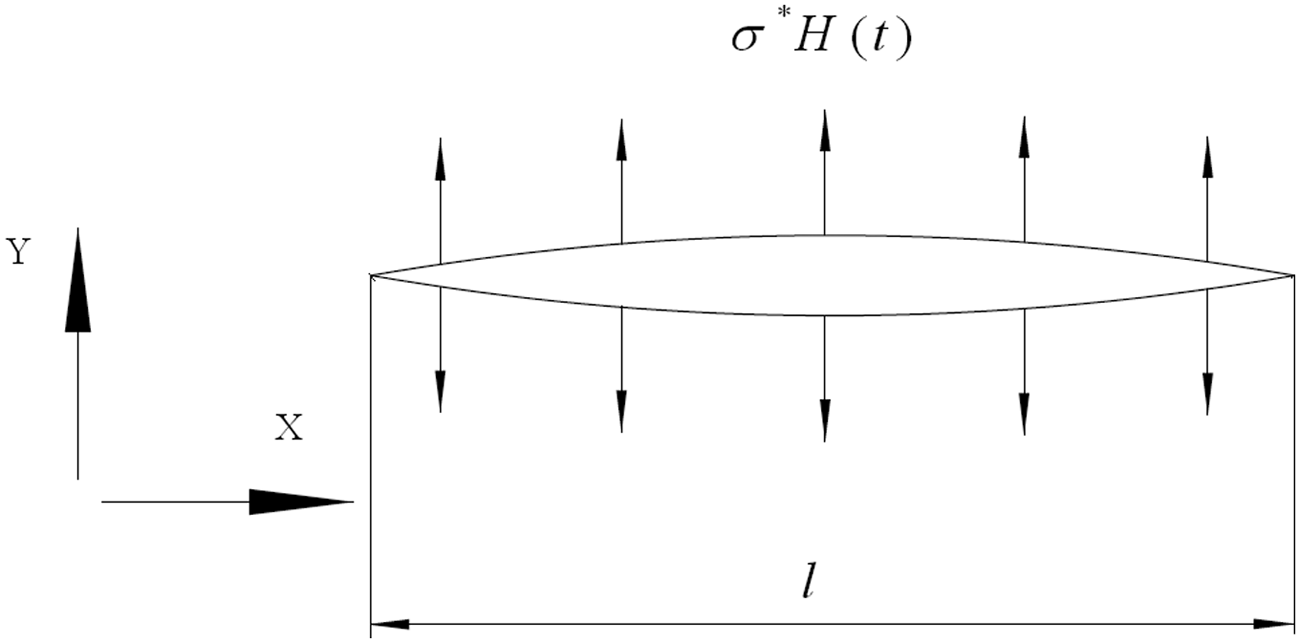
A crack of finite length

where
Second, the impulse-like loading

For most materials, including the glass, owing to strain-rate effects, the dynamic fracture toughness
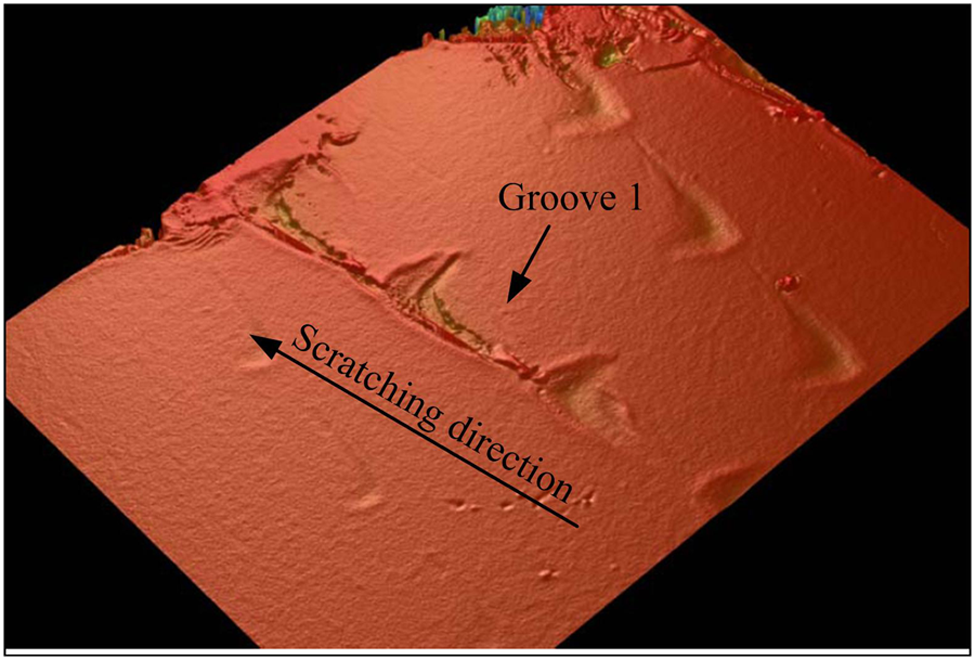
Veeco examination result of a scratch generated with tool 2.
Based on the information obtained in this research, it could be concluded that, under the impact of the vertical inertia force at the vertex of sinusoidal trajectory of the abrasive, a large number of fine cracks (pulverization) were first produced. Subsequently, as the reduction of the acceleration, the stress induced by the vertical inertia force was insufficient to cause the small cracks. So, under the extrusion of the abrasive, a small number of relatively large (brittle fracture) cracks advanced to the surface causing scale-like fractures.
Conclusions
In the present study, the kinematic principles of diamond abrasives and surface characteristics of optical glass K9 were studied for exploring the mechanisms of material removal involved in the RUM process. The direct observations of RUM surfaces were selected in this investigation as they could provide key information on the material removal mechanism. The detailed conclusions were summarized as follows.
Experimental evidence presented that pulverization could be another material removal mechanism in the RUM process besides brittle fracture and plastic deformation. It was expected that, by changing the process parameters and tool variables, different proportions of the pulverizable areas were obtained.
The measuring results of the relative height between the fractured areas and the pulverizable areas revealed that the pulverizable areas were prominent in the surrounding fracture areas. The SEM micrographs of the pulverizable areas suggested that the RUM surfaces of K9 glass were pulverized with the force of tortuous crack propagation.
By comparing the optical and Veeco micrographs of the RUM grooves produced in the ductile–brittle transition stage, it was found that the first cracks emerged when the abrasive reached the vertex of the sinusoidal trajectory, while the bottom of each groove was plastic deformed. So it could be concluded that the pulverization was induced by the impact of the abrasive at the vertex of sinusoidal trajectory.
The nucleation of the first cracks should result from the great vertical inertia force of the abrasive and the inertial effects of the material, both of which were induced by the immense acceleration of a single abrasive when the abrasive reached the vertex of its sinusoidal trajectory.
The increase of the spindle speed led to a rougher surface perpendicular to the feed direction, while the surface roughness Ra parallel to the feed direction was not sensitive to the spindle speed increasing. The investigations also revealed that larger feed speeds worsen the surface finish in the feed direction. Whereas, Ra perpendicular to the feed direction was slightly changed.
Footnotes
Funding
This research received no specific grant from any funding agency in the public, commercial, or not-for-profit sectors.