
Abstract
Electrical discharge machining is a non-conventional material removal process; recently, efforts have been made to use it as a surface alloying/modifying method. This study investigates and compares the micro-hardness of the surface machined by electrical discharge machining process using composite tool electrode (copper–chromium–nickel) manufactured by powder metallurgy and conventional copper tool. Design of experiment is used to find the best level of process parameters in order to achieve high micro-hardness. The machined surfaces are subsequently analyzed using different techniques like scanning electron microscopy, X-ray diffraction and energy-dispersive spectroscopy to ascertain the surface characteristics. Results indicate that the micro-hardness of the alloyed surface formed by powder metallurgy tool electrode is improved by 96.3% as compared to base material and 65.7% as compared to the surface machined by conventional copper electrode. Energy-dispersive spectroscopy of the surface machined using powder metallurgy electrode confirms significant material migration from tool and dielectric to the machined surface. The X-ray diffraction shows the formation of cementite (Fe3C), intermetallic compound of iron, chromium and nickel (FeCrNi) and chromium carbide (Cr7C3) on the surface machined using powder metallurgy electrode.
Keywords
Introduction
Hot die steels are high-strength steels, widely used for hot working tools like forging dies, hot piercing punches, forming punches and extrusion dies. Because of their extensive and frequent use, tools or dies made of it often encounter problems such as corrosion, high temperature surface oxidation and wear. Hence, to improve the performance of the component and to enhance life cycles without losing the intrinsic properties of the material, surface modification is required. Conventionally, surface modification techniques like chromium plating, carburizing, nitriding, chemical vapor deposition (CVD)/physical vapor deposition (PVD), plasma arc spraying and ion beam techniques are used. 1 These are secondary processes which require expensive equipments and add to the manufacturing cost and time.
Electrical discharge machining (EDM) is a non-traditional machining process used widely for machining of dies, punches and other press tools. In EDM, the electrical energy is converted into thermal energy through a series of discrete electrical discharges between the electrodes (tool and workpiece) with opposite polarity immersed in a dielectric fluid. The discharge of the capacitor in the circuit initiates a spark by creating a plasma channel at the point of smallest inter-electrode gap that results in dielectric breakdown. During the pulse on-time, the electrical energy released by the generator generates a very high temperature of the order of 8000 °C to 12,000 °C, 2 resulting in local melting and partial vaporization of the tool electrode and the base material at the point of discharge. At the end of pulse on-time, the plasma channel collapses and the circulating dielectric carries away most of the vaporized material and cools the surfaces. However, molten metal from the tool and the constituents of the dielectric get resolidified on the base material and the tool electrode. 3 This attribute of material transfer is helpful in surface alloying of the base material by EDM. Many researchers have reported the feasibility of surface modification using EDM and called it “electrical discharge alloying (EDA).” Furthermore, Roethel and Garbajs 4 observed that the properties of the machined surface depend on the alloys and phases formed in the modified surface layer due to the diffusion of material from tool electrode and breakdown of the dielectric.
Literature review
Many methods are reported to improve a particular surface property by alloying the workpiece surface with suitable elements using EDM. Researchers have used sintered or semi-sintered powder metallurgy (PM) electrode,5–7 powder suspended in a dielectric fluid8–11 and suitable dielectric fluid 12 for surface alloying. Research is going on to investigate the performance of tool electrode manufactured by PM process. Mohri et al. 13 used composite electrodes made of tungsten carbide, copper, aluminum and titanium to modify aluminum and carbon steel. The generated surfaces had fewer cracks with higher corrosion and wear resistance than the base metal. Fine dendritic precipitates of titanium carbide (TiC) were observed when powder compact electrodes made of 64% Ti and 36% Al were used to modify the surface of aluminum. 14 Li et al. 15 used TiC/Cu/W liquid-phase sintered tool and observed increase in material removal rate (MRR) and tool wear rate (TWR). Simao et al. 16 compared the performance of green compact and fully sintered PM tool electrodes made of TiC/WC/Co and WC/Co and reported an increase in the white layer micro-hardness (MH) up to 950 HK0.025 when former electrode was used. The presence of W, Co and C in the alloyed layer formed by machining 2% Cr steel with WC/Co, W/CrC/Co and TiC/WC/Co tool increased the surface hardness by 100%. 17 Bai and Koo 18 reported a strongly adhered alloyed layer of thickness about 40–50 µm using Al-Mo composite electrode. Furthermore, Chen et al. 19 found that use of semi-sintered electrodes could generate a significant thick modified layer (180–210 µm) in a very short machining time (about 600 s). Hwang et al. 20 studied electric discharge coating (EDC) by multi-layer electrodes (MLEs), composed of alternately stacked layers of graphite (Gr) and titanium (Ti), to generate titanium carbide (TiC) layer on the surface of nickel workpiece. It was observed that high concentration of carbon (C) element could increase the integration of Ti and C to TiC. The process enhanced the surface hardness and decreased the surface roughness of the coated layer. It also reduced the formation of micro-cracks and enhanced the stability of electric discharge and coating speed. A successful attempt was made by Ndaliman et al. 21 to enhance the surface MH of a titanium alloy through modification using composite tool electrode (Cu-TaC) and urea solution as dielectric. Maximum MH was attained when Cu-TaC tool was used with urea solution of 10 g/L concentration. Suzuki and Kobayashi 22 investigated the mechanism of formation of titanium carbide layer using TiC powder electrodes in single-pulse discharges in EDM. Adhesion of TiC from electrode to the workpiece was compared to that with the already generated TiC layer on the workpiece surface due to consecutive EDC process. It was observed that the amount of TiC adhesion to the workpiece material was larger than that to TiC layer. Hence, an increase in the thickness of TiC layer was noticed in the beginning of the EDC process. However, no further increase in layer thickness was observed with increase in process time due to a balance of TiC adhesion and removal. Chen et al. 23 explored wet and dry EDC of an aluminum alloy (6061-T6) using sintered Ti electrodes of different densities. Comparison of the results revealed that both MRR and TWR were much lower in dry EDC than in wet EDC. However, no titanium nitride (TiN) layer was formed during the later process. On the other hand, negative MRR and TWR were observed in dry EDC with anodic sintered electrodes. A pure TiN layer (20-µm thick) with good spallation resistance was deposited on the electric discharge coated surface. Gill and Kumar 6 studied alloying of a die steel surface using Cu-W sintered tool electrode. Significant increase in percentage of tungsten and carbon was reported along with the formation of tungsten carbide under favorable conditions for alloying. Ahmed 24 deposited a ceramic coating on the surface of aluminum using green compact tool made of titanium, boron carbide and aluminum (Ti + B4C + Al) through EDM process. Cogun et al. 5 investigated the capability of Cu-B4C composite electrode to alloy the surface during EDM with boron and other intermetallic phases. The presence of various phases such as FeB, B4C and Fe3C in the alloyed surface was reported. It was concluded that formation of these compounds had significantly enhanced the hardness and wear resistance of the machined surface.
While studying the effect of EDM process parameters on the performance of PM electrodes, it was found that these electrodes are more sensitive to peak current and pulse duration than conventional solid electrodes. 25 Peak current was the most important machining parameter affecting both MRR and TWR, while flushing pressure had little effect on both the responses. 26 The performance of these tools in EDM also depends on PM tool manufacturing parameters like powder particle size, sintering temperature, sintering time and compacting. Lower material migration rate and modified layer thickness were observed when high compacting pressure and sintering temperature were used for tool manufacturing. 27 It was due to firm bonding in tool materials.
According to the available literature, researchers have investigated the feasibility of altering the surface properties due to material transfer during EDM. Most of the researchers have used PM electrodes for surface modification by coating. However, exhaustive experimental analysis is still required for the practical applicability of surface alloying using PM electrodes in EDM. Furthermore, literature related to surface alloying of commonly used die steel with different steel alloying elements is still missing. Lot of investigation is required to find the optimal set of parameters for enhancing surface properties like MH and surface finish. The surface properties also depend on the compounds formed by alloying elements during machining. Hence, they also need a detailed experimental investigation.
In this study, an effort has been made to investigate the surface MH of hot die steel (H11) using tool electrode manufactured by PM process for surface alloying through EDM. The alloying elements for tool steels are classified as ferrite stabilizers (Cr, W, Mo, V and Si) and austenite stabilizers (Mn, Ni, Co and Cu). The austenite phase may not appear in steel at any temperature when sufficiently large quantities of ferrite stabilizers are added. Such steels do not have austenite phase for solid–solid phase transformation. On the other hand, it is possible to reintroduce austenite phase in such steels by addition of austenite stabilizers. Therefore, a balance of both ferrite and austenite stabilizers is required for ideal alloying. In this study, chromium and nickel are selected as alloying elements. Chromium is one of a carbide and pearlite promoting elements. It promotes the formation of carbides containing chromium, which increases surface hardness and corrosion resistance. 28 On the other hand, nickel is an austenite-stabilizing element that reduces the temperature of γ-α transformation. It has a capability of solid solution strengthening in ferrite phase. Addition of 1% nickel leads to an increase in yield strength by 40 MPa and hardness of ferrite by 15 HB. 28 The ability of chromium to improve hardenability and wear resistance can be combined with that of nickel to increasing toughness and ductility by alloying the die steel with both nickel and chromium together. However, the concentration of these alloying elements cannot be kept high in the base metal as it affects the heat treatment behavior of die steels. Therefore, these are desirable as alloying elements in the machined surfaces only. L18 orthogonal array (OA) of Taguchi experimental design is applied to plan the experiments. The effect of six process parameters on MH is investigated. The performance of PM electrode is compared with the conventional copper tool electrode. Analysis of variance (ANOVA), a statistical tool, is used to analyze the contribution of these parameters toward MH. Scanning electron microscopy (SEM), energy-dispersive spectroscopy (EDS) and X-ray diffraction (XRD) of the machined surface are evaluated to investigate the surface alloying.
Experimentation
In this study, tool electrodes made by PM process and conventional copper (electrolytic 99.9% pure) of same geometry are used for conducting experiments. The PM tool electrodes are made of electrolytic copper powder (99.8% pure) mixed with alloying elements (equal amount of chromium and nickel) powder (99.8% pure). Table 1 gives the properties of the powders used. The metal powder is mixed with zinc stearate (1% by weight) using a V blender. The mixture is blended for 60 min at 35 r/min. The cylindrical shaped electrodes are prepared by compacting the powder mixture. Details of PM process are given in Table 2. Figure 1 shows the PM tool electrodes used in the experimentation.
Properties of powders.
Compacting and sintering specifications.
PM tool electrodes used in experimentation.
Hot die steel, H11, is selected as a workpiece material. Before starting the experiments, work material is subjected to the standard hardening and tempering cycle. 29 Table 3 gives the composition of workpiece. Microstructure of the hardened and tempered workpiece material is shown in Figure 2. It shows a uniformly distributed spheroidal cementite in the tempered martensite matrix. Before machining the workpiece, the MH is tested at six different locations, and the average value comes out as 705.5 HV.
Chemical composition of workpiece material.
SEM micrograph of the original microstructure of H11 workpiece.
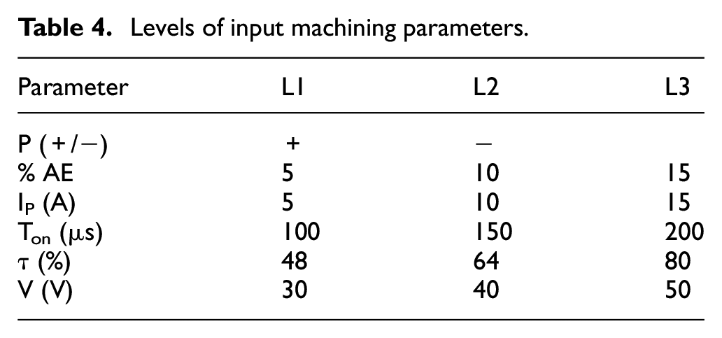
Six process parameters chosen for the experimentation with PM tool electrode and their selected levels are listed in Table 4. For experimentation with conventional copper electrode, the process parameter, percentage of alloying element is excluded from the list. Machining time for each experiment is 10 min.
Levels of input machining parameters.
Taguchi’s experimental design is used for designing the experiments. The final L18 OA listing the 18 experimental set of parameters using PM tool electrode is given in Table 5. The same L18 OA is used for experimentation with conventional copper electrode by keeping the second column of OA (i.e. % AE) as dummy. By comparing the signal-to-noise (S/N) ratio of the observed values of MH, the optimal combination of the machining parameters is determined.
Orthogonal array L18 matrix with results of micro-hardness.

MH: micro-hardness.
The experiments are performed on a die-sinking EDM machine (Elektra EMS 5535) of Electronica Machine Tools (India). Each machined surface is measured for MH thrice. To examine the MH of the machined surface, Vickers MH testing machine under the testing condition of 50 g load applied for 20 s is used. The machined samples are examined by a field-emission scanning electron microscope for surface morphology and chemical composition changes. An X-ray diffractometer system is used to ascertain the phases formed on the machined surface. The range of 2θ for the XRD analysis is selected from 30° to 100°.
Results and discussion
Three measurements of MH are taken on each machined surface, and their mean values are given in Table 5. MH is the higher-the-better type of response parameter. To find set of parameters that give best MH, the S/N ratio is calculated from the experimental data. It is given by
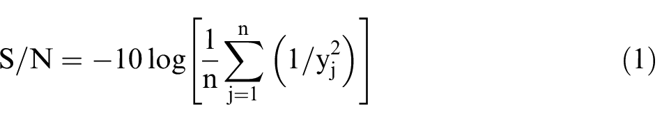
where yj is the observed value of the MH and n is the number of reruns.
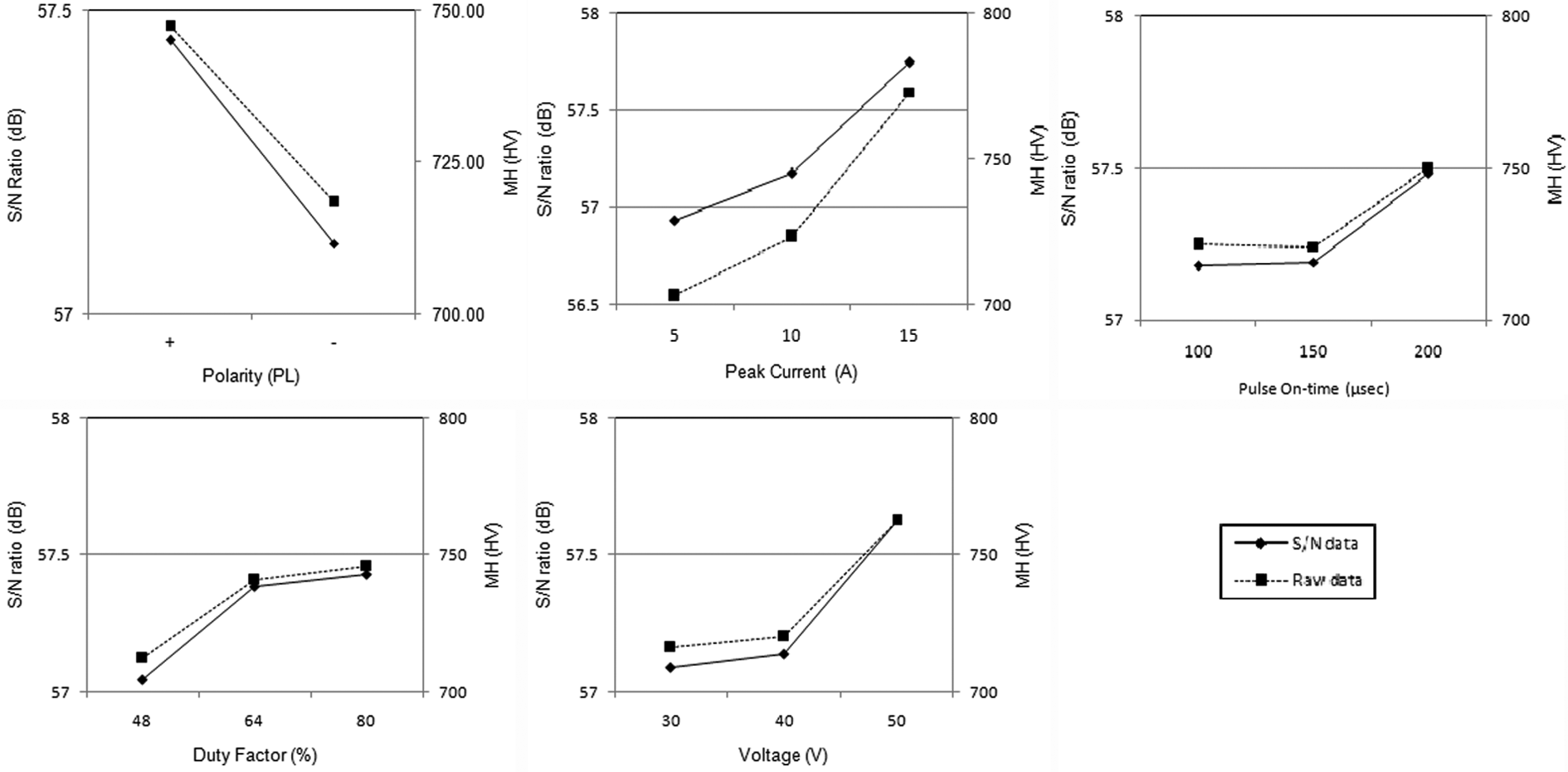
The calculated values of S/N ratio for MH are presented in Table 5. The average values of MH and the corresponding S/N ratios at different levels of the process parameters are calculated to find out the control factors’ effect. These values are shown in main effect plots for MH when machined with PM tool electrode and conventional copper tool electrode in Figures 3 and 4, respectively. Based on the experimental results, the influence of the machining parameters is discussed hereafter.
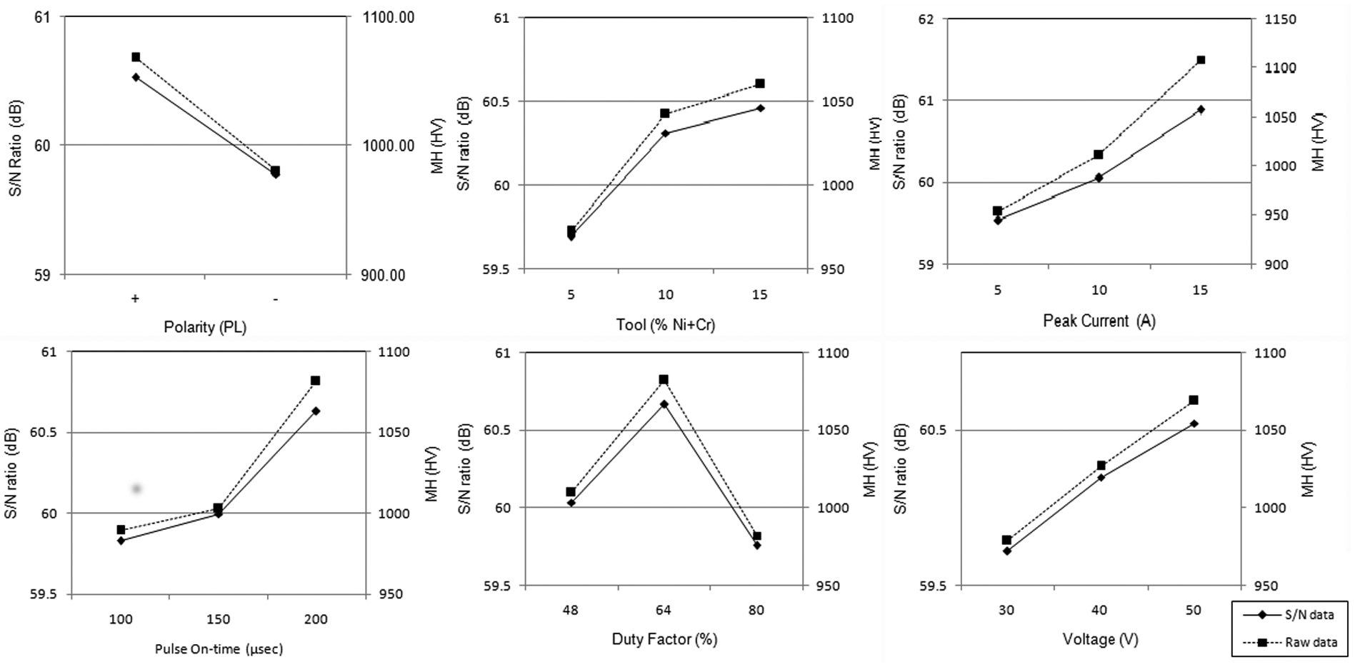
Main effect plots for MH when machined with PM electrode.
Main effect plots for MH when machined with conventional copper electrode.
Effect of tool polarity
The tool polarity has a significant effect on MH. It is observed that reverse polarity gives the higher MH irrespective of the type of tool electrodes. The result is well supported by the fact that the discharge spot on the anode is larger than that on the cathode, 30 and the energy density of the anode is less than that of cathode under the same working conditions. 31 When PM tool electrode is used with negative polarity, it experiences high wear due to larger energy density than that on the workpiece. As a result, larger amount of material drops on the workpiece surface. However, the dropped material does not get mixed effectively with the shallow molten surface because of low energy density on the anode workpiece. The shallow molten surface re-solidifies quickly without forming an effective alloyed layer. When the conventional copper tool with positive tool polarity is used, the increase in MH can be attributed to high energy density on negative workpiece resulting in more heating during pulse on-time and quenching during off-time.
Effect of alloying element percentage in tool
Tool with 15% AE gives best MH. The increase in concentration of chromium and nickel in PM tool electrode increases the MH. Higher MH is related to higher alloying, change in composition of the recast layer and formation of new compounds (carbides of chromium). This factor is not considered when conventional copper tool electrode is used.
Effect of peak current
It is observed that MH increases with peak current irrespective of type of tool electrode used. The trend is due to increase in discharge energy with increasing peak current; it causes more heating and quenching during the process.
Effect of pulse on-time
It has been observed from the main effect plots that MH increases as pulse on-time increases from level 1 to level 3 in both cases, that is, machining with PM tool electrode and conventional copper tool electrode. With the increase in pulse on-time, the discharge energy of the plasma channel and the period of conducting heat into the electrodes increase. This phenomenon causes the increase in the alloyed layer thickness in case of machining with PM tool electrode and white layer thickness in case of conventional copper tool electrode.
Effect of duty factor
High level of τ reduces the off-time between two consecutive discharges. While using PM tool electrode, the contamination of machining zone is higher due to low binding strength of the tool material as compared to conventional solid copper tool electrode. Hence, at 80% duty factor, the short pulse off-time does not give enough time required for recovery of dielectric strength and induces arcing or unstable sparking. Also, the molten zone does not get enough idle time to cool down and absorb the products of sparking. Therefore, the carbon and alloyed layer formed gets flushed out from the workpiece. High MH is observed at moderate level of duty factor when PM tool electrode is used. In case of machining with conventional copper electrode, 80% duty factor gives a stable discharge due to low contamination of discharge gap.
Effect of discharge voltage
The spark energy increases with discharge voltage. Hence, in case of both the types of tool electrodes (PM and conventional copper), MH increases with discharge voltage.
Theoretically, positive tool polarity (A1), tool with 15% AE (B3), third level of peak current (C3), third level of pulse on-time (D3), second-level duty factor (E2) and third level of discharge voltage (F3) give the highest MH when PM tool electrode is used. Similarly, positive tool polarity (A1), third level of peak current (C3), third level of pulse on-time (D3), third-level duty factor (E3) and third level of discharge voltage (F3) give the highest MH when conventional copper tool electrode is used.
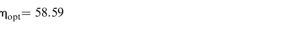
Under the best conditions for response parameter (MH), the theoretical value of S/N ratio (ηopt) is calculated by
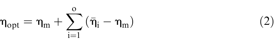
where
ηopt for MH when machined with PM tool electrode using the optimal level of the design parameters (A1B3C3D3E2F3) is given as

And corresponding value
ηopt for MH when machined with conventional copper tool electrode using the optimal level of the design parameters (A1C3D3E3F3) is given as
And corresponding value
The suggested set of parameter, in case of using PM tool electrode, does not exist in the OA. Hence, the set of parameter is used to perform confirmation experiments. Average surface MH when machined with PM tool electrode at A1B3C3D3E2F3 is found to be 1385.2 HV. In case of machining with conventional copper tool electrode, the combination of input process parameters (A1C3D3E3F3) does exist in the OA at third row. The average value of MH obtained at this setting of the experiment is 835.5 HV. The results are close to the theoretical value predicted by Taguchi analysis. The surface machined with PM tool has higher MH as compared to the surface machined with conventional copper. It can be due to alloying/modification effect produced by material migrated from PM tool. The zone-wise variation of average MH for both samples generated in the confirmation experiments are shown in Figures 5(b) and 6(b). From top to bottom of the resolidified layer, a decrease of 13.1% in MH can be seen when PM tool is used. Whereas, negligible change is observed in case of sample machined with conventional copper tool. The reason of higher difference in former case can be the decrease in alloying elements (Cr, Ni and C) concentration with depth. However, in later case, the hardened resolidified layer is generated due to quenching effect produced by dielectric in off-time, and this effect does not vary much with depth of resolidified layer (10 µm). The MH of heat-affected zone is approximately same in both the samples. The heat-affected zone shows higher average MH value than base material due to metallurgical transformation produced by heat without melting the material.
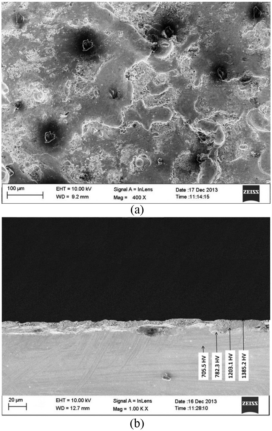
SEM micrograph of (a) machined surface and (b) recast layer using PM tool electrode (tool polarity: +ve, tool with 15% AE, peak current: 15 A, pulse on-time: 200 µs, duty factor: 64% and discharge voltage: 50 V).
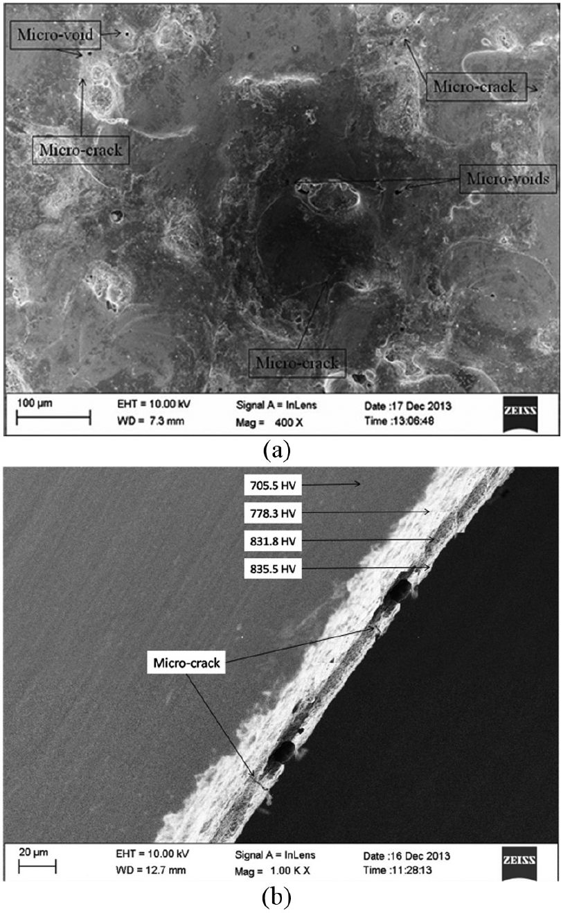
SEM micrograph of (a) machined surface and (b) recast layer using conventional Cu tool electrode (tool polarity: +ve, peak current: 15 A, pulse on-time: 200 µs, duty factor: 80% and discharge voltage: 50 V).
ANOVA is used to investigate the significance and percentage contribution of machining parameters for the observed values. The results of ANOVA for S/N of MH after machining with PM tool electrode and conventional copper tool electrode are given in Tables 6 and 7, respectively. It is observed that all the process parameters are significant and peak current gives the maximum contribution in controlling MH in both the cases.
ANOVA for S/N of MH after machining with PM tool electrode.
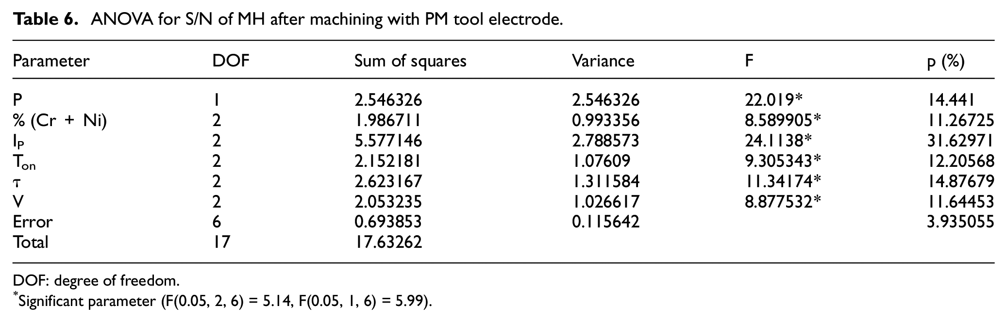
DOF: degree of freedom.
Significant parameter (F(0.05, 2, 6) = 5.14, F(0.05, 1, 6) = 5.99).
ANOVA for S/N of MH after machining with copper tool electrode.
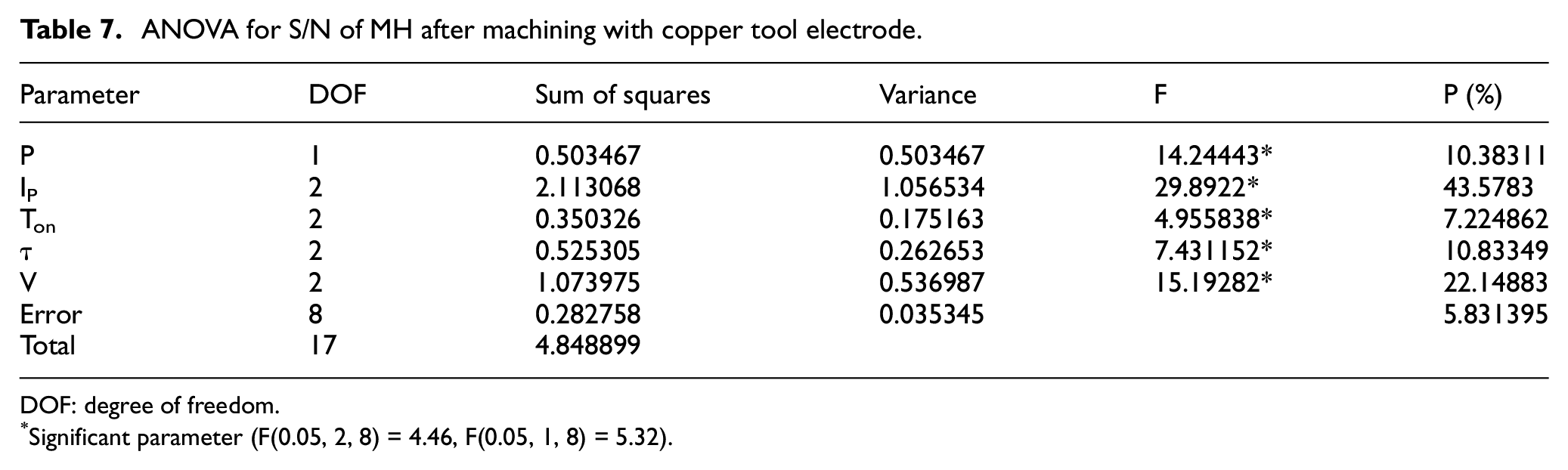
DOF: degree of freedom.
Significant parameter (F(0.05, 2, 8) = 4.46, F(0.05, 1, 8) = 5.32).
Hence, the surfaces machined using the suggested set of parameters are studied under SEM. Figures 5 and 6 show the micrograph of electrical discharge machined surface and its cross-section produced with optimal set of parameters, that is, A1B3C3D3E2F3 (best MH with PM tool electrode) and A1C3D3E3F3 (best MH with conventional tool electrode), respectively. The surface machined with PM tool electrode for best MH (Figure 5) shows rough surface. Since material drops on the surface from the tool (having low binding strength) and duty factor of 64% is used, a thick recast layer is observed. It shows the presence of discrete craters formed due to the removal of molten material. The irregular shaped particles seen on the surface are debris, that is, resolidified material that gets deposited on the electrical discharge machined surface. The morphology of the surface indicates that the material removal occurs mainly by melting during the discharge followed by its flushing out from the discharge zone by the dielectric during pulse off-time. The molten mass, which does not get flushed out during the pulse off-time, gets re-deposited on the surface. Embedded hard particles can be seen uniformly distributed in the resolidified surface. These hard particles may be formed by the combination of alloying elements from the PM tool electrode with carbon during the discharge. Their presence on the surface of in-service dies can act as crack arresters and is expected to enhance the service life. These features of the electrical discharge machined surface are also favorable for retaining lubrication. Another important observation is that the surface is crack free.
From Figure 6, it can be observed that the surface machined with conventional copper electrode have micro-cracks and micro-voids. The thermal cycles, having high heating and cooling rates, created by the discharge sparks during EDM are responsible for micro-cracks. These micro-cracks and micro-voids affect the fatigue, corrosion and other properties of machined components. As compared to Figure 5, the recast layer thickness is thin but large heat-affected zone is visible below it. This characteristic of the surface can be attributed to higher level of duty factor used in machining due to which high heat is conducted inside the workpiece and recast layer is removed.
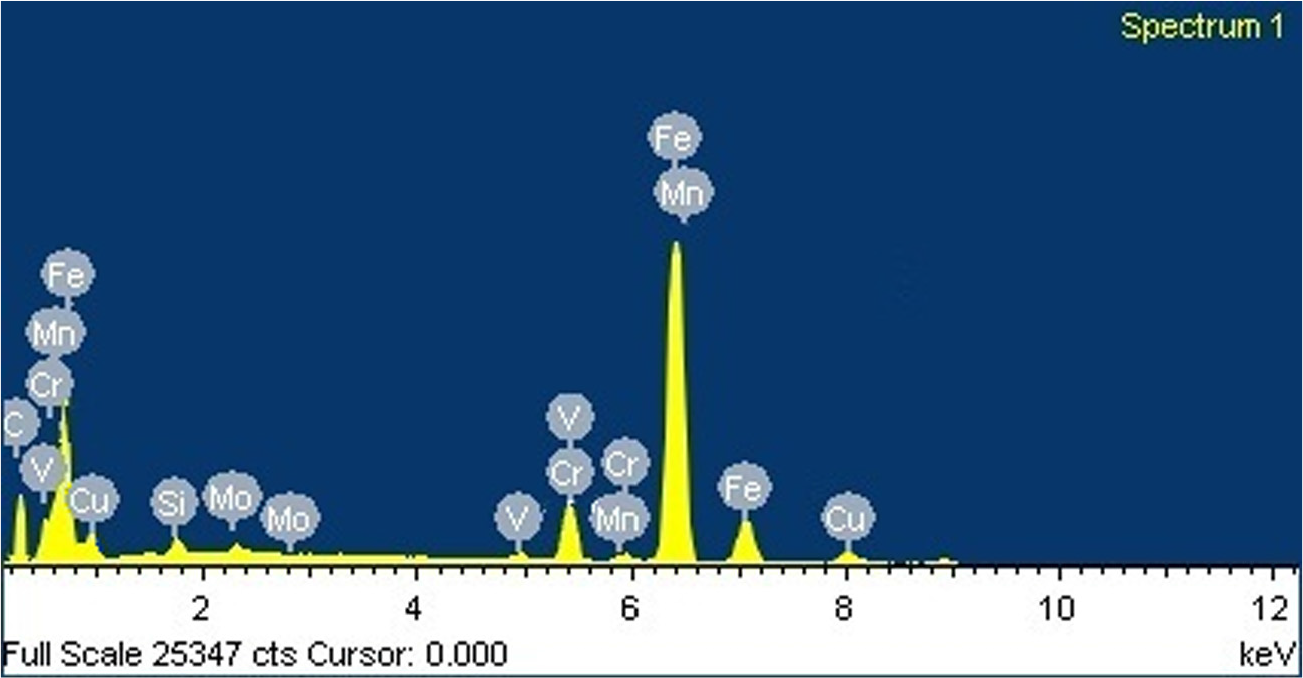
To confirm the material alloying, the surfaces machined in confirmation experiments are analyzed by EDS and XRD. Figures 7 and 8 show the EDS spectrum of the surface machined with PM tool electrode and with conventional copper tool electrode, respectively. The result shows a significant material transfer (chromium, nickel and copper) from the tool electrode to the machined surface. The composition of the machined surface is compared with that of base material of workpiece in Figure 9. The high MH can be attributed to increase in carbon content leading to cementite formation and chromium–nickel alloying to the machined surface. Chromium can also form independent hard carbides.
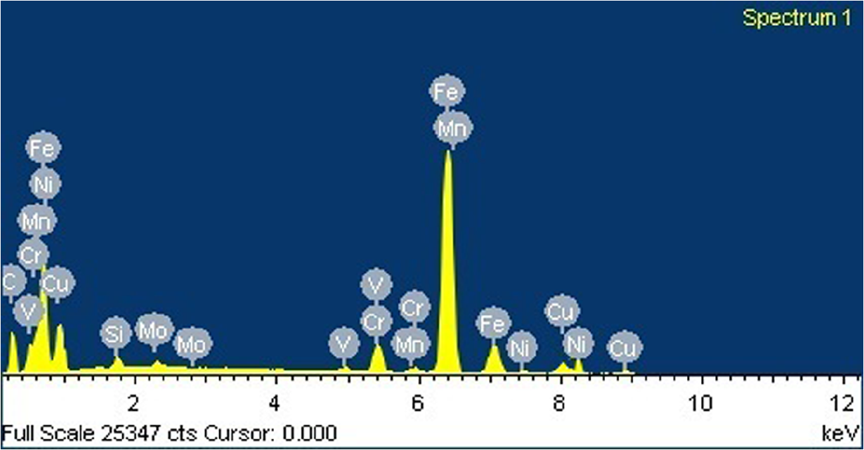
EDS spectrum of surface machined using PM electrode (tool polarity: +ve, tool with 15% AE, peak current: 15 A, pulse on-time: 200 µs, duty factor: 64% and discharge voltage: 50 V).
EDS spectrum of surface machined using conventional Cu electrode (tool polarity: +ve, peak current: 15 A, pulse on-time: 200 µs, duty factor: 80% and discharge voltage: 50 V).
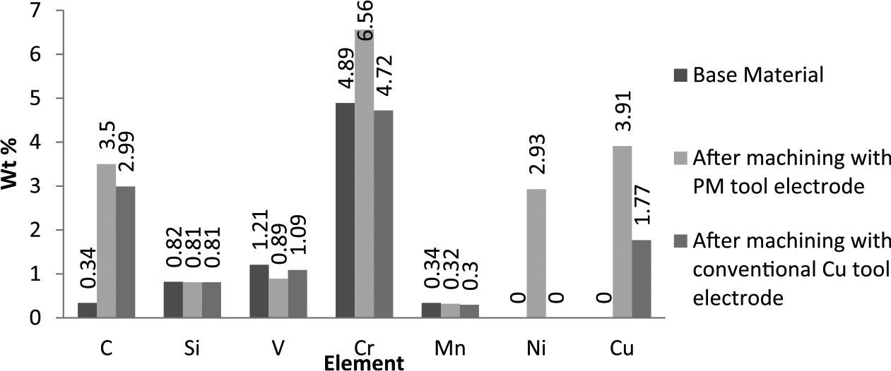
Comparison of chemical composition of surface before and after machining.
The XRD pattern (Figure 10) of the machined surface confirms the existence of chromium carbide (Cr7C3) besides cementite (Fe3C) phases and intermetallic compound of iron, chromium and nickel (FeCrNi). The high carbon content at machining zone, due to hydrocarbon dielectric breakdown, induces the formation of complex carbides in the presence of the alloying elements. The chromium carbide formed at higher temperatures is harder and more stable than cementite. Alloy carbides are formed only at high temperatures because of the lower diffusion rates of alloying elements to cause any carbide formation. These carbides play a significant role in enhancing the MH of the surface. Figure 11 shows the XRD pattern of the surface machined with conventional copper electrode. Ferrite (FeC) and chromium iron carbide (Cr, Fe)23C6 are present on the surface. Compound (Cr, Fe)23C6 is formed when part of the iron atoms are substituted by chromium atoms from a carbide of iron. It may be formed due to the presence of chromium in the base material.
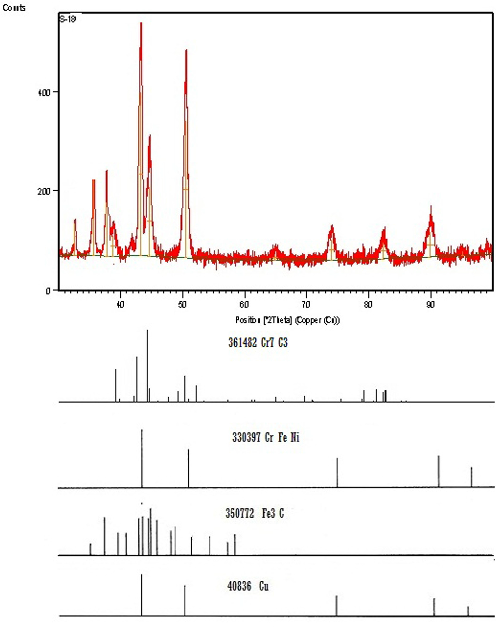
XRD pattern of surface machined using PM electrode (tool polarity: +ve, tool with 15% AE, peak current: 15 A, pulse on-time: 200 µs, duty factor: 64% and discharge voltage: 50 V).
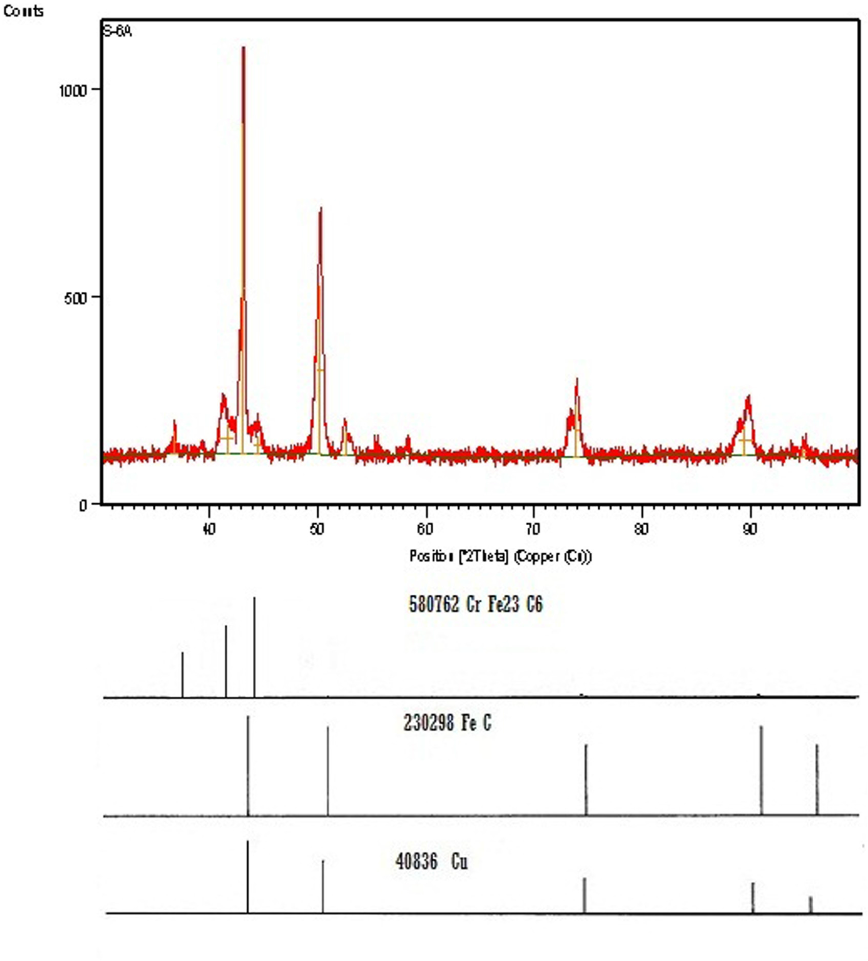
XRD pattern of surface machined using conventional Cu electrode (tool polarity: +ve, peak current: 15 A, pulse on-time: 200 µs, duty factor: 80% and discharge voltage: 50 V).
In an earlier work of surface alloying, 7 Cu-Cr-Ni PM tool was used on En31 work material. An attempt has now been made to investigate the MH of another work material (H11) with a view to study the effect of the change in material composition on the phenomenon of surface alloying. This work material has less carbon and less nickel but more chromium in its base composition. Furthermore, in this research work, this material was also machined with conventional copper electrode under similar machining conditions to draw a comparison between normal machining and machining with PM electrode. It was found that higher amount of chromium in the base material resulted in the formation of a new phase of chromium carbide (Cr7C3) which was richer in chromium as well as carbon. The phase formed by the carbide-forming element depends upon the amount of carbon and alloying element present in the solid solution. 32 Consequently, a higher value of MH was obtained on the machined surface. It is also observed that the amount of copper that can be transferred to the work material from PM electrode is more than twice the amount of copper from conventional electrode. It is well known that copper stabilizes and strengthens the ferrite phase which improves the ductility of die steel. 29 SEM micrographs show better surface integrity with PM electrode as compared to conventional copper electrode.
Conclusion
The comparative experimental research carried out in this study contributes to the generation of knowledge related to EDM technology using a PM tool electrode made of copper, chromium and nickel powders to machine H11 hot die steel. MH of the surfaces machined using PM tool electrode and conventional copper tool electrode is investigated using Taguchi’s experimental design. Tool polarity, percentage of alloying element in tool, peak current, pulse on-time, duty factor and discharge voltage are used as control parameters. The machined surfaces at the optimized level of parameters are investigated for surface alloying and other surface characteristics. Based on the results, the following set of conclusions can be drawn:
It is possible to carry out surface alloying of die steels by the EDM process. Alloyed layer having significantly high chromium (6.36%), nickel (2.93%) and carbon (3.5%) is generated using Cu-Cr-Ni PM tool electrode.
The experimental value of MH of the surface machined with PM tool electrode using optimal set of parameters is 1385.2 HV, which is quite higher than the surface machined with conventional copper tool electrode using optimal set of parameters (835.5 HV) and base material (705.5 HV).
XRD of the surface machined with PM tool electrode shows the presence of cementite (Fe3C), intermetallic compound of iron, chromium and nickel (FeCrNi) and chromium carbide (Cr7C3) which results in very high hardness and good wear resistance. These compounds are missing on the surface machined with conventional copper electrode.
No micro-crack is observed on the surfaces machined with PM tool electrode using optimal set of parameters for MH. On the contrary, micro-cracks and micro-voids are observed on the surface machined with conventional copper tool electrode using optimal set of parameters for MH. Hence, it can be concluded that surface alloying by PM tool electrode does not degrade the machined surface.
PM tool having 15% alloying element with positive polarity gives the best MH result when 15 A peak current, 200 µs pulse on-time, 64% duty factor and 50 V discharge voltage are used. The level of duty factor gets increased to 80% in the set of optimal parameters for MH when conventional copper tool electrode is used; level of other parameters remains unchanged.
Peak current is observed as the most dominating process parameter toward MH in both the types of tool electrodes.
Footnotes
Declaration of Conflicting Interests
The author(s) declared no potential conflicts of interest with respect to the research, authorship and/or publication of this article.
Funding
The author(s) received no financial support for the research, authorship and/or publication of this article.