
Abstract
In this study, the surface modification and metallurgical analysis of three commonly used die steels were analyzed by microstructure and X-ray diffraction analysis after electric discharge machining and powder-mixed electric discharge machining. The effect of many process parameters was assessed for surface modification using magnetic field–assisted electric discharge machining process. It was observed that the microhardness of the machined surface increased by more than 200%. The analysis of machined surface confirmed material migration from added powder, dielectric and electrode. The magnetic field assisted in improving the material removal process. The strength of the magnetic field resulted in better expelling of material from workpiece and restricted the material migration from electrode especially in copper-based diamagnetic material. Deposition of tungsten and titanium carbide was observed, which increased the microhardness significantly. Titanium, tungsten and graphite powder aided favorably the increase in the microhardness.
Introduction
Electric discharge machining (EDM) is one of the most commonly used nontraditional machining process wherein the electrical energy is converted to thermal energy through a series of sparks. Very high temperature generated during sparking is sufficient to melt and vaporize the material from both the electrodes in the form of tiny craters. Overlapping craters result in material removal from the workpiece in a shape which is a mirror image of the tool profile. In the recent past, some modifications in the process, such as addition of powders in dielectric, have been reported to improve the process efficiency. This process of mixing powder with dielectric is termed as powder-mixed electric discharge machining (PMEDM) and has been widely studied. The powder(s) mixed in the dielectric changes the sparking pattern, thus altering the properties of the machined surface significantly. During PMEDM, under suitable process conditions, some constituents from the electrode, added powder or the dielectric may migrate and deposit on the machined surface either in free form or in combined form to form carbides (combining with carbon due to the breakdown of hydrocarbon dielectric). This phenomenon has been reported to improve the machined surface properties as well as improve the material removal rate (MRR) and lower the tool wear rate (TWR).
Many experimental studies were reported for control, optimization and selection of process settings during EDM/PMEDM for enhanced material removal, reduced tool wear and surface roughness (SR) with improved surface properties. Detailed review of the experimental investigations and recent research trend of using powders or additives mixed in dielectric for surface modifications was summarized. 1,2 Different types of powders mixed in dielectric and their concentration along with optimal process settings create desirable machining conditions that improve the quality of the machined surface. 3 The effect of addition of different powders such as graphite, aluminum, tungsten, silicon and titanium carbide was reported for improving machining efficiency for various graded die steel workpieces. 4 –10 The addition of powder particles beyond a certain concentration reduces the effective inter-electrode gap and leads to arc formation. Material transfer from tool (material Cu, Cu-Cr, Cu-W) and suspended tungsten powder was studied for D3 die steel. 11,12 The mechanism of material migration from the hydrocarbon dielectric, tool material and suspended powder was investigated to identify the reasons for improved surface integrity. 12 –14 Multi-objective optimization of EDM/PMEDM process was reported to achieve improved process control. 7,15,16
Some recent modifications reported during EDM have been to use external magnetic field around the electrodes. The magnetic force–assisted EDM helps in expelling debris from the machining zone and thus helps to attain higher machining efficiency and surface integrity. 17 –19 During EDM, some melted metal resolidifies and settles on the workpiece and use of magnetic force helps to remove this material thereby increasing the machining efficiency. The effect of magnetic field on removal of molten metal (ferrous) from the machining zone has been studied. 20 Magnetic force–assisted EDM helps maintain uniform discharge waves by gap cleaning which increases the erosion volume in conventional, micro- and dry EDM. 21 –24 Lower recast thickness layer was observed in case of magnetic force–assisted EDM along with regular discharge waveforms due to better gap cleaning. 25,26
The review of literature shows many studies conducted for conventional EDM, PMEDM and magnetic field–assisted EDM. The effect of magnetic field with conventional EDM is established in these studies, but no studies have documented the effect during PMEDM. This study has been undertaken with an objective to establish the material migration and metallurgical aspects of the machined surface during PMEDM with magnetic field. Also, a comparative study of surface modification during EDM and PMEDM with and without use of magnetic field may provide a valuable insight into the process behavior. The surface modifications and metallurgical analysis of machined surfaces were also analyzed using scanning electron microscope (SEM) and X-ray diffraction (XRD) to quantify the material transfer.
Materials and methods
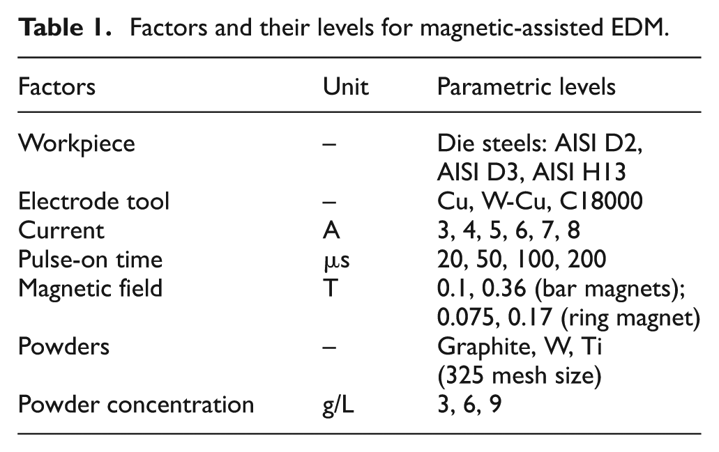
This study was undertaken with an objective to analyze the surface modification of the machined surface during magnetic field–assisted EDM with and without powder mixing. Detailed pilot study along with literature survey was conducted to identify the process parameters. The factors and their respective levels were chosen based on the settings available on the machine as well as to ensure efficacy of the machining process. For example, the maximum level of the current and powder concentration was chosen so as to prevent arcing. Similarly, the lower levels were chosen to ensure adequate material removal. The bar and the ring shape of the magnet were chosen so as to provide magnetic field in all directions. The strength was selected considering the ease of placing and removing the magnet around the workpiece. The other factors were selected based on previous studies conducted by the authors and pilot studies. 8,9,13 –16 Experiments were conducted on three common graded die steel materials, namely, AISI D2 (modulus of elasticity E = 209.9 GPa, linear coefficient of thermal expansion CTE = 11.2 µm/m-°C, thermal conductivity K = 20 W/m-K); AISI D3 (E = 207 GPa, CTE = 10.7 µm/m-°C) and AISI H13 (E = 210 GPa, CTE = 12.6 µm/m-°C, K = 25 W/m-K). Two different magnets, that is, bar and ring shaped, with different magnetic field strengths were used: (1) ferrite (0.1 T for bar magnet; 0.075 T for ring magnet) and (2) neodymium (NdFeB, 0.36 T for bar magnet; 0.17 T for ring magnet). Three types of die steel workpieces, that is, AISI D2, AISI D3 and AISI H13; three types of tool materials, that is, copper (Cu), tungsten–copper (W-Cu) and C18000 (copper chromium nickel silicon alloy, beryllium free) and three different powders, that is, graphite, tungsten (W) and titanium (Ti) with grit size 325 were used. Powder concentration was varied at 3, 6 and 9 g/L. Current and pulse-on durations were selected so as to avoid arcing, and based on initial tests, current was varied from 3 to 8 A and pulse-on duration from 20 to 200 µs. Open-circuit voltage, polarity (workpiece anode, tool cathode), dielectric medium (EDM oil) and machining time of 10 min were kept constant. Table 1 lists all the factors and their respective levels used during this study.
Factors and their levels for magnetic-assisted EDM.
All experiments were carried out on EDM machine mounted with a special tank with a motorized stirrer for mixing powder in the dielectric (Figure 1(a)). Schematic arrangement of the experimental setup and placement of magnets are shown in Figure 1(b). This was useful while conducting experiments related to PMEDM. During EDM, the same tank with motorized stirrer was used to maintain similar machining environment.
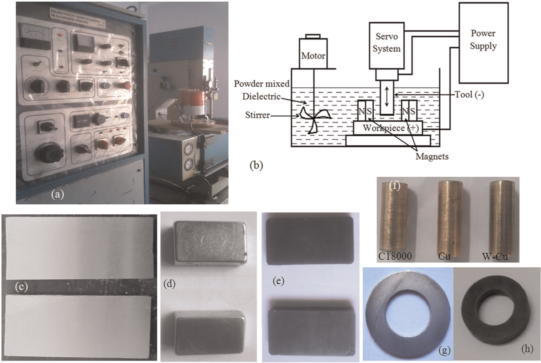
Experimental setup, workpiece, tools and bar and ring magnets used for experimentation: (a) pictorial view of setup, (b) schematic diagram of the experimental arrangement, (c) ground workpiece, (d) neodymium bar magnets (0.36 T), (e) ferrite bar magnets (0.1 T), (f) tools used for the study, (g) neodymium ring magnets (0.17 T) and (h) ferrite ring magnets (0.075 T).
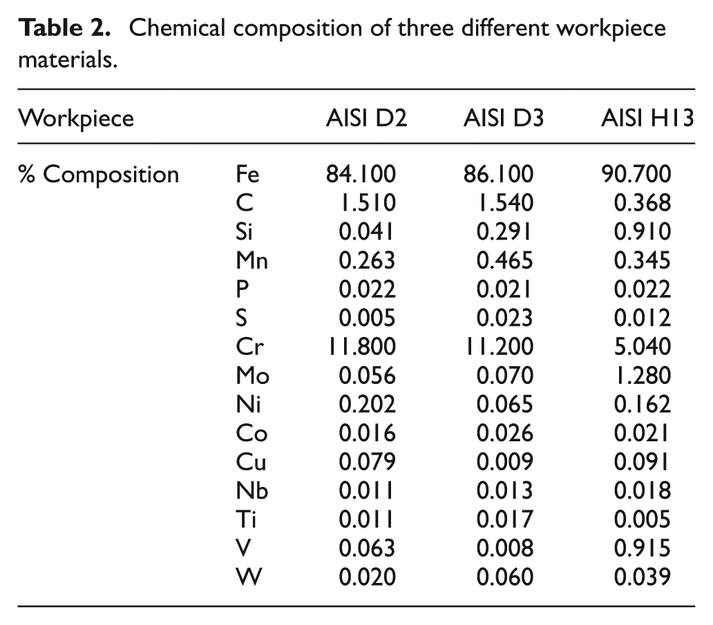
The chemical composition of workpieces was measured using Spectrometer Foundry Master (Oxford Instruments, UK) and is given in Table 2. Each workpiece was cut to a size of 100 × 50 × 10 mm3 for experiments (Figure 1(c)) and machined with 10-mm-diameter electrode (Figure 1(f)). Each workpiece was ground before the experimentation to maintain parallelism between the surfaces and the tool face. Two bar magnets facing opposite poles were placed at a distance of 20 mm from the workpiece in the machining area. Ring magnets with internal diameter of 20 mm were placed in such a way that the parts were machined at the center of the opening. Bar and ring magnets of different strengths used for this study are shown in Figure 1(d), (e), (g) and (h), respectively.
Chemical composition of three different workpiece materials.
Microstructure analysis was carried out using SEM machine (Model-LEO 435 VP; SEMTech Solutions, North Billerica, MA, USA) to study change in microstructure after EDM. Sample preparation was done as per standard requirement including cleaning before observations. XRD analyses of the machined samples were completed to verify the presence of elements on the surfaces using XRD testing machine (D8 ADVANCE; make: Bruker Corporation, Billerica, MA, USA). XRD tests were carried out at a scan rate of 5°/min for a 2θ range varying from 5° to 120°.
Results and discussion
The workpiece samples were analyzed before machining using SEM at suitable magnification. Figure 2(a)–(c) shows the SEM images of the three workpieces AISI D2, AISI D3 and AISI H13, respectively. SEM images of the ground samples showed the abrasive grains marks in the direction of lay. Some random scratch marks were visible for the AISI D2 workpiece (Figure 2(a)), which were caused during cutting of plates. Although most of these marks were removed by grinding, small traces were left. Some of the ploughed material during grinding was also seen, but no significant surface cracks were observed on the ground surface. These workpieces were machined at different process conditions using EDM/PMEDM, and their surface characterization through SEM micrograph study is discussed below.
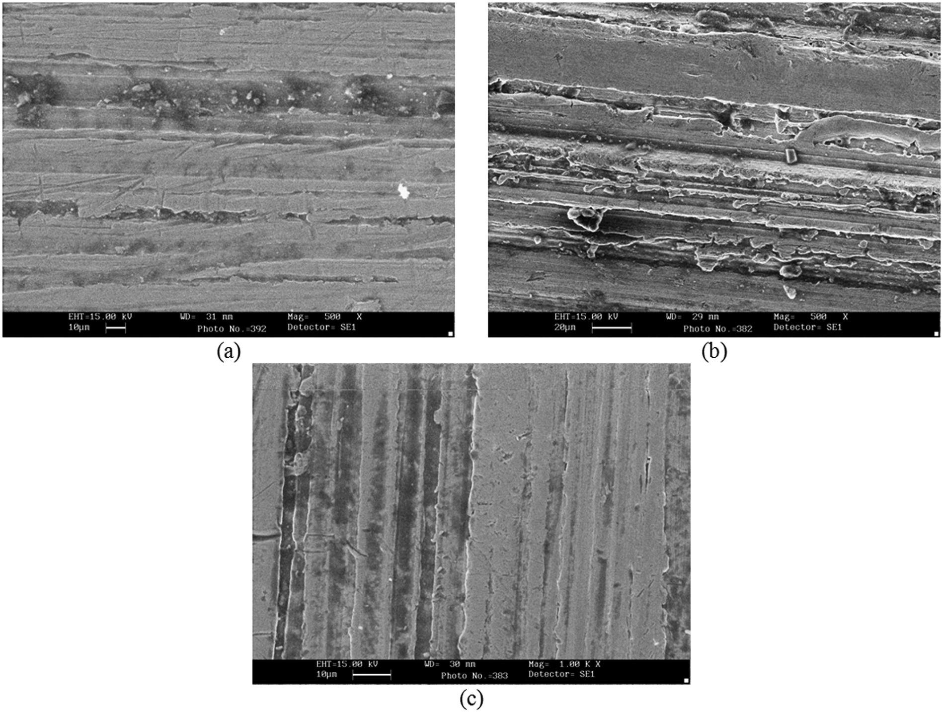
SEM images of the precision ground workpiece material: (a) AISI D2, (b) AISI D3 and (c) AISI H13 before machining.
AISI D2 workpiece
Figure 3(a) shows SEM micrograph for AISI D2 workpiece machined at 5 A current and 50 µs pulse-on time with tungsten powder (concentration 3 g/L) using copper tool without any magnetic field. As current is low, corresponding energy available is also low and less surface cracks were observed. Few multilayer deposition due to less frequency was observed at low powder concentration, and high SR was observed (R a = 6.3 µm). Some deposited particles were observed which migrated from tool and suspended powder. XRD plot confirmed traces of tungsten carbide (WC1-x and W2C) on the machined surface. With increase in tungsten carbide formation, the hardness of machined surface increases. Synthetic cohenite (Fe3C) formation was also observed on the surface. The hardness increased as cohenite was brittle and hard. At low current, lesser material addition took place and an increase in the microhardness was observed (193.4 HVN as compared to 86 HVN of parent metal). During spectroscopic analysis, an increase in carbon from 1.51% to 3.81% and tungsten from 0.02% to 0.215% was measured. This shows the migration of the material from suspended powders and dielectric.
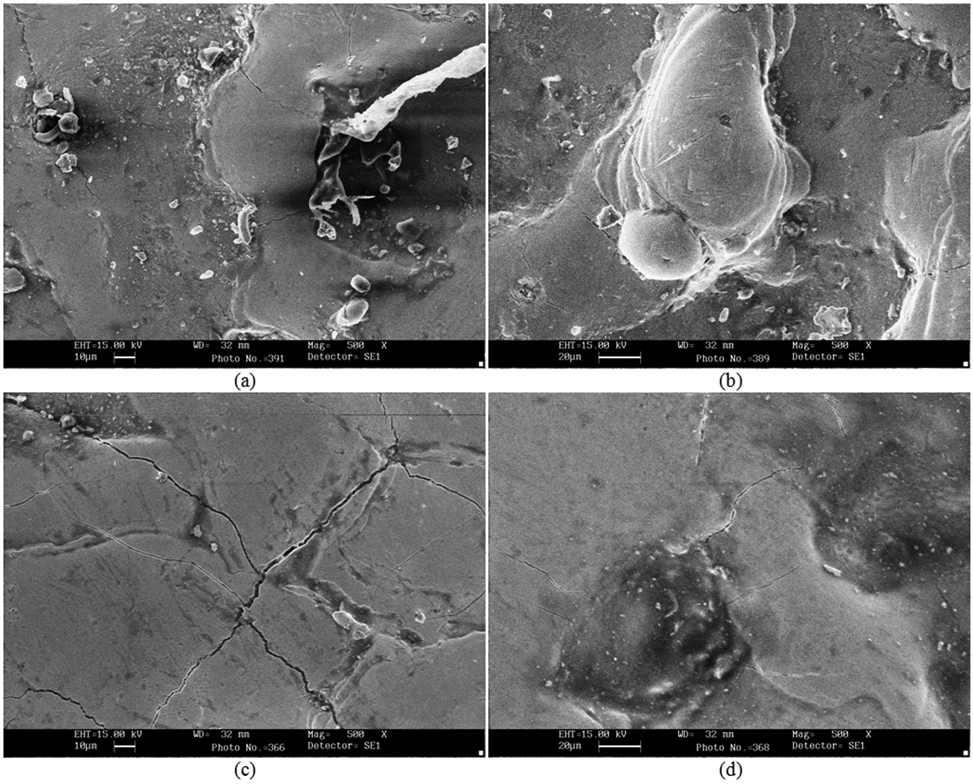
SEM images of machined AISI D2 workpiece under different process conditions: (a) AISI D2—W powder at concentration 3 g/L, Cu tool, current 5 A, pulse-on time 50 µs, no magnet; (b) AISI D2—W powder at concentration 6 g/L, C18000 tool, current 5 A, pulse-on time 20 µs, 0.36 T bar magnet; (c) AISI D2—no powder, W-Cu tool, current 7 A, pulse-on time 200 µs, 0.36 T bar magnet and (d) AISI D2—no powder, C18000 tool, current 8 A, pulse-on time 50 µs, 0.1 T bar magnet.
SEM micrograph of surface machined with tungsten powder (concentration 6 g/L), 5 A current, 20 µs pulse-on time and C18000 tool using bar magnets (0.36 T) is shown in Figure 3(b). Higher spark frequency was observed as powder concentration is more, and more resolidification deposition is observed. Due to this, more overlapped deposition observed causing a large difference between deposited peak and valley (deep groove) that resulted in higher roughness (R a = 7.3 µm). The machined surface was found rich in tungsten in the form of tungsten carbides (W2C and WC1-x) and carbon in the form of synthetic cohenite (Fe3C) with increase in the microhardness to 249.8 HVN. As moderate current and higher powder concentration were used, more tungsten and carbon migrated to the machined surface. Carbon content increased from 1.51% to 4.4%, and tungsten increased from 0.02% to 0.255% in the machined surface as seen in the spectroscopy analysis. Due to the presence of external magnetic field, C18000 (contains largely copper which is diamagnetic) produced an induced opposing magnetic field that caused repelling effect. Thus, in such cases, less migration of material from electrode is expected and tool wear is also expected to be less; however, MRR increased. Also, the XRD pattern (refer Figure 6(a)) shows some regions with wider peaks which is indicative of an amorphous structure possibly due to very rapid cooling in the range of ∼105–106 K/s. 27 The amorphous structure is generally accompanied with high hardness and brittleness.
SEM micrograph for AISI D2 workpiece machined with tungsten–copper tool and bar magnets of strength 0.36 T at 7 A current and 200 µs pulse-on time is shown in Figure 3(c). It can be observed from this figure that due to high current, more surface cracks are present. As powder was not used, low frequency of sparks results in avoiding multilayer deposition, and SR was measured to be 7.59 µm. The plasma impulse force was high leading to splashed out metal droplets (resolidified metal). Figure 3(d) shows SEM micrograph of surface machined with C18000 tool and bar magnets with strength 0.1 T at 8 A current and 50 µs pulse-on time. It can be observed that surface appearance was quite rough (measured R a = 10.18 µm). Impulse force was high giving resolidified splashed out metal. Moderate cracks were observed even at very high current value.
AISI D3 workpiece
Figure 4(a) shows micrograph of AISI D3 workpiece machined with titanium powder at a concentration of 3 g/L using C18000 tool with 0.075 T ring magnet at 5 A current and 20 µs pulse-on time. A more uniform spark was visible all over the surface leading to high MRR of 14.41 mm3/min. High frequency of spark was observed leading to deposited multilayer because of mixed powder. As moderate current was used, fewer cracks were observed on the machined surface. Figure 4(b) shows microstructure of AISI D3 workpiece machined with titanium powder at a concentration of 9 g/L with copper tool, 0.17 T ring magnet at 5 A current and 50 µs pulse-on time. Migrated deposited particles from tool or powder were observed. Moderate surface cracks were observed as the workpiece was machined at moderate current setting. Uniform spark was observed with some overlapped metal layers leading to a moderate SR (R a = 6.755 µm). XRD analysis (see Figure 6(b)) revealed the presence of cohenite synthetic, copper synthetic and titanium carbide on the machined surface. Titanium carbide formation enhances hardness and wear resistance, and hence, titanium carbide along with cohenite imparted very good hardness (248.8 HVN compared to 95 HVN of the parent material). The presence of copper on machined samples was apparently due to material migration from electrode. The results of spectrometry analysis showed that carbon increased from 1.54% to 3.46%, copper from 0.009% to 0.139% and titanium from 0.0172% to 0.022%. Diamagnetic property of copper (tool) and higher magnetic strength of ring magnet caused more repelling leading to marginal increase in copper content.
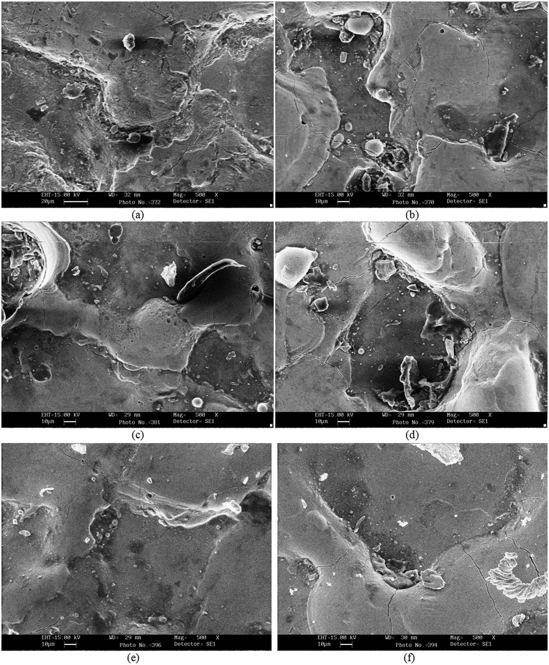
SEM images of machined AISI D3 workpiece under different process conditions: (a) AISI D3—Ti powder at concentration 3 g/L, C18000 tool, current 5 A, pulse-on time 20 µs, 0.075 T ring magnet; (b) AISI D3—Ti powder at concentration 9 g/L, Cu tool, current 5 A, pulse-on time 50 µs, 0.17 T ring magnet; (c) AISI D3—graphite powder at concentration 3 g/L, C18000 tool, current 7 A, pulse-on time 50 µs, 0.075 T ring magnet; (d) AISI D3—graphite powder at concentration 6 g/L, W-Cu tool, current 7 A, pulse-on time 20 µs, no magnet; (e) AISI D3—no powder, W-Cu tool, current 3 A, pulse-on time 100 µs, 0.1 T bar magnet and (f) AISI D3—no powder, Cu tool, current 8 A, pulse-on time 100 µs, 0.36 T bar magnet.
SEM of surface machined with graphite powder (3 g/L), 7 A current, 50 µs pulse-on time using C18000 tool and 0.075 T ring magnet is shown in Figure 4(c). Deposited multilayer was observed as a result of high spark frequency leading to high material removal (16.008 mm3/min) and SR (R a = 7.98 µm). Migrated deposited particles from tool electrode or powder were noticed at some points. As graphite powder is used, cracks were low even at high current because graphite absorbs total heat available. Carbon content increased with formation of austenite (CFe15.1) and cementite (Fe3C) and increased the microhardness (216.27 HVN). Trace of copper was also observed on the surface due to material transfer from tool. The carbon content increased from 1.54% to 3.6%.
Figure 4(d) shows the microstructure of surface machined with 7 A current, 20 µs pulse-on time, tungsten–copper tool and graphite powder (6 g/L) without any magnetic field. From the microstructure, it was observed that even though the current is quite high, surface cracks were negligible due to low pulse-on duration. More peaks and valleys were observed representing more craters leading to a high material removal (19.87 mm3/min). Peaks and valleys formed appear shallow in nature, with smooth multilayer leading to low SR (R a = 5.81 µm). XRD results showed the presence of cohenite synthetic (Fe3C) and tungsten carbide (WC1-x) on the surface. Due to high current, more carbon (from dielectric and powder) forming carbide with the migrated tungsten (from electrode) was observed. The surface microhardness increased to 233.24 HVN. Spectrometry analysis showed increase in carbon from 1.54% to 4.46% and tungsten from 0.0606% to 1.78%.
Figure 4(e) shows micrograph of workpiece machined with tungsten–copper tool with 0.09 T bar magnets at 3 A current and 100 µs pulse-on time. As current is very low, very low energy was available, hence surface cracks were minute and material removal is low (2.926 mm3/min). Randomly distributed shallow peaks and valleys were observed. SEM micrograph for AISI D3 workpiece machined with copper tool with 0.36 T bar magnets at 8 A current and 100 µs pulse-on time is shown in Figure 4(f). As deposited multilayer is absent, it implies lesser spark frequency due to no powder addition. But deep and wider craters were observed leading to high material removal (11.57 mm3/min) and high roughness (R a = 9.71 µm). The XRD plots shown in Figure 6(c) indicated the presence of additional carbon in the form of cementite (from dielectric) and copper synthetic (from tool) on the machined surface. High current for machining was responsible for higher carbon after dissociation of dielectric. Cementite was the main source for increased hardness (272.33 HVN) on the machined sample with copper acting as a supporting element for increasing strength.
AISI H13 workpiece
Figure 5(a) shows the SEM image of surface machined with titanium powder (6 g/L), copper tool, 3 A current, 20 µs pulse-on time and 0.1 T bar magnets. Uniformly deposited multilayer was present throughout the machined surface due to high spark frequency caused by higher powder concentration. The material removal was low (6.297 mm 3 /min) due to less energy with low current and pulse-on time. No cracks were observed on the surface even at 500× magnification. Titanium in carbide form (TiC), copper synthetic and cohenite synthetic (Fe3C) were observed on the machined surface during XRD. A moderate hardness value (164.529 HVN) was observed as compared to 75.318 HVN measured in the parent material. Spectrometry analysis revealed that carbon increased from 0.368% to 2.04%, copper 0.0909% to 0.493% and titanium 0.0055% to 0.0125%, indicating material migration from powder, dielectric and tool. Figure 5(b) shows the SEM image of the workpiece machined with tungsten–copper tool, 3 A current, 50 µs pulse-on time, titanium powder (3 g/L) and 0.36 T bar magnets. Microstructure showed resolidified metal particles showing higher impulse force. Some migrated particles from tool or used powder were seen. XRD result (represented in Figure 6(d)) showed formation of iron–tungsten carbide (Fe6W6C) with cohenite synthetic (Fe3C) and some traces of titanium carbide (TiC). Spectrometry analysis showed that carbon increased from 0.368% to 1.98% and titanium increased from 0.0055% to 0.0079%. No significant change in tungsten or copper was observed due to the repelling effect of the copper–tungsten tool material under the application of the highest strength magnetic field (0.36 T).
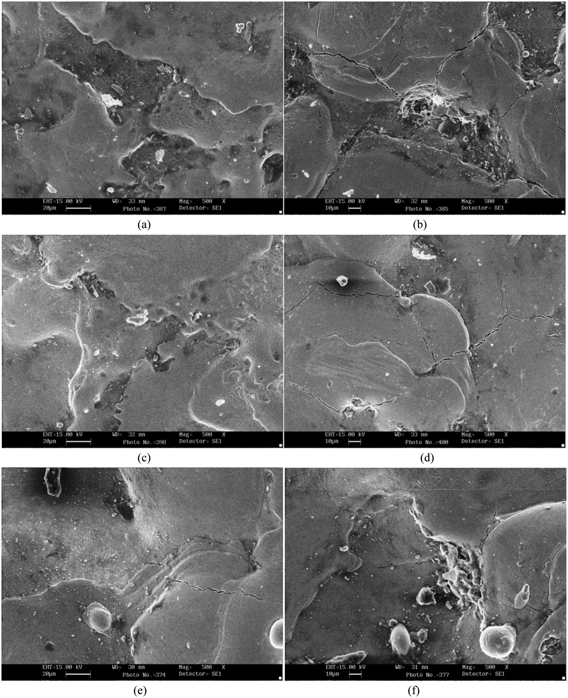
SEM images of machined AISI H13 workpiece under different process conditions: (a) AISI H13—Ti powder at concentration 6 g/L, Cu tool, current 3 A, pulse-on time 20 µs, 0.1 T bar magnet; (b) AISI H13—Ti powder at concentration 3 g/L, W-Cu tool, current 3 A, pulse-on time 50 µs, 0.36 T bar magnet; (c) AISI H13—Ti powder at concentration 6 g/L, Cu tool, current 3 A, pulse-on time 20 µs, 0.075 T ring magnet; (d) AISI H13—W powder at concentration 6 g/L, Cu tool, current 7 A, pulse-on time 100 µs, 0.075 T ring magnet; (e) AISI H13—no powder, C18000 tool, current 6 A, pulse-on time 100 µs, no magnet and (f) AISI H13—no powder, W-Cu tool, current 8 A, pulse-on time 200 µs, no magnet.
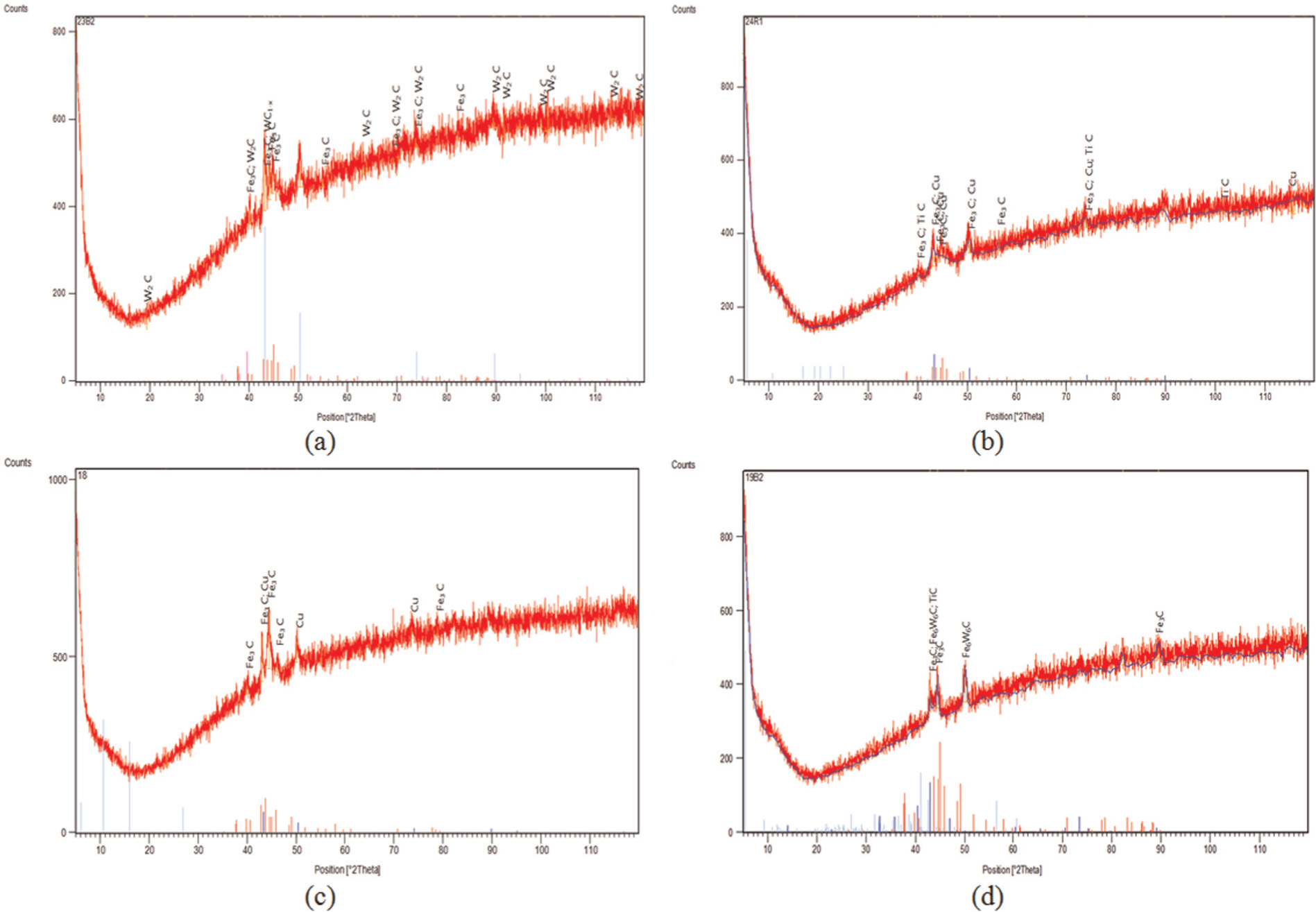
XRD plots: (a) AISI D2—W powder at concentration 6 g/L, C18000 tool, current 5 A, pulse-on time 20 µs, 0.36 T bar magnet; (b) AISI D3—Ti powder at concentration 9 g/L, Cu tool, current 5 A, pulse-on time 50 µs, 0.17 T ring magnet; (c) AISI D3—no powder, Cu tool, current 8 A, pulse-on time 100 µs, 0.36 T bar magnet and (d) AISI H13—Ti powder at concentration 3 g/L, W-Cu tool, current 3 A, pulse-on time 50 µs, 0.36 T bar magnet.
Figure 5(c) shows the SEM image of the workpiece machined with titanium powder (6 g/L), copper tool, 3 A current, 20 µs pulse-on time and 0.075 T ring magnet. As current is very low, no surface cracks were observed on the surface. SEM micrograph for surface machined with copper tool, tungsten powder (6 g/L), 0.075 T ring magnet, 7 A current and 100 µs pulse-on time is shown in Figure 5(d). Deposition from tool and/or powder was observed. Deposited multilayer (due to more spark frequency) was observed with thick deposited layer creating a wide gap between peak and valley leading to increased roughness (R a = 8.7125 µm). As current was very high, more cracks were observed on the surface (clearly visible at 500× magnification). Uniform spark was observed over the entire surface leading to high material removal (13.055 mm 3 /min).
SEM image of machined surface using C18000 tool, 6 A current and 100 µs pulse-on time with no magnetic field and powder is shown in Figure 5(e). Some migrated particles were seen deposited on the surface from tool. Smooth multilayer deposition was noticed at 500× magnification. Higher impact force and resolidified metal were noticed. Similarly, SEM image of machined surface using tungsten–copper tool, 8 A current and 200 µs pulse-on time with no powder and magnetic field is represented in Figure 5(f). Resolidified metal droplets as a result of high impact force were observed on the surface. Several peaks and valleys were observed which lead to high roughness (R a = 8.37 µm). Migration of elements was observed from the tungsten–copper tool as no powder was used in this case. More cracks were observed as machining was carried out at higher current and pulse-on value. From XRD analysis, it was observed that cohenite synthetic (Fe3C), tungsten carbide (WC1-x) and copper synthetic are formed on the machined surface. Even though the base material was not so hard, the hardness of the machined sample (213.63 HVN) after machining was higher due to the presence of tungsten carbide and copper particles. As current is high and no repelling force existed in absence of external magnetic field, more material migration from the tool and the dielectric was observed.
Tables 3 –5 provide summaries of all the findings and observations for AISI D2, AISI D3 and AISI H13, respectively.
Summary of microscopic observations for AISI D2 material.
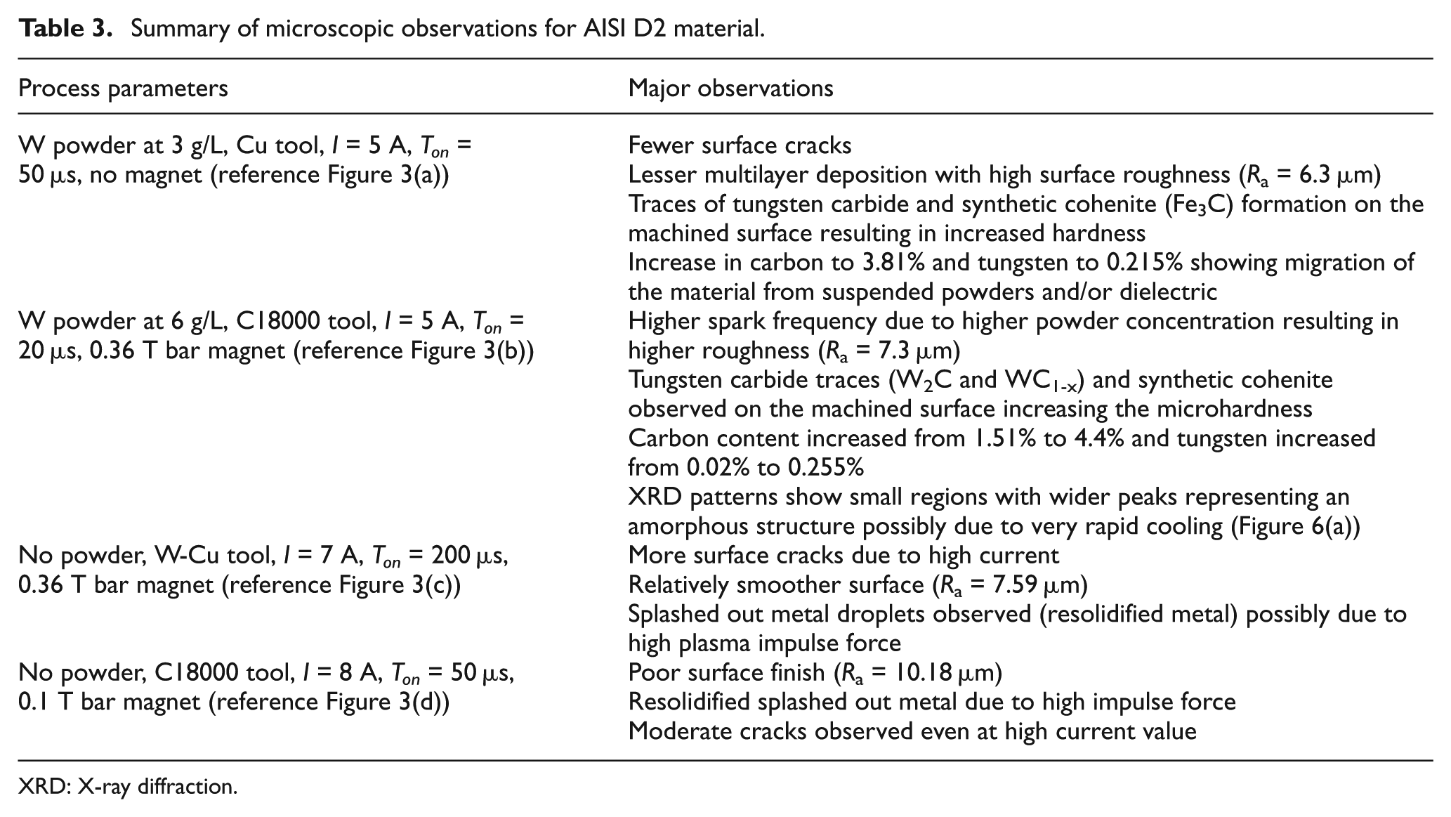
XRD: X-ray diffraction.
Summary of microscopic observations for AISI D3 material.
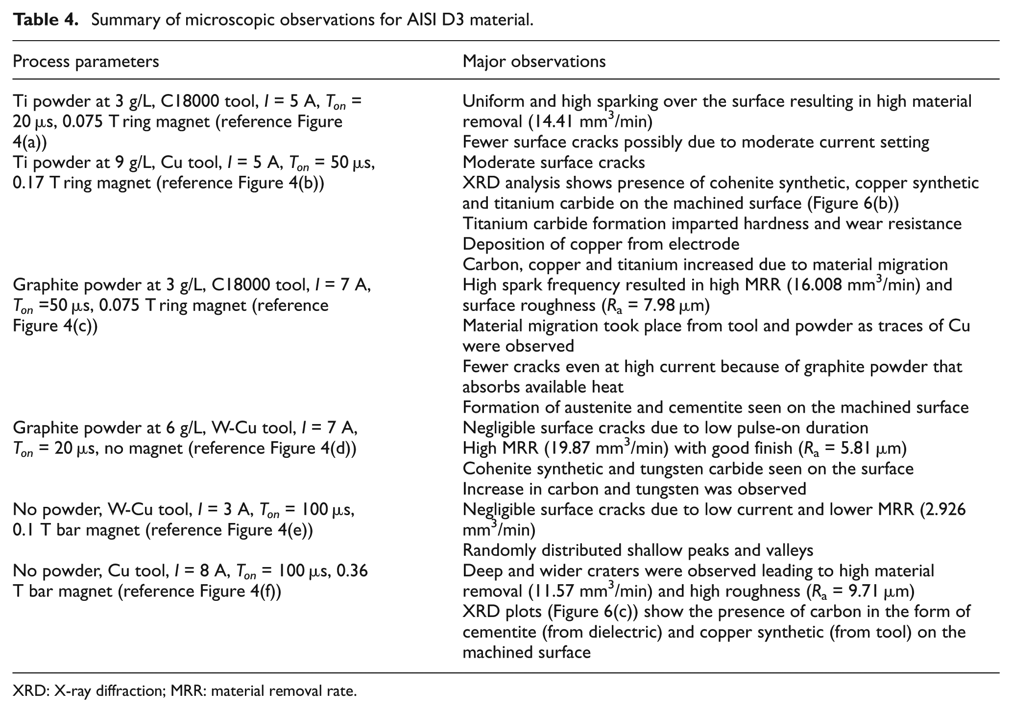
XRD: X-ray diffraction; MRR: material removal rate.
Summary of microscopic observations for AISI H13 material.
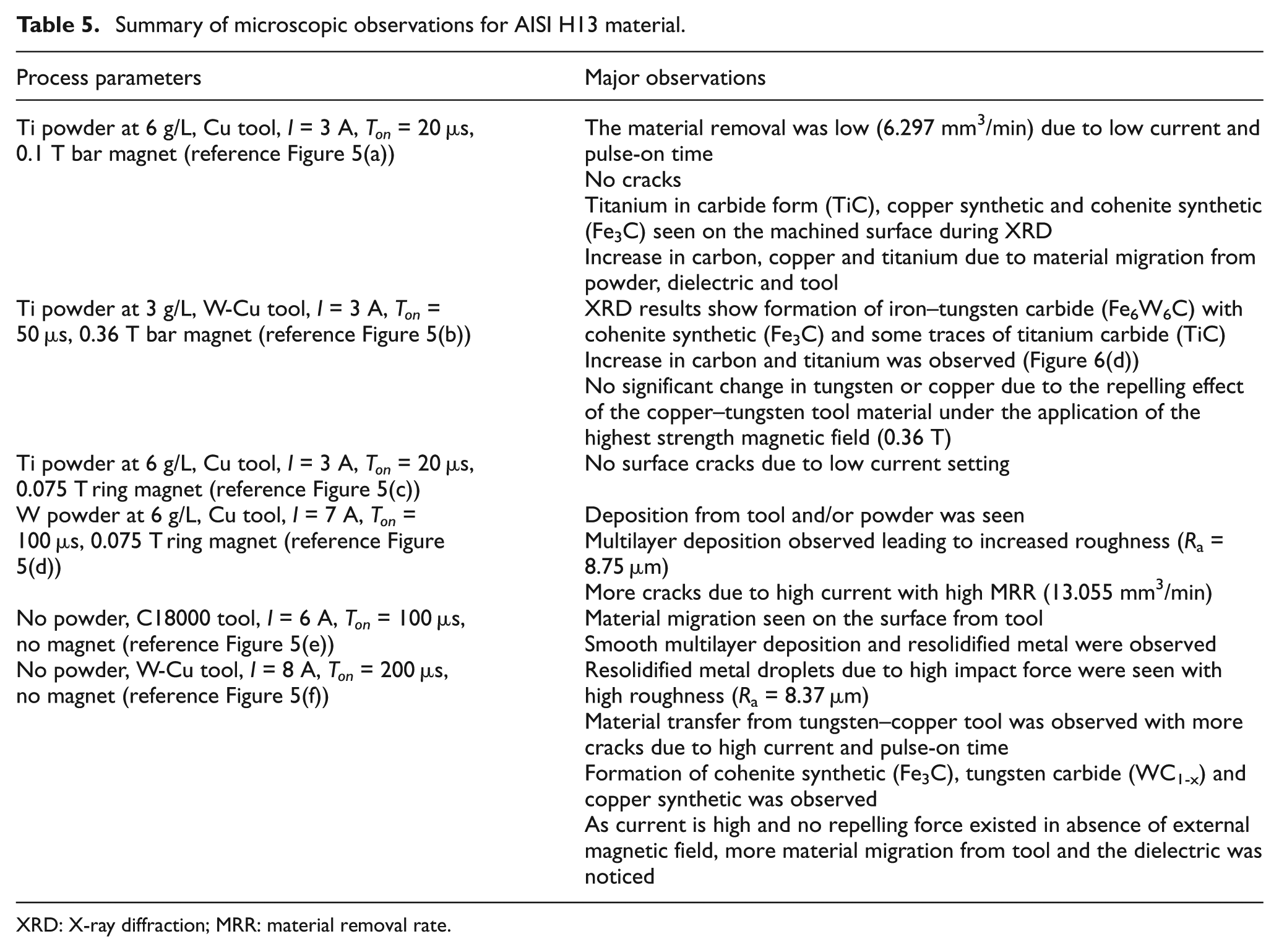
XRD: X-ray diffraction; MRR: material removal rate.
Analysis for MRR and SR using PMEDM with associated magnetic field
The three die steel materials were also analyzed for MRR and SR after the completion of the machining process using the ring magnet. The signal-to-noise ratio for both MRR and SR was computed for detailed analysis considering MRR as higher the better response and SR as lower the best response type. Analysis of variance was computed to identify the significant factors and their impact on both the responses. Figures 7 and 8 provide an insight into the effect of each factor on MRR and SR, respectively. As can be seen from the plot, current is the most significant factor, and a higher MRR can be realized at high current setting. Magnetic field strength has marginal impact in varying the MRR, and higher MRR could be seen with high magnetic field strength. As can be seen in Figure 8 for SR, an expected deterioration of finish was observed with increase in current. Furthermore, a superior finish can be realized using magnetic field of lower strength because higher magnetic field pulling of material from crater creates deeper crater resulting in poor finish.
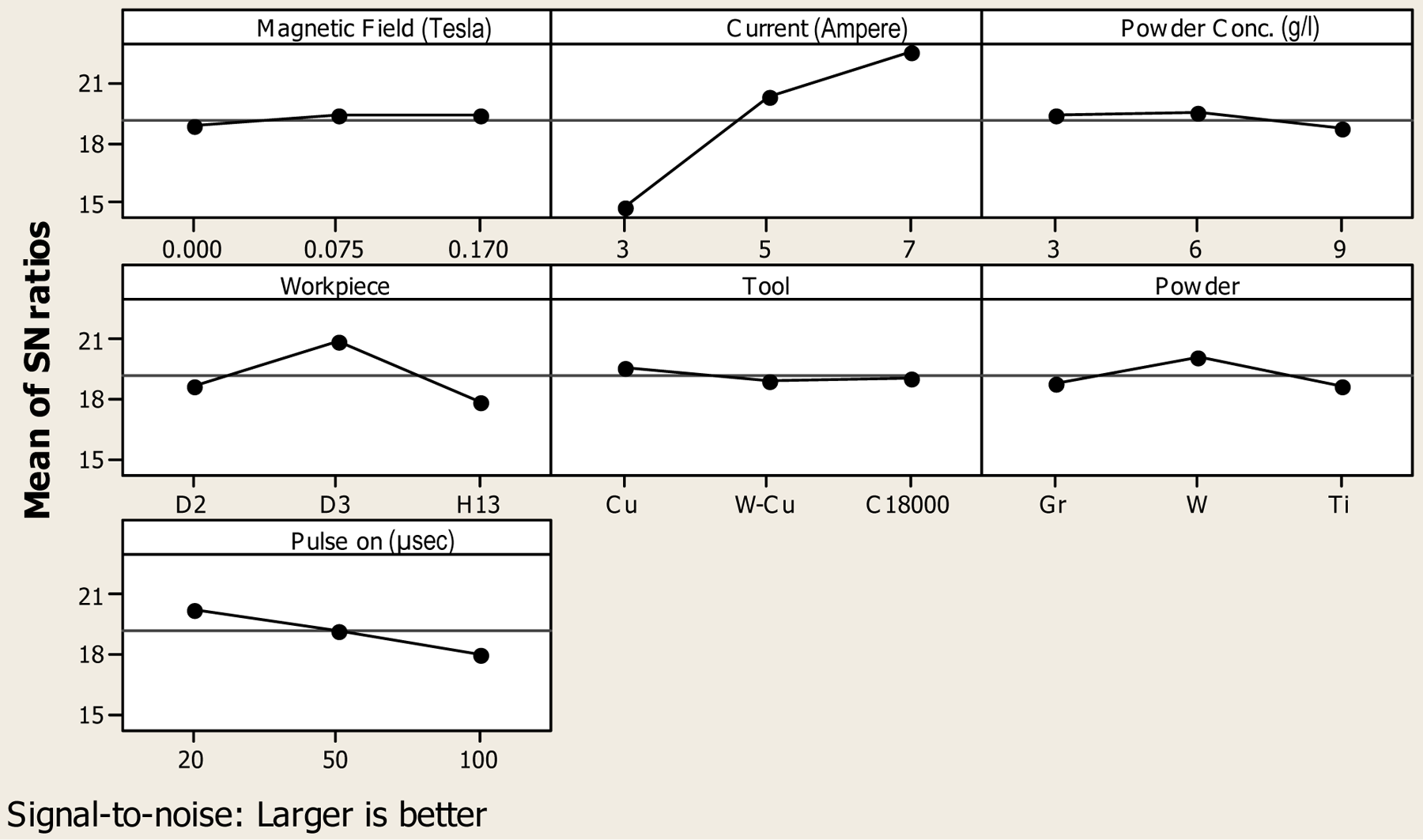
Analysis of factor significance on material removal during magnetic field–assisted PMEDM.
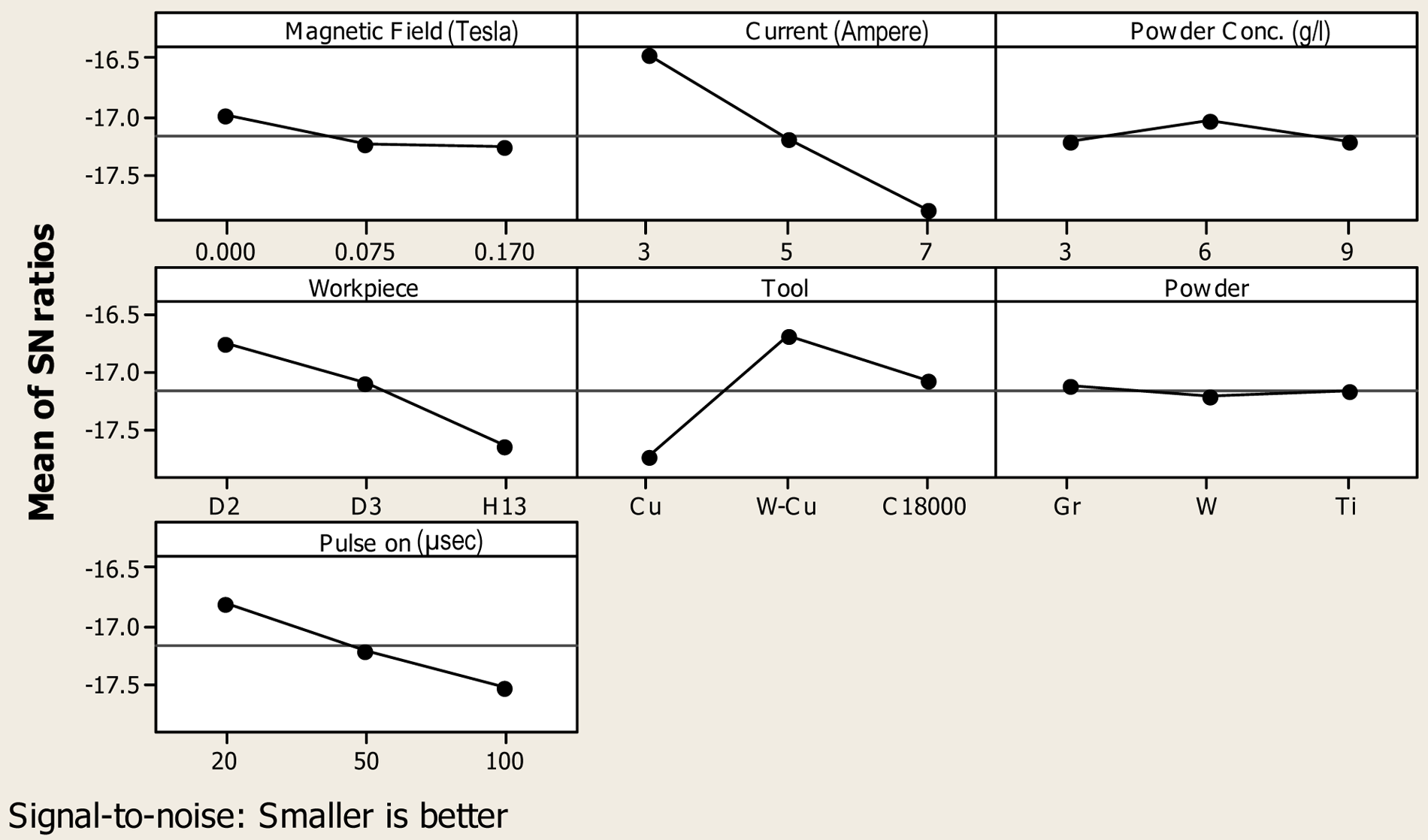
Analysis of factor significance on surface finish during magnetic field–assisted PMEDM.
Conclusion
During this study, the effect of several process parameters was assessed while machining the three most commonly used die steels for surface modification using magnetic field–assisted EDM/PMEDM process. Surface characterization was done using the SEM micrographs of samples and was then correlated with the microhardness and SR. More than 200% increase in the microhardness was observed after machining. Microstructure and subsequent XRD analysis confirmed material migration majorly from suspended powder, dielectric and electrode. Use of external magnetic field helped to improve the material removal from workpiece. The shape of the magnet (bar or ring) does not have any effect on process performance, but increased strength of magnetic field resulted in better expelling of material from workpiece. External magnetic field also restricted the material migration from electrode (especially in copper-based diamagnetic material), thus reducing the TWR. Under favorable process conditions, tungsten and titanium carbide formation was observed thereby increasing the microhardness significantly. XRD analysis also showed amorphous structure due to rapid cooling. Titanium, tungsten and graphite powder aided favorably the increase in the microhardness in AISI D2, D3 and H13 graded die steels, and almost 200% increase in carbon was quantified on the machined surface.
Footnotes
Declaration of conflicting interests
The authors declare that there is no conflict of interest.
Funding
This research received financial support from University Grants Commission, New Delhi, India.