
Abstract
Universal machine tool settings with higher-order motion coefficients are developed to make accurate modification considering the actual machine geometric error compensation for spiral bevel and hypoid gears. First, the universal machine tool settings are exploited for the identification of the real tooth flank form error. Furthermore, the error sensitivity analysis method and an improved Levenberg–Marquardt algorithm with a trust-region strategy are utilized to obtain the solution of modification amount. Finally, a higher-order modification methodology for the universal machine tool settings is proposed which mainly covers three vital parts: (a) optimized selection of the modification settings, (b) modification of universal machine tool settings, and (c) machine geometric error compensation. Especially, a higher-accuracy fitting method for the form error tooth flank is investigated. Some numerical examples verify that the tooth flank form error after higher-order modification can reach less than 0.5 µm or even a smaller one, and the position error after compensating process spindle can be reduced from 0.0044861° to 0.0009232°. In addition, given experimental result can validate the feasibility of the proposed methodology.
Keywords
Introduction
The sophisticated flank optimizations have increasingly been an essential stage in design for spiral bevel and hypoid gears because of continually demanding more strength and less noise. In the actual process, the tooth flank form geometry of spiral bevel and hypoid gears may deviate from the target tooth surface. Variation of cutting forces, heat treatment deformation, and some other unpredictable factors may cause noisy operation and premature failure from the edge contact and highly concentrated stresses.1,2 Consequently, the modification technique is usually employed in advance to make the sophisticated flank optimizations with modified machine tool settings and tooth flank form errors. In the past few decades, while there are numerous modifications based on various kinds of machine tools such as Gleason or Klingelnberg series, some problems about low efficiency and poor accuracy still existed due to plenty of setting categories, complex generation motions, and redundancy of machine tool settings.
More recently, machine settings modification has been developed into an active research area, where it is of necessity to consider the sensitivity matrix and tooth form flank topographic deviations from the coordinate-measuring machine (CMM) or the gear-measuring center.3,4 This process usually proceeds as follows: (a) the modification model is established to obtain a real tooth form with universal machine settings; (b) modified machine settings are determined with a constructed sensitivity matrix and the measured deviation on the CMM; (c) modification variation is calculated to minimize real surface deviations till the requirements are satisfied.
With state-of-the-art computer numerical control (CNC) technology, the machine settings modification technology has been being continually developed. First, with universal motion concept (UMC) dramatically enhanced and developed by Stadtfeld and Gaiser, 5 research on universal machine tool settings has become an increasingly hot topic because of more freedoms provided for generating tooth surfaces with modified complex geometries 6 and more flexible application of face-milling and face-hobbing processes. Consequently, some advanced algorithms about gear design and manufacturing have been developed and implemented. Astoul et al. 7 formulated a mathematical model utilizing universal machine settings to provide a foundation for gear tooth contact analysis (TCA) and rendered a simple and robust method to simulate the generating and meshing processes. Fan 8 obtained a universal generation model (UGM) by applying the basic machine tool settings represented by a series of higher-order polynomials to calculate tooth surface coordinates for any type of processes based on a free-form CNC hypoid generator. 9 Second, the ease-off tooth flank modification of machine settings is gaining more popularity. Artoni and colleagues10,11 proposed some optimizations for the ease-off flank modification by means of the actual machine tool settings to achieve high performance in terms of more strength, less noise, and other requirements. Shih and Chen12,13 carried out a novel ease-off flank modification with the Cartesian-type CNC hypoid generator, after simulating all primary processes for spiral bevel and hypoid gears. Simon14,15 provided an optimized tooth surface geometry to execute generating motion on the cradle-type machine tool. Then, he presented some optimizations about machine settings for significant reductions in maximum tooth contact pressure and transmission error as well as for other superior properties. Finally, distinguished from the conventional first- or second-order tooth correction, the higher-order modification has been proposed. Fan et al. 16 described a new approach for the face-milled spiral bevel and hypoid gears. The higher-order components of the error surfaces may be corrected using the higher-order universal motions. The corrective universal motion coefficients are determined through an optimization process with the target of minimizing the tooth flank form error. Wang and Fong 17 presented fourth-order motion curves to get access to a modified radial motion (MRM) correction in the machine plane of a CNC hypoid generator with an arbitrary predetermined contact path on the pinion tooth surface.
In this article, a new modification methodology of universal machine tool settings is proposed to obtain more accurate tooth flank form error modification and machine geometric error compensation of spiral bevel and hypoid gears, based on the synthesis and analysis of aforementioned researches. It is worth noting that an error sensitivity analysis method is applied to select the optimal machine settings, and a Levenberg–Marquardt (L-M) algorithm with a trust-region strategy is utilized to obtain the stable solutions. Furthermore, a higher-precision fitting method for form error tooth flank and a good compensation for machine geometric errors are investigated to improve manufacturing accuracy. In section “Universal machine tool settings,” a mathematical model of the tooth flank is established with the application of universal machine settings. The detailed modification approach of universal machine tool settings is presented in section “Modification of universal machine tool settings,” and experimental result is provided to validate the feasibility of the proposed methodology in section “Experimental result and discussion.” Finally, conclusions are given in section “Conclusion.”
Universal machine tool settings
While so many types of methods have been employed to process spiral bevel and hypoid gears, these methods can be summarized into two major categories:
Face milling, which is the single indexing one applied for the tapered tooth with Gleason series machine tool by SGM/SFT/SGDH/HGM/HFT/HGDH. 18
Face hobbing, which is the continuous indexing process provided for the equal tooth with Klingelnberg’s and Oerlikon’s machine tool by TRI-AC® and PENTAC®. Simultaneously, Gleason Phoenix® II series CNC hypoid gear generator 19 can also execute the face hobbing.
Undisputedly, a large number of researchers have involved all kinds of the above processing approaches. However, most methods are in lack of generality since many undertaken descriptions and investigations for spiral bevel and hypoid gears are made just with a specific method. Due to growing CNC technology, an UGM by Gleason Works has been developed to be applicable to tooth flank geometric description and to simulation of precise simultaneous motions. 10 Although gear-processing machine tools can be divided into two main categories: mechanical style and CNC style, they can be in a unified transformation based on universal machine settings.
The UGM developed in this article consists of eight basic motion settings, in which all processing types are considered into precise implementation of real-time relative motion between the cutter and the gear blank. As represented in Figure 1, UGM can execute face milling with universal machine settings. These machine settings can be variable during generation as a series of higher-order polynomial functions of the cradle rotation angle q as follows

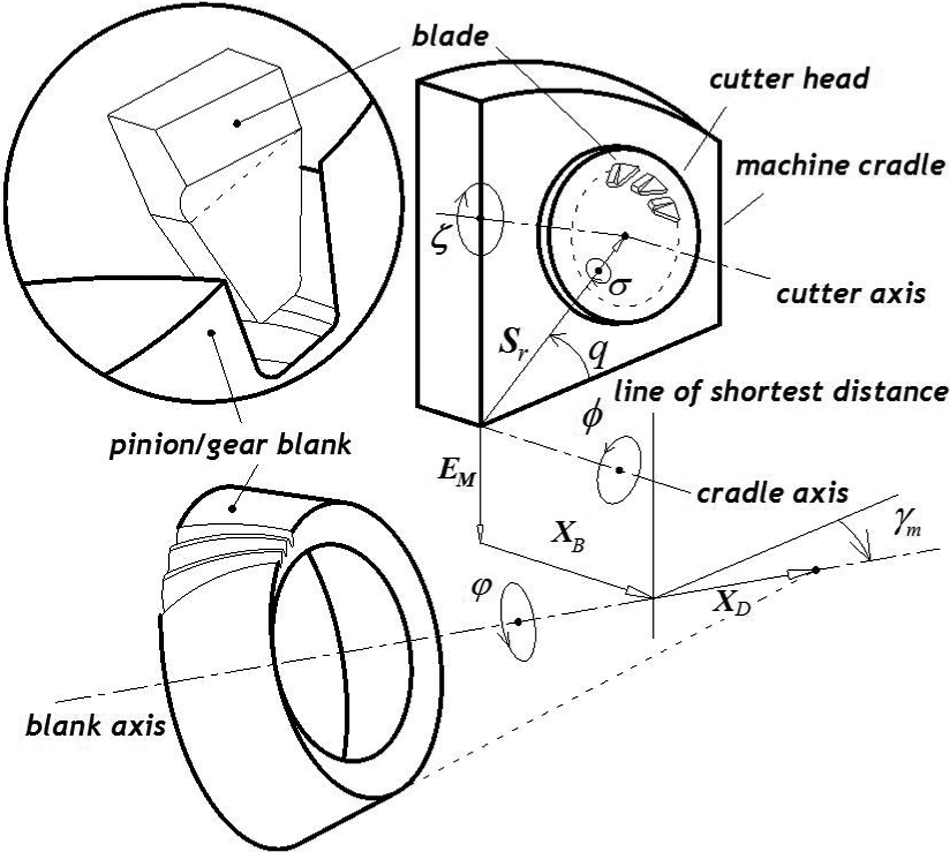
UGM based on universal machine tool settings.
where these coefficients about the machine settings are so-called universal motion coefficients.5,9
Each machine setting is analytically described as a motion element associated with the relative coordinate system. After the main coordinate systems, rigidly fixed to the blank and the cutter head, are established, their motions are executed by calculating transformation matrices from the cutter to the blank. Therefore, the tooth flank equation can be obtained as follows

where µ and θ represent the flank coordinates. 18 To eliminate the variable t, the tooth flank equation can be expressed as

According to given blank data, after establishing some geometric relationships such as L, δp, and axis direction, each node point of the tooth flank can be calculated with a uniform discretization by the following formula

Modification of universal machine tool settings
Real tooth flank form error
Tooth flank form error, which actually stems from many aspects, mainly includes the cutter shape and position error as well as the spatial geometric error of each machine tool spindle. In the derivation of tooth flank equations, it can be demonstrated that the vector of a tooth flank point is the function on the machine tool settings. Tooth flank form error at each point can be considered into the projection from the differential incremental function along its normal vector direction to the point vector function.
19
Assuming tooth flank form errors stem from

While implementing the modification in actual process, the real tooth flank can be generally measured by CMM. 12 Several practices have proved that the comprehensive effects of various errors, under certain conditions, can be reflected by the working flank and form processing error due to its stability and repeatability. 20 In this sense, the error value through accurate measurement of the processed gear can indicate most of the comprehensive effects from all error sources. The measured tooth flank form coordinate data can be obtained and numerically represented as

Error sensitivity analysis and modification amount
Litvin et al. 21 proposed that any point error is the superposition of a series of small tooth flank errors. Its projection along the normal direction of the theoretical tooth flank is the normal error, which is a basic standard to express the tooth flank form error22,23 represented as

By substituting corresponding coordinate parameters of measured points on the theoretical tooth flank in their turn into equation (7),
Moreover, in order to indicate the response of tooth error to each machine tool setting, what needs to be done is to make analysis of the tooth error sensitivity. To this end, the variation of tooth error flank represented by grid points can be determined by the formula

Hence, with homogeneous coordinate transformation, the normal error of all tooth flank points on the measurement position is expressed as a matrix form
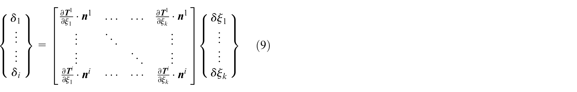
It can be simplified into

where
Higher-order modification methodology
In this article, a closed-loop process of universal machine tool settings modification is presented based on repeated measurements on a CMM for the flank form error after each modification. If it cannot meet the accuracy requirement, we need to make accurate modification of selected machine settings and their orders of universal motion coefficients. Figure 2 shows the basic universal machine tool settings modification. The automotive modification can be completed based on a network and software system, which includes a primary server, engineering workstations, machine tool, and metrology equipment. 16 Here, to simply describe the procedure, there are three important stages to undergo.

Flowchart of universal machine tool settings modification.
Optimized selection of the modification settings
In such modification, there is a strong nonlinearity as it involves too many machine tool settings as unknown modified variables. As a result, it can cause the coupling impact of one machine setting on the other settings and the ill-conditioning problem of established objective function. Thus, an optimized modification approach with the least machine settings is developed based on error sensitivity analysis.12,13 First, sensitivity coefficients of all universal machine settings, relative settings with the larger positive sensitive changes, are determined to make modification. Generally, the number of modified machine settings is no more than three. Then, with modification amount calculated by applying the relative algorithm, the determined machine settings are used to make modification. If the requirements cannot be met, the order of modified machine settings needs to be increased. Now, there are two accesses to verification of the results: conducting the actual process to measure the flank error and inputting the modification amount into the CMM to gain tooth error. Apparently, the latter method is optimal when it comes to production efficiency and cost.
As shown in Figure 3, nine tooth points remarked as
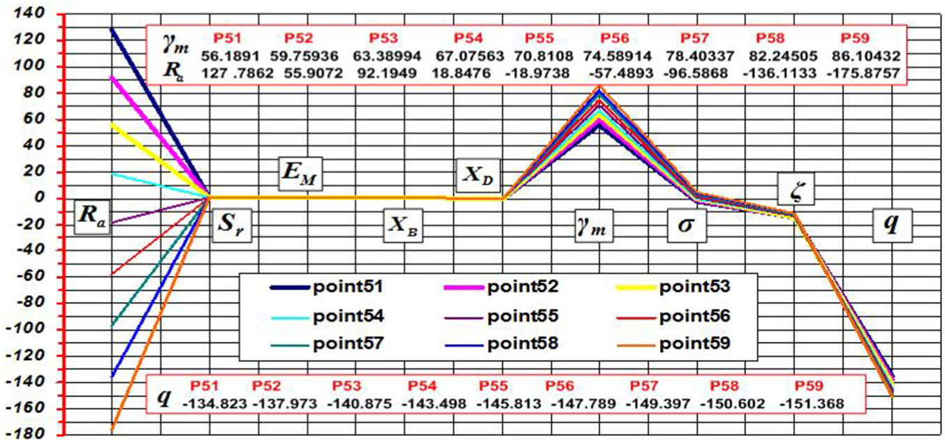
Sensitivity coefficients of first-order universal machine settings.
Modification of universal machine tool settings
Essentially, the modification of universal machine tool settings is a nonlinear minimization and optimization process of tooth flank error by the solution of equation (10). Here, it is an over-determined nonlinear equation set with ubiquitous ill-conditioning. Although there are some proposed methods including the three main categories: one-step method, iterative method, and iterative method with step control,
10
it is still hard to get a stable solution. Recently, considering the reliability and robustness of obtained solutions, the iterative technique with step control is commonly used to get the optimal solution. In this article, the L-M algorithm with a trust-region strategy is adopted, whose detailed description can be found in Gabiccini et al.
10
It is worth remarking that this algorithm has made some improvements. As equation (10) can be represented as

The improved µk is expressed as
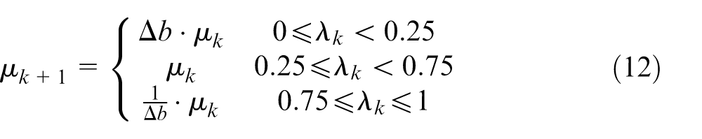
where the quadratic approximation
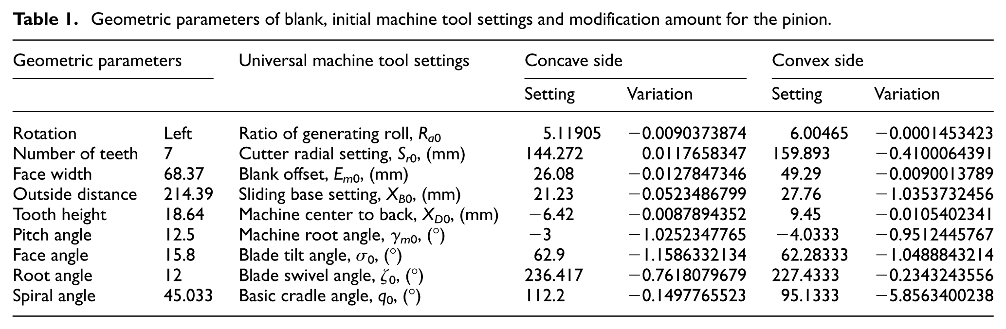
In this study, it can render the machine settings with different orders and their numerical results, respectively. In the modification, the Sigma7 CMM is adopted to measure the pinion tooth form error. First, the first-order machine tool settings are provided from the modification card for the pinion processed with face milling. As the modified universal machine tool settings are specific to a given production process, tooling, and other conditions where the tooth flank form errors are repeatable. 16 The basic geometric parameters and the first-order machine tool settings and their modification amount calculated by the aforementioned algorithms are shown in Table 1. It can be known that the relative universal machine tool settings q0, Ra0, and γm0 have more modification amount and they need to be selected as main modification target settings.
Geometric parameters of blank, initial machine tool settings and modification amount for the pinion.
Based on the selected universal machine settings with higher-order coefficients, the tooth flank with form error after accurate modification can be obtained with the L-M algorithm with a trust-region strategy. Previously, the tooth flank topography with form error is always represented into difference surface.8,16 Actually, it can be represented by the polynomial fitting method as follows

In the above fitting, the second or third orders of the variables x and y are generally selected. The c = [c0, c1, c2, …] can indicate specific geometric meanings. 16 And the order of universal machine settings is consistent with the order of the form error flank.
Distinguished from conventional polynomial fitting method, an interpolation fitting method is exploited. Here, the residual ease-off problem 3 that is always ignored in previous studies is taken into account. In addition, it gives goodness of fit including the sum of squared error (SSE), R-square (R-S), adjusted R-square (AR-S), and root mean-squared error (RMSE) to reduce the residual ease-off.
For the same original form error tooth flank with 5 × 9 datapoints before modification (see Figure 4), Table 2 is goodness comparison of two fitting methods for the tooth flank after the modification of the selected universal settings q, Ra, and γm with the second-order polynomial functions. Some relevant comparisons indicate that the interpolation method has better goodness of fit than the conventional method. Besides, among some interpolation techniques, the cubic interpolation is the optimal one, since it has the best goodness of fit and the best fitting boundary condition. Similarly, for previous polynomial fittings, the fitting with x = 3 and y = 3 is the optimal one, as this method with a higher order has better goodness of fit. However, the singular phenomenon of the tooth flank boundary will lead to poor smoothness when the order is more than 4. The form error flanks with two optimal fittings from different types of fitting methods are represented in Figure 5. Here, the tooth flank with the optimal polynomial fitting method can be represented by

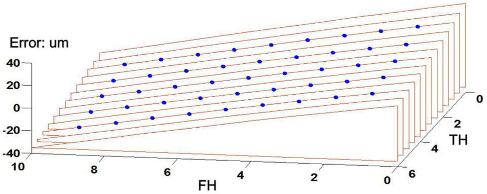
Original real tooth flank before modification.
Goodness comparison of two fitting methods.
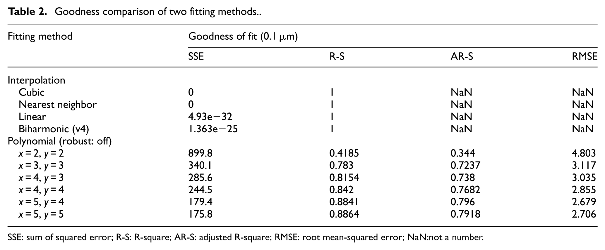
SSE: sum of squared error; R-S: R-square; AR-S: adjusted R-square; RMSE: root mean-squared error; NaN:not a number.
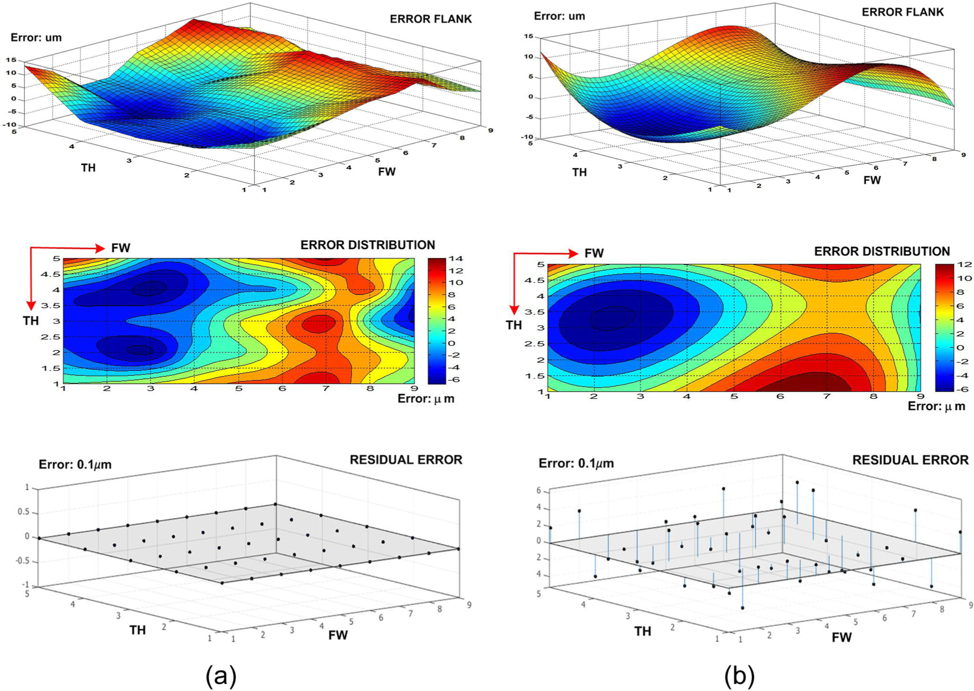
Form error flanks after the second-order machine settings modification with different fitting methods: (a) interpolation (cubic) and (b) polynomial (x = 3, y = 3).
It can be seen that the form error after the second-order machine settings modification has been significantly reduced. From a numerical point of view, the RMSE of the original tooth flank is 19.64 µm, the RMSE after applying the cubic interpolation method is 4.28 µm, and the RMSE after employing the polynomial fitting is 3.97 µm. Although the tooth form error value of cubic interpolation method is smaller and the smoothness is not better than the polynomial fitting, its validation of tooth accuracy is better, since the residual error of the former is 0, while the RMSE of the latter is 3. Especially, for the higher-order modification, the accuracy of the cubic interpolation method is higher, and there is no residual ease-off. Additionally, this article presents the error distribution after one modification, making the tooth flank more intuitive and more accurate than the case with conventional methods. In summary, cubic interpolation method is the most suitable to be applied for expression of the real tooth flank form error, because the fitting method is of higher accuracy of tooth flank topography by comparing with the other mentioned fitting methods in this article.
The form error flank after higher-order modification of universal machine tool settings is depicted in Figure 6. Compared with the original error, the RMSE of the tooth flank form error is 0.496 µm, which is a reduction of 97.47%. The error reduction is 97.5% in the work by Fan et al. 16 Compared with the result of the second-order modification, the RMSE of tooth form error has been reduced by 78.21%, but 67.73% in Fan et al. 16
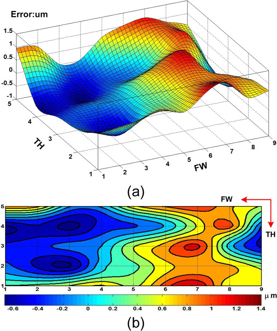
Form error after higher-order modification: (a) error flank and (b) error distribution.
Machine geometric error compensation
After modification comes the final stage where universal machine settings are transformed into control equations of all spindles to execute processing movement and obtain gear production with higher requirements, 24 which means that the modification of the machine settings can directly affect the machine tool spindle movement. An experimental process method is adopted to validate theoretical methodologies which involves two aspects, namely, kinematics transformation between the machine settings and control equation of machine spindles, and makes compensation for the spindle with the maximum error influence.
In this study, a numerical example about the actual machine geometric error compensation is rendered based on the universal machine settings given in Table 1. First, the universal machine tool settings with modification amount are transformed into the spindle control equations of a six-axis CNC hypoid generator YK2050 (see equation (15)) to complete the processing motion of the pinion concave. It can indicate the versatility and correctness of the universal machine settings. And then an experiment about the influence of each spindle on the tooth form errors is performed by sequentially changing the coefficients. Experimental result shows that the A-spindle has the most obvious influence.
The influence of A-spindle with second-order and higher-order coefficients on the tooth flank of the pinion concave is shown in Figure 7. Within the error distribution represented by application of the cubic interpolation, the former can reflect the inclination magnitude between two surfaces and larger variation at both sides of the tooth surfaces along the diagonal direction. For the latter, the magnitude of modification increases at the tooth ends, but decreases at the middle of the tooth surfaces. It is worth noting that the magnitudes of modification on both sides are not balanced, the reason for which is probably that the blade pressure angles are different at the inside and outside blades. 25 It is obvious that such processing result with the A-spindle needs to be enhanced in accuracy by effective geometric error compensation
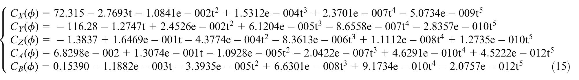
Influence of A-spindle with second-order and higher-order coefficients on pinion concave.
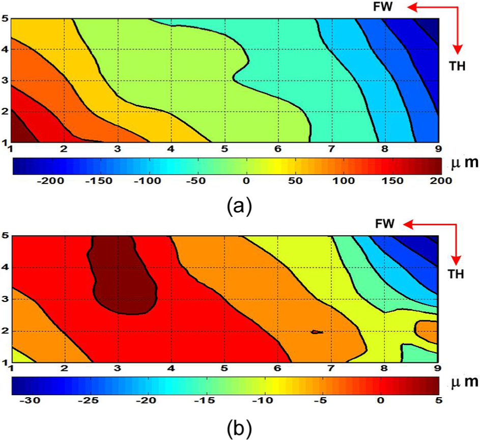
Eventually, the A-spindle with the largest influence is taken as an example to make the compensation for its position error. The Doppler laser interferometer MCV2002+RT-100 rotator is employed to make measurement, as shown in Figure 8. Based on the software error compensation, 26 the spindle positioning error compensation is made by modifying the numerical control (NC) data in the CNC system. The compensation codes are substituted into the CNC system for positioning error correction in movement. Figure 9 illustrates the measurement result before and after the compensation for the processing spindle. The result shows that the maximum angular error is significantly reduced from 0.0044861° before compensation to 0.0009232° after compensation. This fully demonstrates that the proposed method can reduce the tooth form error and effectively enhance gear-processing accuracy for spiral bevel and hypoid gears.
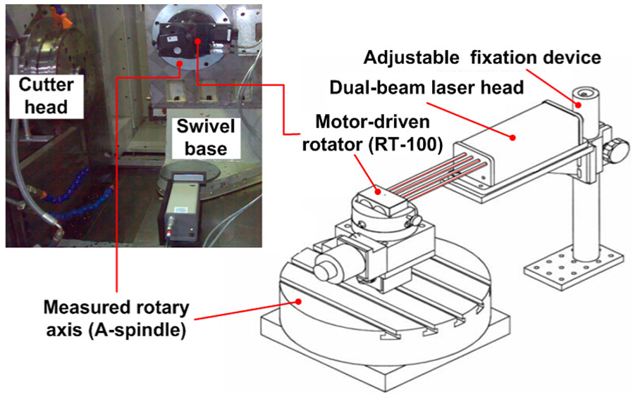
Position error measurement of A-spindle.
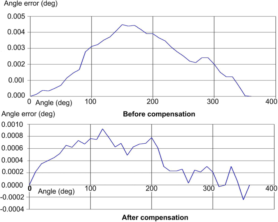
Compensation for positioning accuracy of A-spindle.
Experimental result and discussion
After the universal machine tool settings are modified by proposed methodology, the most important goal is to provide a set of appropriate machine settings for actual gear processing with desirable accuracy and validation check of the real tooth flank by the CMM measurement. According to a closed-loop process scheme elaborated in section “Higher-order modification methodology,” an actual face-milling spiral bevel and hypoid gear is utilized based on a six-axis CNC hypoid generator YK2050. Figure 10 shows a closed-loop process experiment scheme. The related pinion design parameters are described in Table 1. After face milling the pinion, some data about the real tooth flank form error are measured by the Sigma7 CMM. In measurement of tooth flank form error, the predetermined region covering 80% of the face width (FW) and 90% of the tooth height (TH) is discretized by Gleason method. Generally, it adopted the 5 × 9 points grid which generally takes j = 9 datapoints along the FW direction of the surface and i = 5 datapoints along the TH direction according to measurement rules. It is necessary to analyze the tooth error result to judge whether the error meets the requirement or not. If the result fails to meet the requirement, it is a need to make higher-order modification, the actual gear process, and tooth error measurement again and again till the result can meet the requirement.
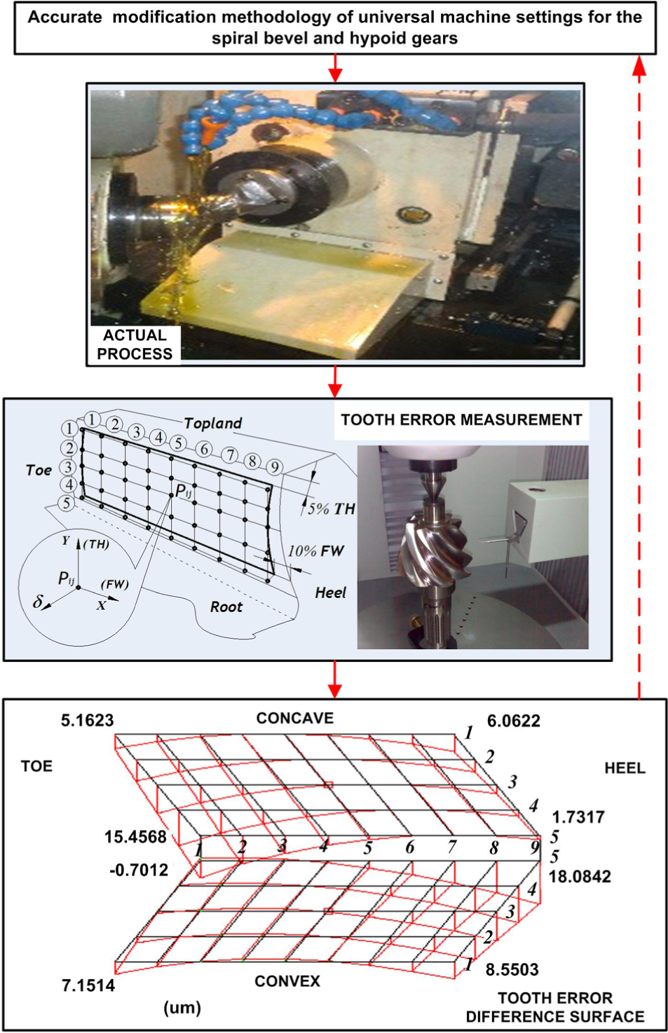
A closed-loop process experiment scheme.
In this article, the experimental result after second-order modification with universal machine settings is provided to check the validation of proposed method. Figure 10 shows the maximum tooth error is 15.4568 µm on the concave and 18.0842 µm on the convex. The RMSEs are 5.02 µm on the concave and 6.34 µm on the convex. As for the difference surface from CMM measurement, error distribution is concentrated at the two ends of tooth flank, while most of the large errors are located in the pinion heel. The result is consistent with the tooth error after second-order modification, as shown in Figure 5. Inconstantly, the actual error value is a little greater than the error calculated in the proposed design method. And to a certain extent, it is rational as there are all kinds of errors with influence on measurement error results in the actual process. As discussed in section “Introduction,” some process error sources including geometry, thermal deformation, tool wear, operation, detection, and other errors in the actual process27–29 are not taken into account in the proposed design. In Suh et al., 30 the error on certain tooth flank can reach about 30 µm after relational modification. In addition, in Fan et al., 16 the RMSE of the tooth flank form error after the second-order modification is 11.4 µm on the convex and 13.2 µm on the concave. A comprehensive comparison indicates that the proposed methodology has desirable validity.
Conclusion
In this study, a kind of higher-order modification methodology of the tooth flank form error with universal machine tool settings to execute processing of the spiral bevel and hypoid gears is investigated with all kinds of machine tools. The mathematical relationship between the universal machine settings and the error surface after modification is obtained to minimize tooth flank form error. The final tooth form error can reach about 0.5 µm by CMM measurement or even a smaller one if it is able to continuously make the higher-order modification. Additionally, a new kind of fitting method is proposed to make the final form error more accurate and more intuitive. Meanwhile, compensation and analysis of the processing error are made for higher-accuracy gear manufacturing. Through observation of the position error of the machine spindles with the proposed modification method, the position error can be reduced from 0.0009° to 0.0003°, which can meet the requirements of accurate manufacturing for spiral bevel and hypoid gears.
Footnotes
Appendix 1
Declaration of conflicting interests
The author(s) declared no potential conflicts of interest with respect to the research, authorship, and/or publication of this article.
Funding
The author(s) disclosed receipt of the following financial support for the research, authorship, and/or publication of this article: This study was supported by the National Science Foundation of China (NSFC) through Nos 51275530 and 51535012 and the National Basic Research Program of China (2011CB706800).