
Abstract
Machine setting modification has been an increasingly important access to the accurate flank manufacturing geometric accuracy control for spiral bevel and hypoid gears. More recently, machine setting driven integration of the theoretical design and the actual gear manufacturing is gaining more and more attention. In this paper, the traditional machine setting modification is extended to the case when higher-order component of the prescribed ease-off flank topography is investigated in form of high-order polynomial expression. Moreover, the actual gear manufacturing and general measurement are integrated into an adaptive data-driven high-order machine setting modification. In particular, this modification method is used to perform adaptive modular control for computer aided process planning (CAPP). Here, a data-driven operation and optimization is developed for adaptive high-order modification. It mainly includes: (i) Polynomial fitting and its optimization by using overall interpolation based on energy method, (ii) Data-driven ease-off flank parametrization based on the fastest descent Newton iteration method, (iii) adaptive control strategy by considering the sensitivity analysis, and (iv) Levenberg-Marquardt (L-M) based approximation for high-order machine setting modification. Given numerical test can verify the proposed method.
Keywords
Introduction
As an increasingly significant stage in design and manufacturing of spiral bevel and hypoid gears, the machine setting modification has always been applied for tooth flank geometric topography optimization and manufacturing precision control. 1 Actually, it aimed to getting an adaptive data-driven micro-geometry optimization approximating to the target flank by considering the prescribed ease-off requirement or CMMs measurement. 2 More recently, with state-of-the-art CNC gear technology, UMC was used to provide the additional freedoms for higher-order parametric expression of machine settings,3–5 as well as tooth flank design. 6 The high-order component of flank topography corresponds to high-order universal motion coefficient of machine settings. Their determination can get an important access to parametric expression of high-order ease-off flank topography by establishing the functional relationships with respect to UMC machine settings. 7 In the traditional modification, the first or second component was only taken into account. Moreover, it only considered ease-off or tooth flank form error used as the basic evaluation criteria. Whereas, in recent high-order modification, the residual ease-off has become an important criteria. 8 Where, ease-off modification becomes a flexible design tolerance between the theoretical design and the actual manufacturing. 9 The ease-off can be prescribed according to user’s requirements 10 and used to determine a target flank in modification. It is undeniable that ease-off flank topography directly affects modification accuracy. Therefore, this machine setting modification considering high-order components is of more versatility, efficiency and flexibility than the conventional modification. However, in recent gear literature, gear designers mainly focused on the numerical solution, 11 CMM measurement, higher-order expression of ease-off flank topography and its geometric topography optimization were developed sparsely.12,13 To improve tooth flank manufacturing accuracy, gear designers firstly paid attention on tooth flank geometry optimization. Firstly, bi-cubic interpolation is employed for tooth flank fitting. Zhang et al. 14 established an accurate tooth flank model by using bi-cubic interpolation. Litvin et al. 15 also employed bi-cubic interpolation to construct tooth flank geometric topography from the simulation generation modeling. Then, B-spline interpolation becomes an accurate tooth flank topography optimization. Artoni et al. 16 and Gabiccini et al. 17 applied a reconstructed tooth flank to get a data-driven optimization of loaded contact pattern. Where, an explicit expression of tooth flank was proposed in a simple form of the parametric formulations. Lin and Fong 18 reconstructed the CMM measured tooth flank by applying a B-spline free form surface fitting method. Actually, in machine setting modification, expect for tooth flank, it is needed to pay more attention on the ease-off flank topography. Here, its target is to minimize the ease-off by approaching to the given target flank as much as possible. 19 Thus, the whole modification becomes an adaptive control where the unknown design variables are machine settings. 20 Ding et al. 21 and Peng et al. 22 proposed NURBS fitting and further optimization for getting a higher tooth flank accuracy. Furthermore, it is very different with tooth flank that ease-off flank topography especially the residual ease-off flank topography is usually shows a higher geometric accuracy. Lin and Fong, 18 tooth flank error was reduced from original 3 mm to 100 µm when control data points were increased from 5 × 8 to 37 ×37 points, and then reduced to less than 0.2 µm by B-spline interpolation. In adaptive modification, 13 RMSE of ease-off flank topography on convex tooth flank after high-order ease-off modification was significantly reduced from 33.8 µm to 1.8 µm. In another published work by Artoni, 12 after prescribing the optimal ease-off flank topography with maximum-to-minimum error value was 60 to −60 µm, the maximum residual ease-off was finally determined as 0.004 µm. It can indicate that the numerical scope of precision evaluation was very small and the geometric accuracy of flank topography itself can deeply affect the numerical result of machine setting modification. Therefore, high-order machine setting modification is needed to pay attention on reconstruction and optimization of tooth flank topography, as well as the ease-off flank topography and residual ease-off flank topography.
In past decades, the first or second-order component of tooth flank from error was usually investigated in tooth lank design.11,13 For instance, in parametric expression, the first component represents the pressure angle error, and the second component represents spiral angle errors. 13 Actually, due to complex tooth flank expression, there were inevitably many error items on the specialized components having the related order and high-order expression. It is of great significance to the actual geometric accuracy control. However, in recent machine setting modification,8,9,11 although high-order modification concept was mentioned, the detailed identification of high-order coefficient of tooth flank topography was rarely investigated.
At the present paper, CMM measurement, machine setting modification and actual NC machining are integrated into an input-to-output modular for CAPP of spiral bevel and hypoid gear manufacturing. To get a data-driven control, an adaptive high-order machine setting modification is proposed. Here, the recent machine setting modification5,8–11 is extended to case when ease-off flank topography in form of high-order expression is modified by determining the accurate universal motion coefficients. To get the ease-off flank topography with high precision and validity, their accurate measurement, fitting and optimization methods are developed, respectively. In the whole modification which turns into an infinite approximation to the target flank.7,12 It means that the prescribed ease-off flank is an important basis for the modification model and solving it for accurate machine settings. Besides, high-order characteristic11,13 is taken into the proposed adaptive high-order modification account. The high-order universal motion coefficients are determined by using the proposed methodology.
Moreover, in consideration of a great similarity of each main process such as rough milling, semi-finishing, finishing and grinding in CAPP, with applications of the high-order modification, an adaptive modular control is also proposed to ensure data-driven control efficiency of the whole CAPP system. It is that high-order modification is very suitable to get an adaptive data-driven control, where machine settings are always main design variables for not only data-driven tooth flank design but also manufacturing. The whole CAPP can become an adaptive data-driven feedback and modification system, 23 where the above high-order modification is applied as a data-driven modular control. Finally, the data-driven operation and optimization method are proposed for the adaptive high-order modification, in order to get an efficient machine setting driven control. In this work, there exist some new features, as follows: (1) New adaptive modular control is proposed to control the whole CAPP for tooth flank manufacturing system. Where, a complex tooth flank manufacturing is performed by correlating with a data-driven adaptive modular control. (2) CAPP considering the whole complex system is effectively achieved by a simple data-driven control modular with respect to machine settings. Here, machine settings are used as design variable in adaptive data-driven control. (3) High-order machine settings modification is investigated by integrating the tooth flank design with manufacturing. 24 With application of the high-order machine settings, high-order characteristic of ease-off flank topography is developed for accurate control of flank geometry accuracy. (4) Data-driven operation and optimization of adaptive control including ease-off flank topography expression and parameterization, control strategy, and L-M based flank approximation. 25 This proposed innovative adaptive data-driven modular control of CAPP by using high-order machine settings modification can significantly improve the tooth flank geometric accuracy and efficiency of spiral bevel and hypoid gears.
CAPP and its driven modular
A basic framework
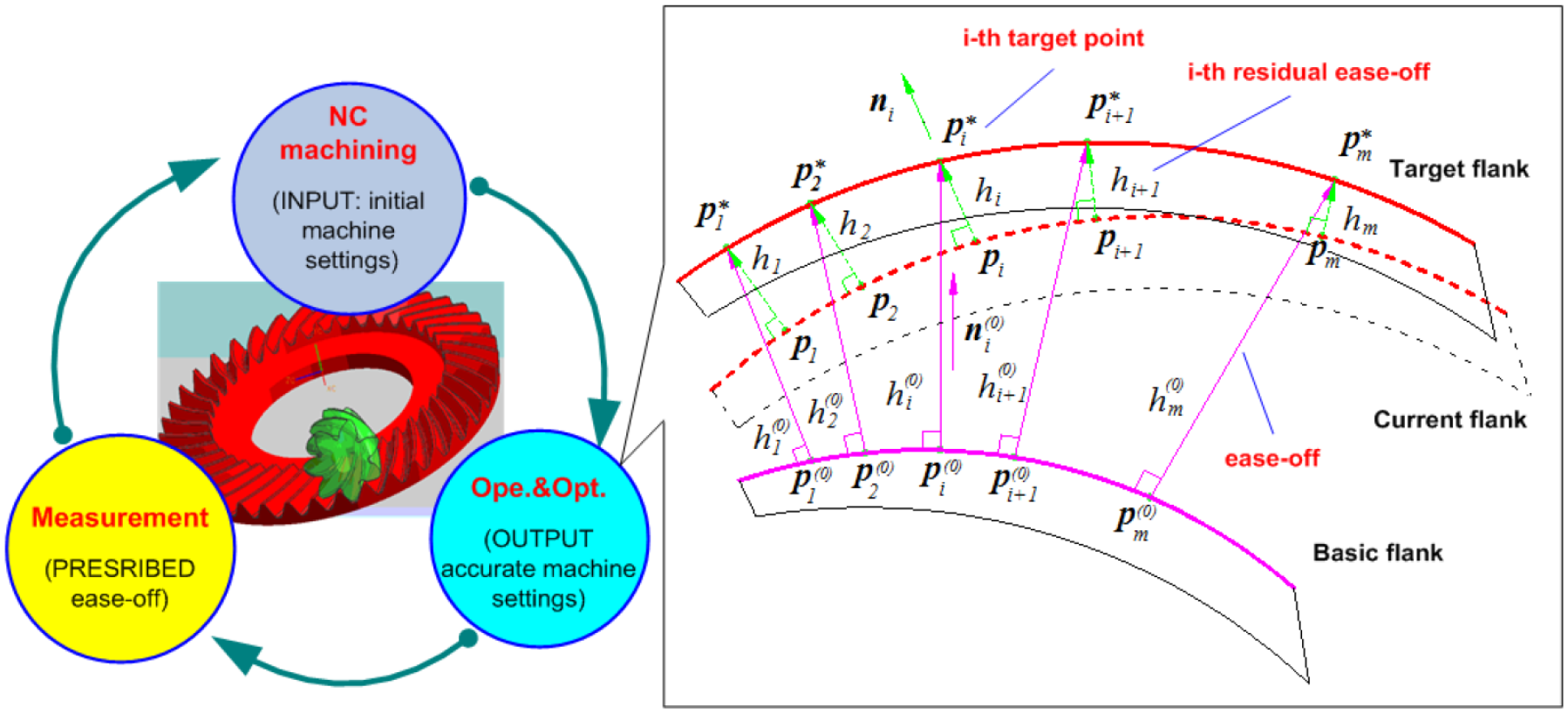
In recent tooth flank manufacturing, data-driven control for the whole CAPP involving multiple processes including face-milling or face-hobbing, grinding and lapping, is rarely studied due to its complexity and difficulty.21,22 In this work, the related manufacturing processes are considered into a closed-loop manufacturing system and a basic modular is established to data-driven control for CAPP. It is well-known that tooth flank manufacturing system for spiral bevel and hypoid gears is very complex. However, for each process, the basic data-driven design variable is the machine setting which can directly affect manufacturing geometric accuracy. To this end, it can provide a basic access to the machine setting modification technique. Figure 1 shows a basic framework of CAPP of spiral bevel and hypoid gear manufacturing system. Here, all processing processes are integrated into an adaptive data-driven system. As shown in traditional planning (in Figure 1), the whole process mainly includes: (i) gear blank design; (ii) machining gear blank; (iii) milling process; (iv) heat treatment process; (v) grinding process. In the milling process, it usually includes different process planning. For instance, it usually uses five-cut method including rough machining, semi-finishing and finishing process for spiral bevel and hypoid gears. 23
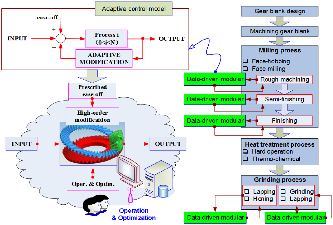
A basic framework of CAPP of spiral bevel and hypoid gear manufacturing system.
In a basic CAPP for tooth flank manufacturing, the same data-driven modular control can be repeatedly for every process. In proposed system, each data-driven modular is an adaptive input-to-output control model which is flexible data-driven design by a closed-loop machine setting modification. To this end, with the same data-driven modular control, CAPP will be of high efficiency to the tooth flank manufacturing.
A data-driven modular
Machine setting modification technique is usually an adaptive sophisticated flank optimization design and can determine the accurate machine settings which are submitted into NC system to execute the actual tooth flank manufacturing.26,27 In traditional industrial practice, the above adaptive determination of machine settings has been completed by a repeated trial-and-error approach requiring experienced or skilled operator. 13 To get an accurate and effective manufacturing, 1 tooth flank design has been closely linked to generate a closed-loop data-driven control system. In this system, design modular is a data-driven feedback and medication towards CNC manufacturing requiring high accuracy and can achieve an accurate process control. Figure 2 represents a data-driven modular of HCIs in the manufacturing system for spiral bevel and hypoid gear by using high-order modification. Here, the high-order machine settings modification8,9 is an advanced computer support cooperative system based on CAD/CAM/CAE/CAPP. In order to get an efficient control, a closed-loop data-driven modular including the following parts:
(i) Manufacturing of spiral bevel and hypoid gears with the initial machine settings,
(ii) Measurement of tooth flank geometric performance after the actual manufacturing, and
(iii) Machine setting modification to provide the manufacturing the basic data-driven variables.
It is worth notation that above three parts are interconnected each other and can be data-driven controlled by determining accurate machine setting. NC manufacturing result is an important input of modification model to obtain the accurate set of machine settings as an output. Then, modification results is also a basic input of the whole tooth flank manufacturing. Here, there are the following data-driven operation and optimization approaches to modeling this integrated manufacturing system:
(i) CMM measurement to prescribe the flank ease-off,
(ii) Polynomial fitting and its optimization to identify the prescribed ease-off flank topography,
(iii) Data-driven ease-off flank parametrization by using the fastest descent Newton iteration method,
(iv) Adaptive control strategy for the whole high-order modification by using sensitivity analysis.
(v) L-M based approximation to complete the high-order optimal machine setting modification.
Adaptive data-driven modular design is actually an application of high-order machine setting modification. Above three parts are also interconnected each other and data-driven controlled by the machine setting. The part (i) and (ii) are integrated into part (iii) and a closed-loop manufacturing model is established. Where, the data-driven operation and optimization is a main task for the proposed high-order machine setting modification. In this work, it will provide an adaptive data-driven design by applying machine setting modification technique.
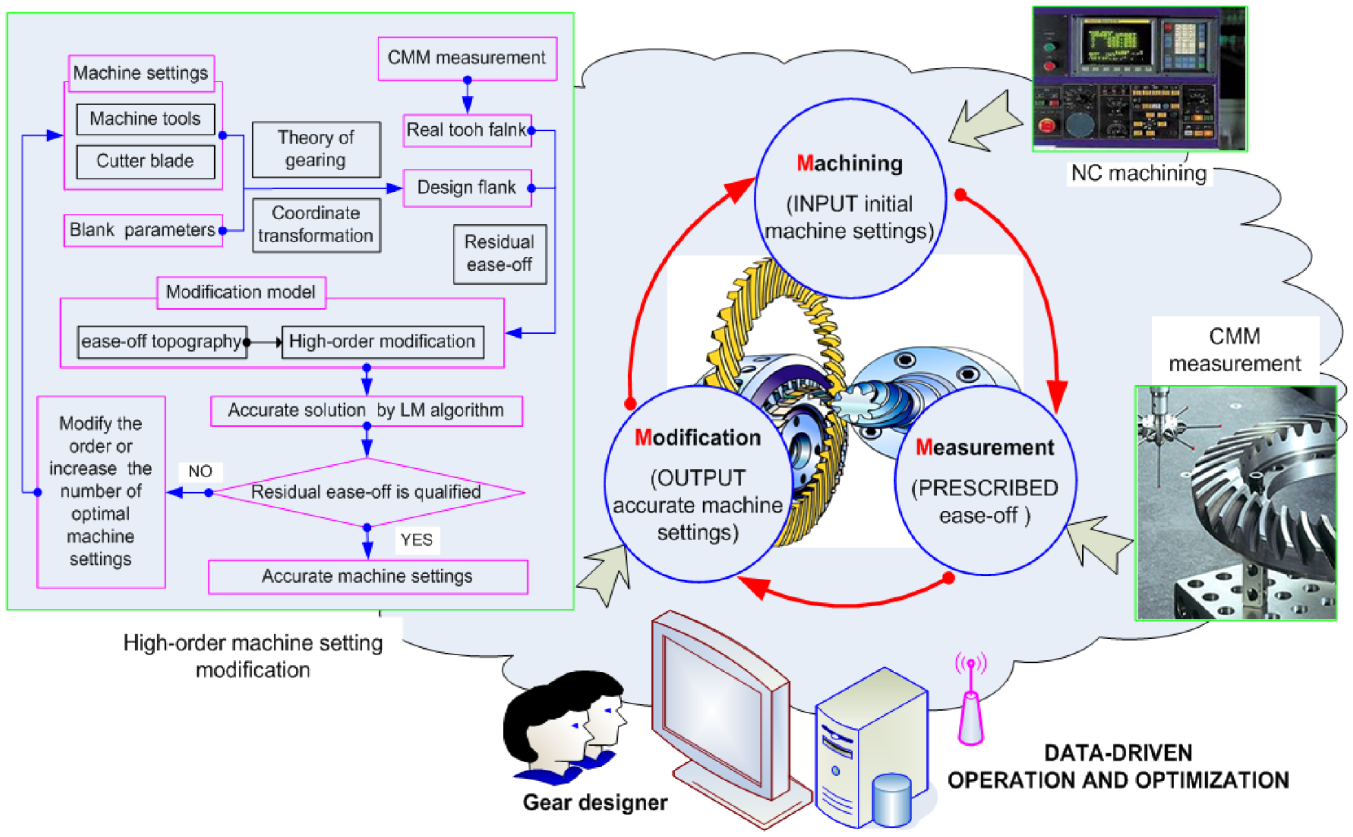
A data-driven modular for computer-integrated manufacturing system of spiral bevel and hypoid gears.
Adaptive data-driven control model
CMM measurement
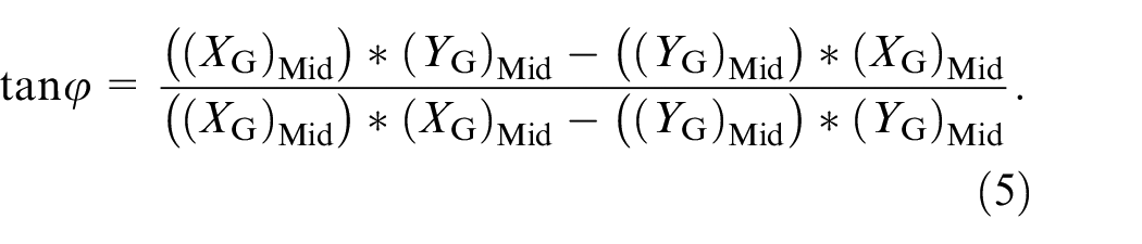
Figure 3 represents a CMM measurement for ease-off flank for machine settings modification. At first, a prescribed tooth flank grid AMBMCMDM which is located the axial cross-section of gear is provided for data-driven measurement operation. And then, measurement positioning process is very important. After determining a point

in this numerical operation, the kinematic transformation is represented
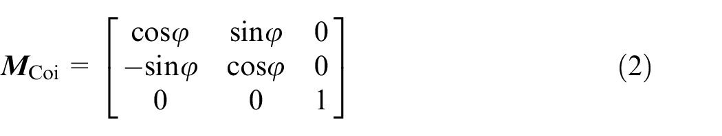
where φ represents the transformation angle.
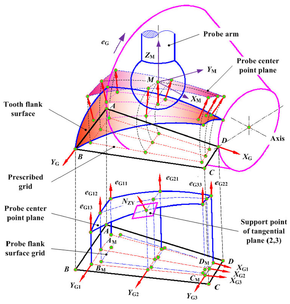
CMM measurement for spiral bevel and hypoid gears. 23
The measured flank grid offsets a distance probe radius RPro in normal direction
Where in order to search for the coincidence point, there exist a data-driven optimization as
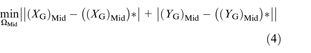
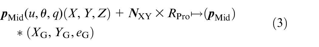
its coordinate is finally determined by using the traversal method. Here, two kinds of coordinate transformations are used to make the probe fall onto the tangent plane of the obtained coincidence point (
Then, a fine modification is performed by the following iterations
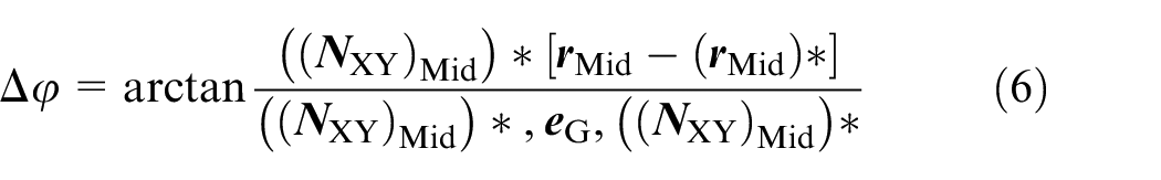
Where, in global coordinate system, tooth flank points (
By running the measurement system program from CMM, the probe automatically approaches to the tooth flank along the normal vector of grid point and coordinates of its middle point is determined. And then, accurate measurement positioning is completed by modifying repeatedly the transformation. Finally, the CMM measurement for ease-off is performed by correlating with the automatic measurement program.8,9
Distinguished with the conventional measurement, if the prescribed grid AMBMCMDM which is design flank
In recent automotive CMM measurement process,
13
it firstly needs to select the probe. For the gear with large pitch angle, if the normal vector of each grid point can satisfy
Adaptive model
Adaptive design for tooth flank manufacturing presents HCIs and self-innovation process regarding to the machine setting driven operation and decision. According to the input intention of the designer, the geometric model of the potential feasibility design plan is generated through the “adaptive” system, and then comprehensive comparison is conducted, and the design plan is filtered and pushed to the designer for final decision. In this work, in consideration of the intention or requirements from the gear user, an adaptive high-order modification is proposed. Actually, the adaptive machine setting modification is also a flexible approximation of the prescribed target flank. It is needed to match the target flank having the prescribed error threshold6,8,9 satisfying the user’s requirements. In full consideration of the integrated optimization design with manufacturing, a new medium flank is provided to show reliability and accuracy of the proposed data-driven adaptive model. In Figure 4, ease-off flank is determined as a target and the residual ease-off is used as an evaluation criterion on adaptive data-driven modification. In the determination process of the ease-off flank topography, it can be configured for some requirements of geometry performance from gear user or manufacturer.
Adaptive control model by using high-order machine setting modification.
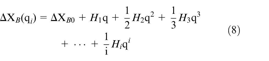
Furthermore, UMC universal machine settings3,8 having the high-order motion coefficients are selected as design variables. 9 In UMC framework, 8 high-order machine settings including Sr, EM, XB, XD, γm, σ, ζ, and Ra all can vary during gear generation as polynomial functions of the cradle rotation angle q which acts as the motion parameter.6,12 For instance, EM is just the constant term of their corresponding UMC polynomial representing the vertical motion, 16
XB is just the constant term of the UMC polynomial representing the helical motion, 12
With application of high-order machine settings, they can establish tooth flank model as
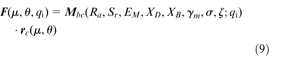
Since the establishment of tooth flank is an envelope of the curve family, each flank point
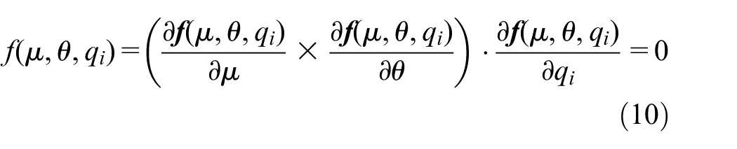
in partial differentiation with respect to the individual components of (µ, θ, qi), the cross-product item determines the normal to the moving tool surface, whereas ∂
With providing an accurate and robust algorithm, this modification only needs one or two times to satisfy the given requirements. With accurate numerical solution for matching the established high-order modification model, this adaptive data-driven design actually is an integrated design involving to the whole process.
12
The basic tooth flank with m data tooth flank points

In the present paper, any modification of tooth flank geometry with respect to basic design flank is called ease-off hereafter.
6
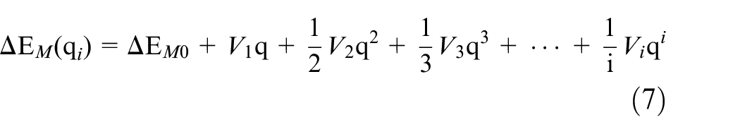
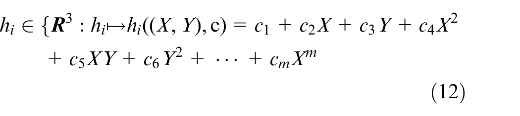
These ease-off points can construct ease-off flank topography. Here, as standard of limited approximation degree for a target flank, i-th component hi∈
Apparently, some flank micro-geometric topographies as its primary components play important roles for the whole adaptive modification process. In particular, ease-off flank topography is a target flank while a basic initial value to solve the objective function is determined for accurate machine settings with modification variation. The ease-off value is usually prescribed point-wise by referring to manufacturing geometric accuracy requirement.6,8 To establish an accurate modification model, ease-off points has to be fitted into parametric flank topography in closed form. Especially, in the consideration of fine-modification with higher accuracy, 9 the computational accuracy of adaptive high-order modification itself will directly affect the whole modification process.
Operation and optimization of adaptive control
In full consideration efficiency and accuracy of the proposed modular control, data-driven operation and optimization is applied in the adaptive high-order machine setting modification. Where, some new keys to the proposed adaptive data-driven modular control are developed, respectively.
High-order expression of ease-off flank topography
Now, a polynomial fitting method is used to give an explicit expression for ease-off flank topography and make it available in closed form. Moreover, this method can show the following main advantages:
(i) the polynomial fitting topography is continuous and easy to complete recursive formulation6,7;
(ii) it is easy to correct flank topography by an accurate functional expression while it needs a repeated modification or optimization,
(iii) flank topography can be defined over the [0,1] × [0,1] domain which entails advantages while choosing initial guesses for numerical formulation.12,16
Here, polynomial fitting method is employed for fitting ease-off flank topography after sampling tooth flank points by CMM. Thus, it can provide an accurate input to the whole modification process. With the given m·×·n points as the prescribed flank grid, the ease-off flank topography referring to Gleason method 11 is represented as
with CMM measurement, (X, Y) is known and hi ((X,Y),
Generally, ease-off usually required by 0.01 mm order13,18–20 in machine setting modification. In some special industrial applications especially for aerospace gear transmission, it is always required the higher accuracy. Taking into account the singular data points in above described extraction, it is needed to optimize the ease-off flank topography after fitting to achieve adequate smoothness. Additionally, this optimized flank can provide a basic data-driven model for TCA or NTCA and make them gain an effective tooth contact performance evaluations. 21
Then, in order to obtain a higher accuracy and a better flank smoothness of ease-off flank topography, overall flank topography interpolation based on energy method is used as a data-driven optimization scheme in adaptive high-order modification. An adaptive data-driven objective function can represent the smallest strain energy of the tooth flank. Their control point are set as a variable and solved for the data points in the smallest strain energy position. By setting the strain energy
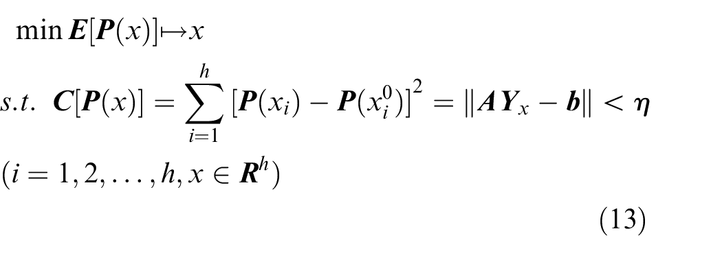
where the objective function
Herein, the strain energy can be represented as 28
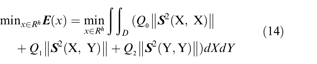
Combing with some related equations, the above equation can be transformed into the quadratic programming problem to be solved. 29 By substituting the equation (12) into equation (14), there is

Meanwhile, the linear equations can be established as

where, the unknown data points are assumed as x, their coefficient matrix is Kx and their vector is
Combining with equations (15) and (16), there is
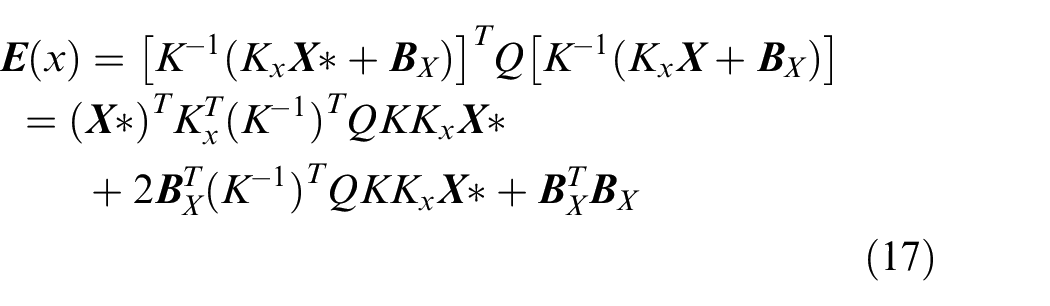
As this is the quadratic programming problem, so its optimal solution is required to meet

Finally, a new residual ease-off flank topography having the minimum strain energy is obtained by solving equation (18).
High-order topography parameterization
After accurate high-order expression of ease-off flank topography, Newton iteration method is applied to get a uniformed parameterization. By selecting the projection points of ease-off flank grid, the point having the minimum distance from the ease-off flank is determined and its value is used as an initial reference of solution for the target points. Here, the parametric ease-off flank points must be met during this mapping process
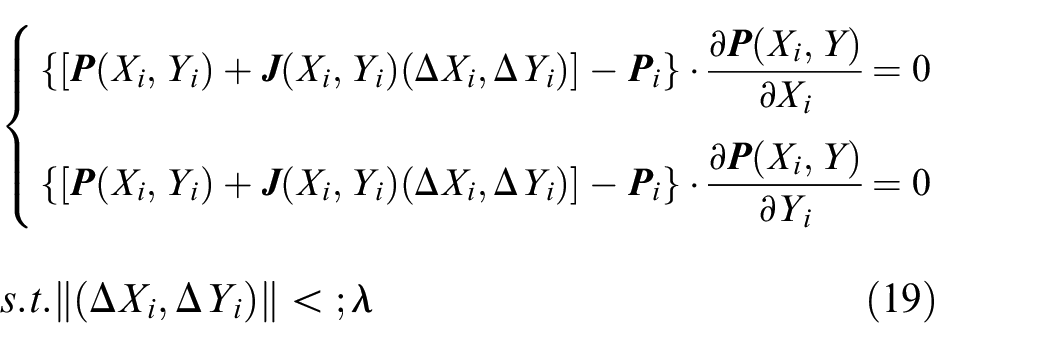
Where,
In consideration of continuity and versatility, the target flank point has the same direction with the original ease-off flank. In order to get an accurate solution, a fastest descent method with Newton iteration step is employed. Firstly, the grid is divided into equal parameter curve families to obtain the coordinate parameters of each grid node. Then, the parameter value of the grid node which is closest to the data point is used as the initial value, and the iterative search operation is performed to complete accurate parameterization of the data point. Comparisons in the X-direction and the Y-direction are made respectively, and their final distance are sued the penalty function values.
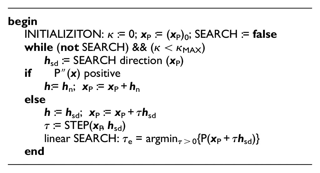
In order to perform Newton iterative search, it is required to take a stable point
Search iteration step
Next step is

Assuming that H is positive, it has non-singularity and all non-zero u satisfy

notes
After the Newton step is determined, it is used in the fastest speed descent method to perform parameterization of the tooth surface. When
Adaptive control strategy
In recent machine setting modification, its nonlinear solution is very complex and time-consuming.30,31 The main reason is too many machine settings as the unknown variables. Because machine settings are coupling with each other and these relations are always are blurred and powerful.
However, in general modification,5,6,32–34 all machine settings
Figure 5 shows the adaptive modular control strategy for driven machine settings based on sensitivity analysis. Firstly sensitivity of each machine setting is calculated as
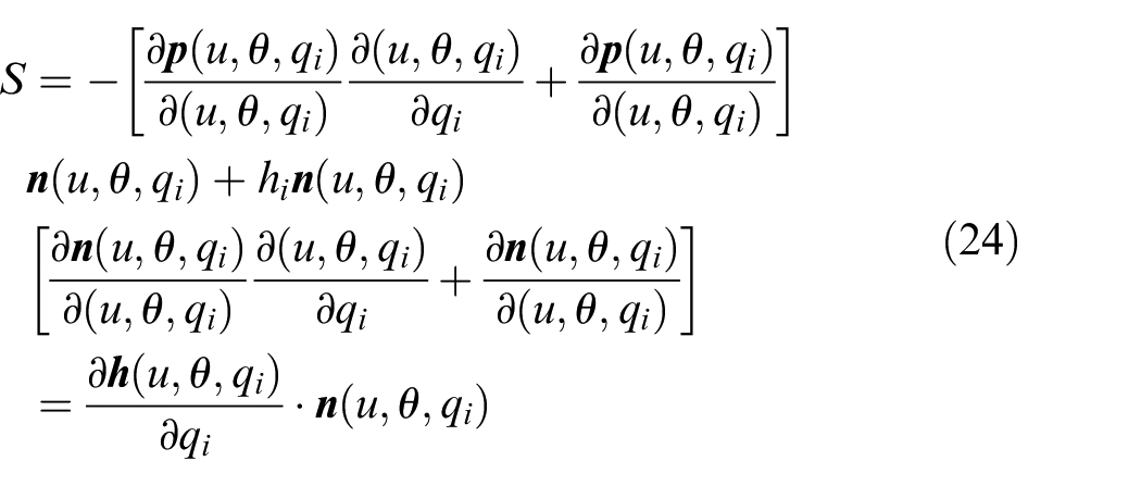
S represents the sensitivity coefficient of machine setting.
30
Here, the machine settings having the large sensitivity coefficients are selected as the unknown design variable for the proposed modification. Generally, their number n is less than 5. As for the basic input namely the initial machine settings, the adaptive high-order machine setting modification is performed to determine the accurate machine setting
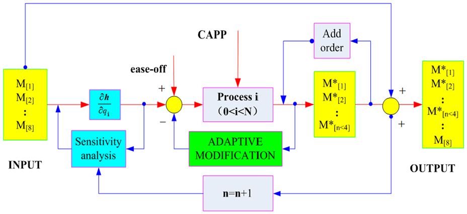
Adaptive modular design strategy for machine settings driven control.
L-M based flank approximation
In proposed adaptive control design, a high-order machine settings modification is essentially a finite approximation to the prescribed target flank satisfying an accurate parameterization.35,36 To get an accurate modification, L-M based flank approximation is proposed. With the proposed polynomial fitting and optimization, the ease-off flank is provided, as well as initial high-order coefficients. With the given initial
is linear function about
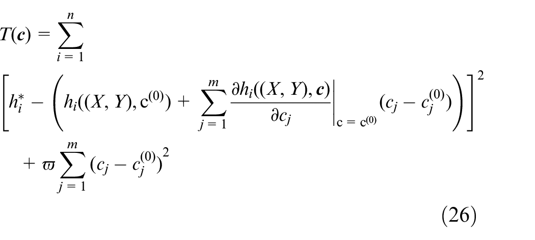
ϖ is the damping factor. For minimizing the objective, its first partial derivative with respect to
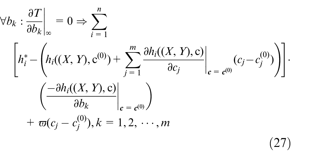
with the transformation, there is
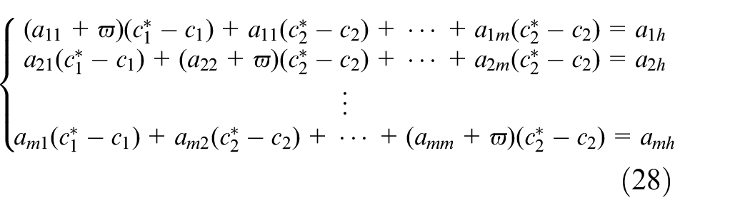
where
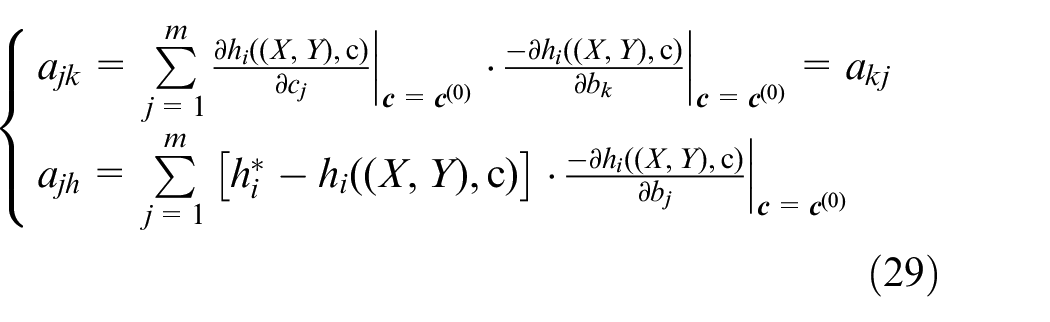
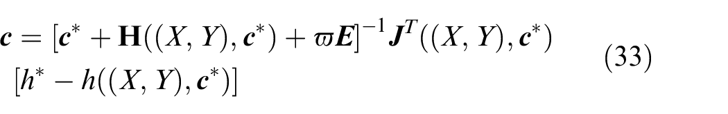
the solution can be obtained as
In this solution, there exists the Jacobian matrix, namely the first partial derivative objective function
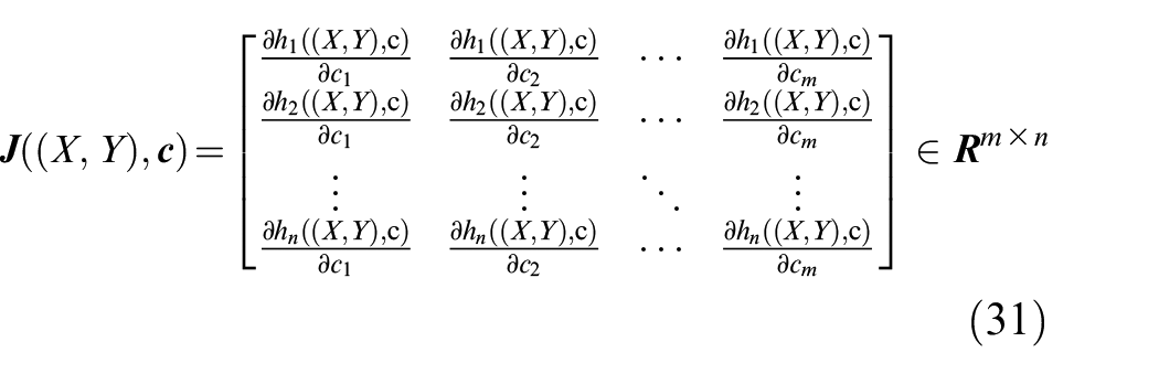
can be simplified as

there is
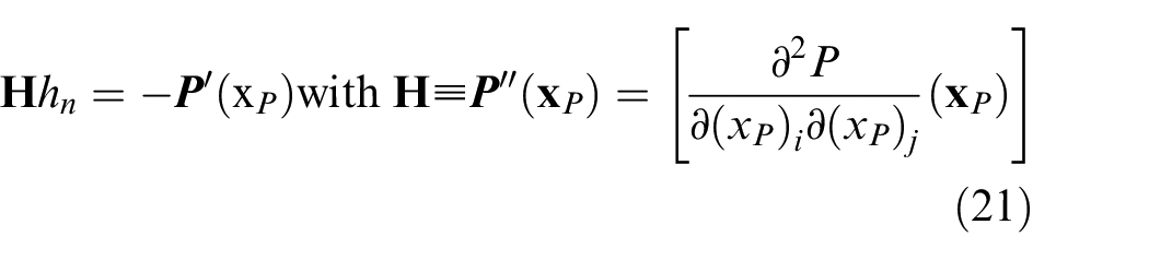
It is the iteration formula of L-M algorithm. Thus, it is can be solved by L-M algorithm and its basic outline of the algorithm as follows:

the iteration step
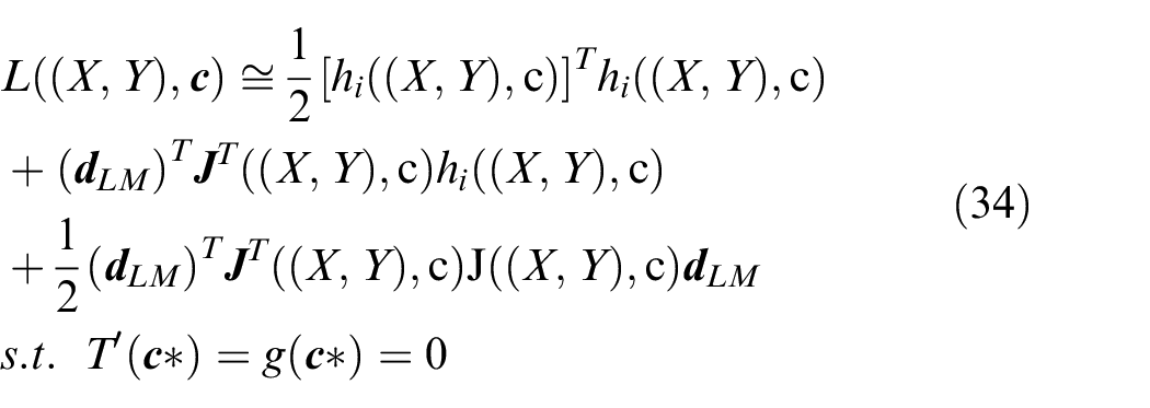
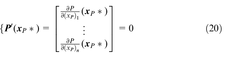
The stopping criteria for the algorithm should reflect that at a global minimum it assumes that T’(
Numerical test
Basic design
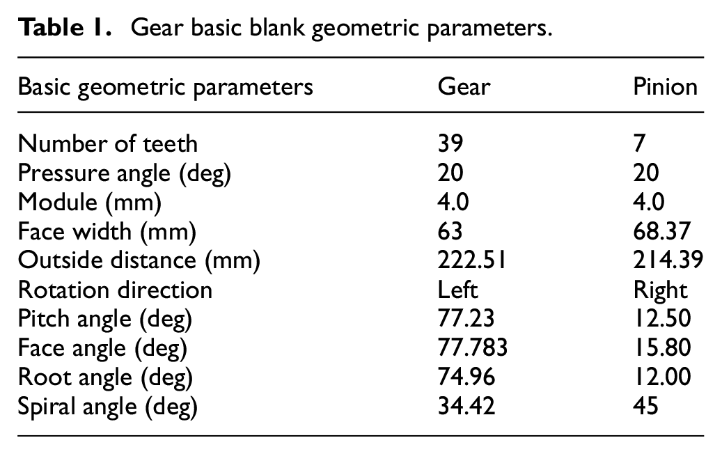
Now, a real Gleason face-milling hypoid gear drive is applied in automotive drive axle transmission. In the actual manufacturing, Tilt® approach is for pinion flank and Generated® approach is for gear flank. 24 Hypoid generator is Gleason No.116 having the cradle mechanism and tool tilt device. Table 1 provides the basic blank design parameters for tooth flank modeling of hypoid gears.
Gear basic blank geometric parameters.
Due to the similarity and repeatability of the proposed data-driven modular control, a basic finishing in face-milling process is taken into account. Its basic matching settings is used to perform the proposed adaptive high-order machine setting modification.8–10 The other processes in CAPP of the integrated manufacturing for spiral bevel and hypoid gears such as the grinding and lapping process are performed by correlating with the similar applications.9,13
CMM measurement
Generally, basic target flank satisfying the prescribed tooth flank form error is determined by according to CMM measurement evaluation. In industrial practice, a prescribed tooth flank form error can be obtained by CMM and then measured data points are fitted into flank topography. Generally, the tooth flank form error can be obtained by the commercially available software packages such as G-AGETM and KOMET®. 6 In a universal CMM measurement according to Gleason method, the tooth flank is made discretization by a typical 5 × 9 points grid, which generally takes 9 data points along the face width (FW) direction and 5 data points along the tooth height (TH) direction according to the Gleason measurement rule, 11 respectively.
Figure 6 represents coordinates of the prescribed flank surface gird points. Where, the initial contact point as the initial positioning point in CMM measurement is represented by a five-pointed star. To get a high flank geometric accuracy of adaptive high-order machine settings modification, the number of tooth surface sampling points is generally as many as possible. The sampling points are the ones belonging to both active flank and tooth fillet. It is worth notation that the selection of basic coordinate center is of large importance to identification of flank discretization.
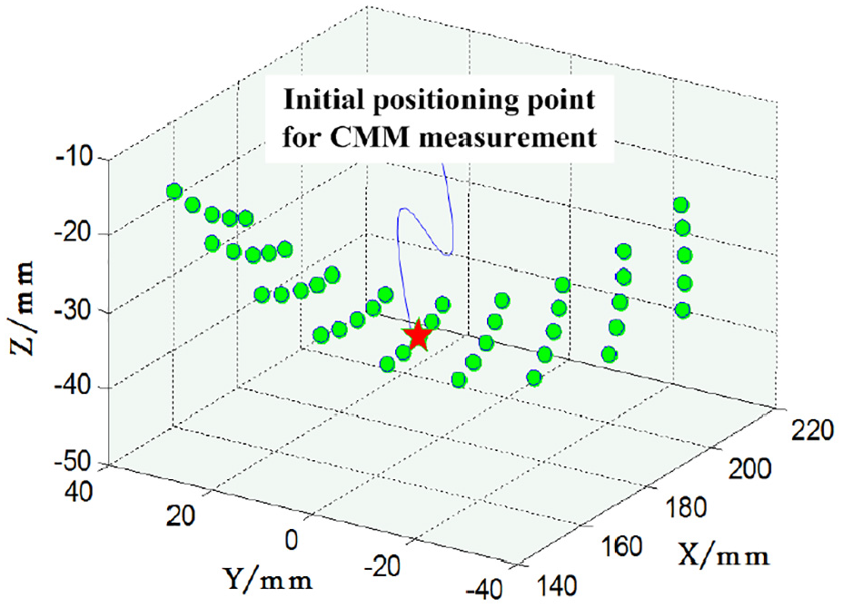
Coordinates of the prescribed flank surface gird points for CMM measurement.
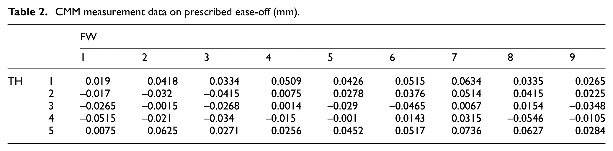
In modification model, ease-off on each tooth flank grid point can identified by CMM measurement for the actual processed gear flank,16,17 and then they can output to be fitted into a ease-off flank topography as a target flank by the proposed polynomial fittings. As shown in Table 2, it provides certain a CMM measurement data on predesigned ease-off which can reflect user’s geometric requirement. Where, small ease-off mainly lay in middle area while RMSE of ease-off is 38.26 µm and the maximum is 73.6 µm and the minimum is –51.5 µm. Of course, ease-off flank topography also needs to be identified according to requirement on physical performances.
CMM measurement data on prescribed ease-off (mm).
High-order topography expression
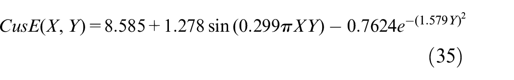
Here, the output ease-off points from accurate CMM measurement evaluations are used to perform the polynomial fitting. In four interpolation methods, the cubic and nearest neighbor has a better goodness of fit because of SSE is 0 and R-S is 1 and the whole RMSEs are NaN which entails shortcoming for the fitting accuracy. In the lowess fittings (robust: off and span: 25%), the quadratic is better than the linear method. Furthermore, Figure 7 shows some ease-off flank topographies of four main kinds of interpolation fitting methods. Though the nearest neighbor method has a better goodness, ease-off shows ladder-liked distribution and is not continuous. In ease-off flank topography fitted by quadratic lowess method, fitting surface is also in lack of good recursive formulation. Here, tooth flank is also not continuous and differential where errors change significantly. Considering the data in Table 2, the custom equation can be represented into
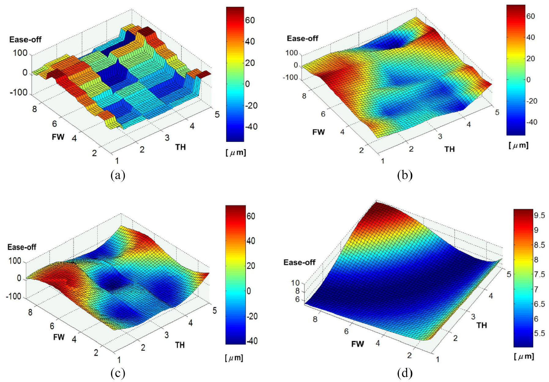
Ease-off flank topography comparisons of four main kinds of interpolation fitting methods: (a) nearest neighbor interpolation, (b) cubic interpolation, (c) quadratic lowess (span:25%; robust: off), and (d) custom equation.
However, this method has an obvious default that its error distribution seriously deviate from the actual measurement data as shown in Figure 7(d). By comparisons of four fittings in Figure 7, ease-off flank topography in applications of the cubic interpolation method is the best one. Results on the cubic interpolation are better than other three interpolations by considering a higher goodness of fit, in addition to other characteristics such as the topography smoothness, continuous, and functional expression.
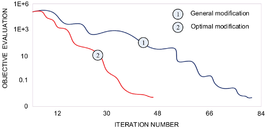
Computational efficiency comparisons of the different modifications.
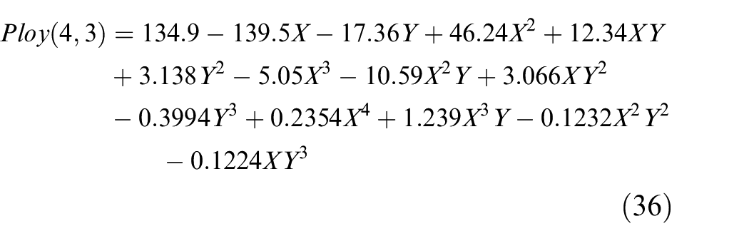
With obtaining the given data points of ease-off flank topography, Table 3 represents the goodness of fit by using the proposed polynomial fitting methods with different orders about X and Y. In above polynomial fittings, while the order of X is 4 and Y is 3, there is the best goodness of fit. This polynomial function is represented as
Goodness comparison of polynomial fitting methods.
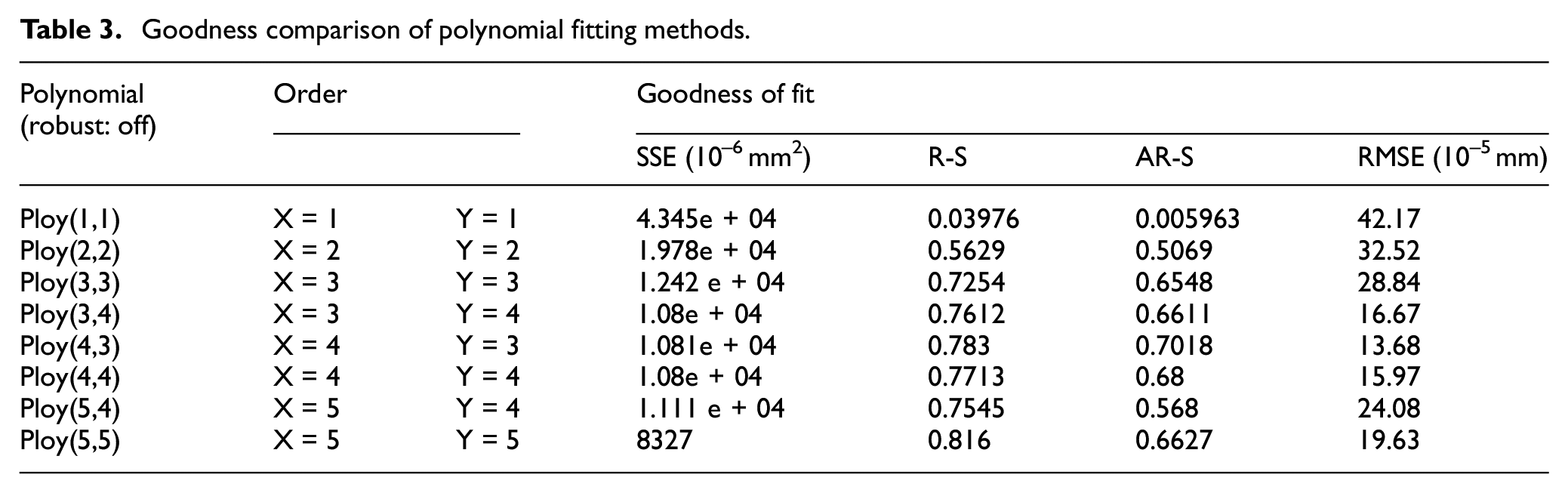
where, the coefficients are within 95% confidence bounds. There are 5 × 9 data points sampled on the target flank which are used to calculate the ease-off to the basic flank from the CMM measurement.
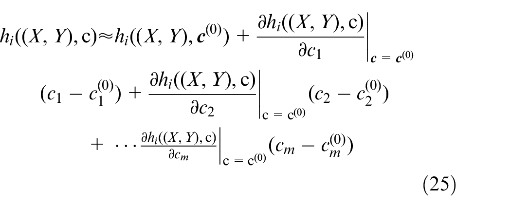
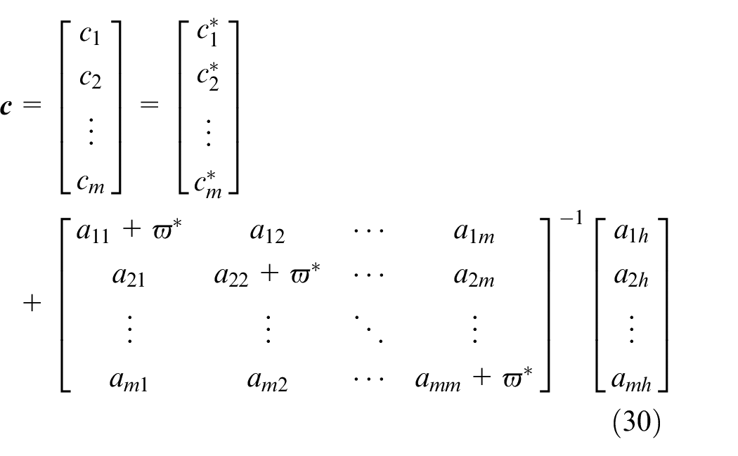
In the conventional modification, it generally only considers the two order ease-off flank topography
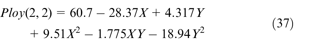
c1 = 60.7 represents the initial normal deviation at the reference sample points, c2 = -28.37 and c3 = 4.317 represent the pressure angle and spiral angle errors, respectively; c4 = 9.51, and c5 = −1.775, represent second-order errors in profile, warping, and lengthwise curvatures. 23
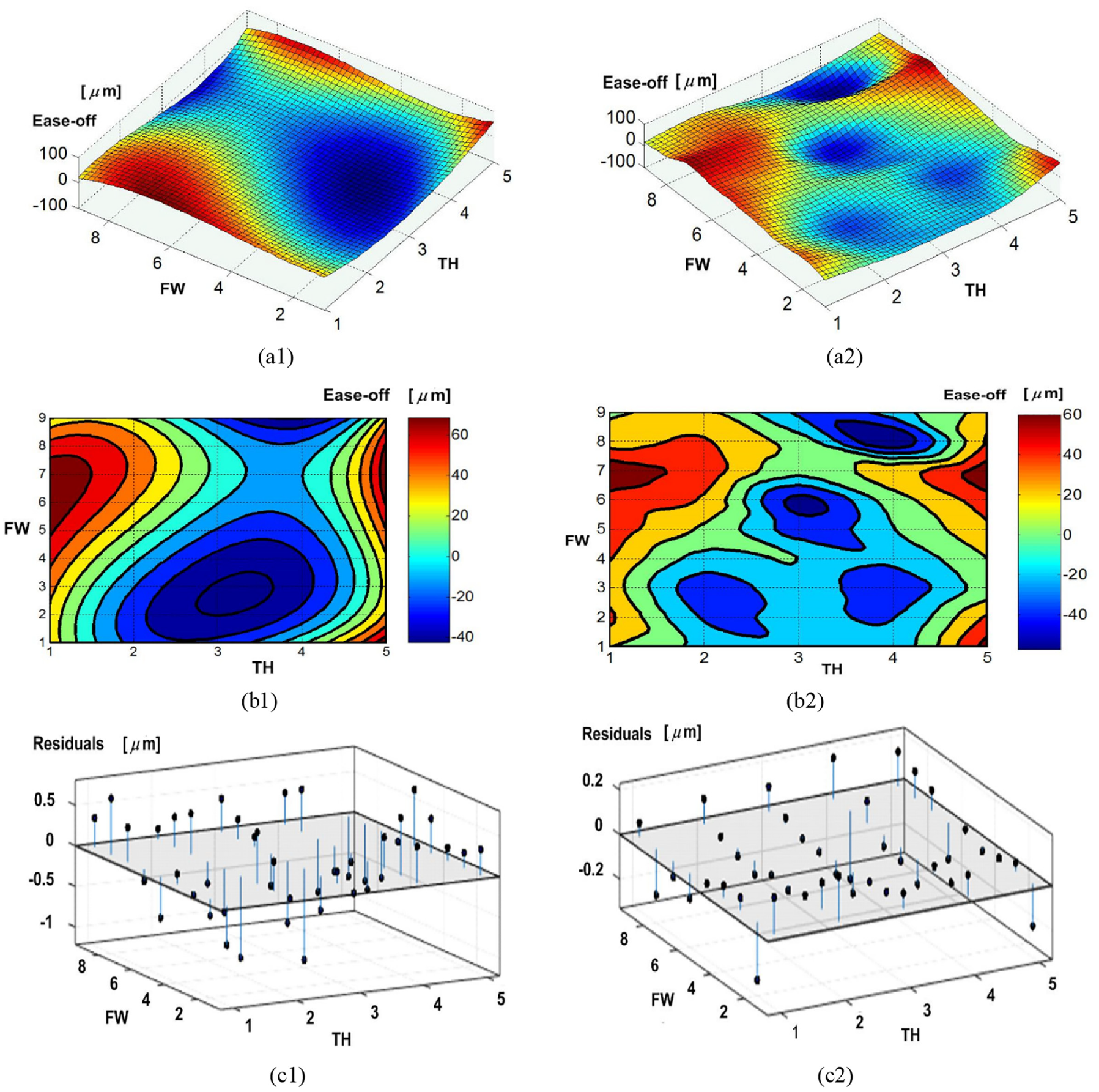
Figure 9 shows comparisons of conventional Ploy(2, 2) and the proposed Ploy(4, 3) using the overall interpolation based on energy method. In optimization, the corresponding parameters are set as λ = 10–6 mm and η = 10–8 mm, respectively. Where, with respect to the ease-off flank topography and distribution, Ploy(4, 3) is obviously better than Ploy(2, 2) by correlating to the actual measurement value about the ease-off. Besides, as for the fitting method itself, the residuals at each fitting points have obvious differences. For instance, in Ploy(2, 2), its RSME is 0.3252 µm while the maximum is 0.516 µm and the minimum is –0.934 µm; in Ploy(4,3), its RSME is 0.1368 µm while the maximum is 0.2045 µm and the minimum is –0.2347 µm. It can indicate that higher-order polynomial fitting of ease-off flank topography in modification is of higher accuracy and validity. Now, the identification of the prescribed topography considering the user’s requirements in the adaptive design can put an input for the adaptive modification.
Ease-off flank topography with polynomial fittings: (a1) topography, (a2) distribution and (c1) residuals for the Ploy(2, 2); and (b1) topography, (b2) distribution and residuals for the Ploy(4, 3).
L-M based approximation
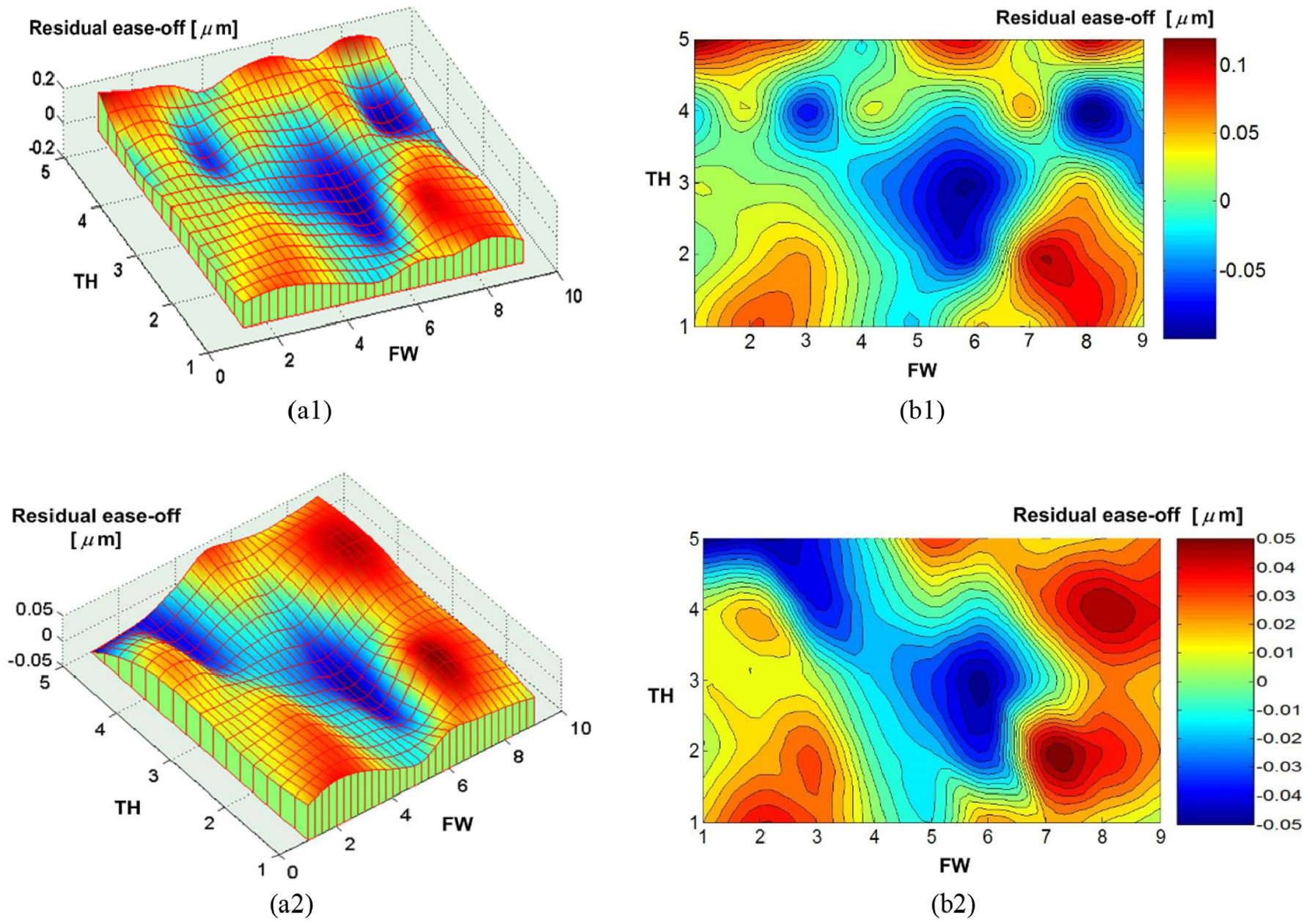
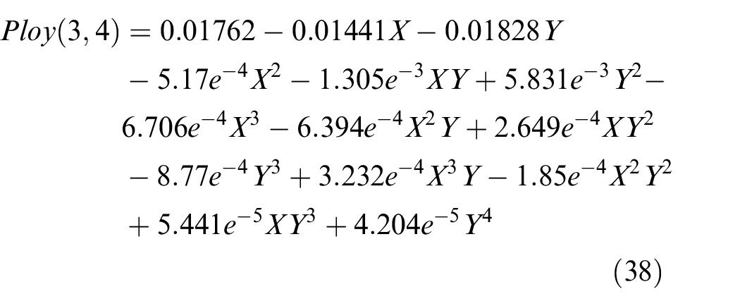
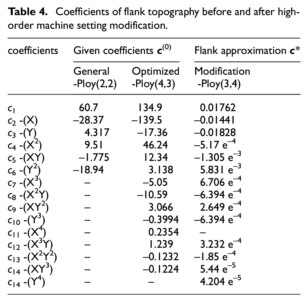
In high-order modification, the target is to get an accurate approximation of target flank considering the prescribed ease-off. Here, it is performed by correlating with L-M based approximation method. It is worth notation that some coefficients on stopping criteria in application of L-M algorithm are always set as υ = 10−4, ε1 = 10−7, ε2 = 10−8. Figure 9(a1) and (b1) represents high-order modification results in form of the residual ease-off flank topography and residual ease-off distribution. Here, RSME of residual ease-off is 0.0352 while the maximum is 0.1356 µm and the minimum is −0.09464 µm. The large error is mainly concentrated at middle area, and the corner approaching to toe and root position. Table 4 shows a high-order coefficients of flank topography before and after high-order machine setting modification. In particular, with comparisons of fittings with the different orders, while the order of X and Y are 3 and 4, respectively, fitting topography has the best goodness, which can expressed as
Coefficients of flank topography before and after high-order machine setting modification.
the goodness of fit is that SSE is 3.489 e–5 µm2, R-square is 0.9288, adjusted R-square is 0.893, RMSE is 1.061 e–5 µm. Obviously, this method can provided a good foundation to higher-order modification with high accuracy.
Additionally, to get a higher accuracy, residual ease-off flank topography after polynomial fitting is improved by using the proposed optimization method. In this optimization, flank topography is firstly made parameterization to obtain a uniform expression and then overall interpolation to improve the accuracy, where the λ is set as 10–6 mm and η is set as 10–8 mm. Figure 10(a2) and (b2) represents residual ease-off flank topography after proposed optimization. RSME of residual ease-off is 0.0184 µm while the maximum is 0.05152 µm and the minimum is -0.05037 µm. The large error is mainly concentrated in middle area and in the corner approaching to the flank boundary. By comparing with the error distribution after polynomial fitting, the whole tooth topography accuracy has significantly improved. Moreover, the comparison results can show that RSME is reduced by 47.7% while the maximum (MAX) is reduced by 62% and while the minimum (MIN) is reduced by 46.8%. Moreover, residual ease-off flank topography is of good smoothness.
Residual ease-off result comparison for the proposed methods: flank topography (a1) and its distribution (b1) after polynomial fitting; flank topography (a2) and its distribution (b2) after proposed optimization.
As further proof, numerical results of the proposed methods is comparing with relative optimal results in previous literature about tooth flank geometry optimization in ease-off flank topography. This work of higher accuracy than the optimal results that RSME is 1.8 µm after high-order ease-off flank topography in Fan et al. 13 (see introduction part) and the maximum finally is 0.67 µm after modifying the alternative set of machine parameters in Ref. 12 published by Artoni. Moreover, though this result is lower than the most optimal result that is the maximum finally is 0.004 µm after modifying the set of redundant parameters in Ref. 12 Considering advantage of whole solution process, such as there are 17 machine settings selected as design variables and it converged successfully after 91 iterations, this proposed methodology is also reach the same accuracy if we can improve the computational accuracy in this machine settings modification or change the other numerical test. Thus, the tooth flank geometric accuracy in this work is sufficient because the order of 1 µm is obviously insignificant to the gear manufacturing in practice.
Optimal control output result
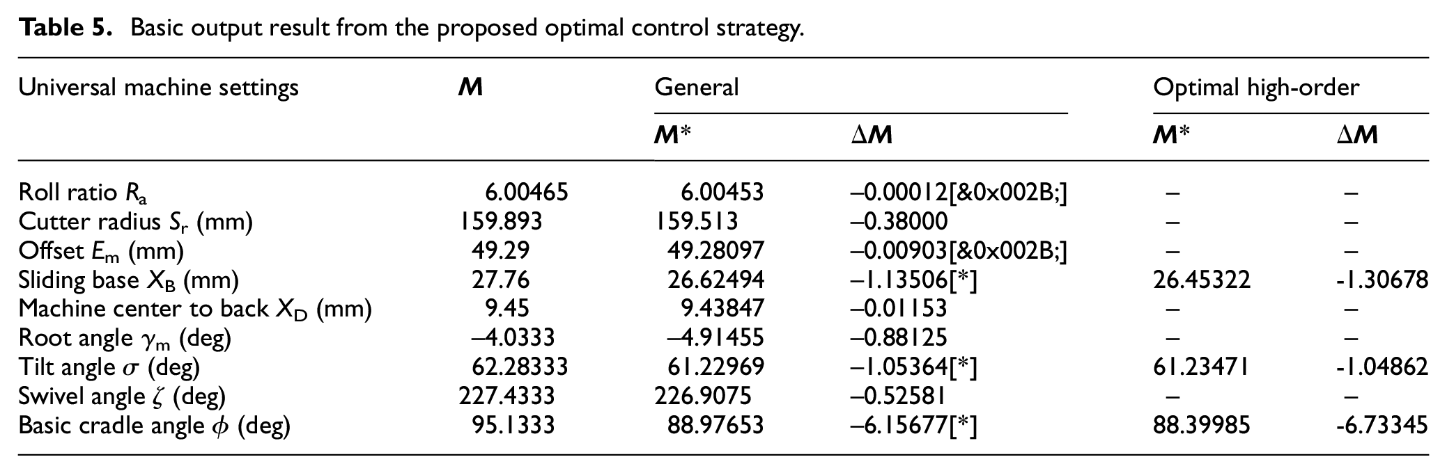
Table 5 shows a basic output result from the optimal control strategy of the adaptive data-driven modification. Here, with application of sensitivity analysis, XB, σ and ϕ are selected as optimal machine settings marking by [*] and adaptive high-order modification is performed to determine the accurate machine setting settings
Basic output result from the proposed optimal control strategy.
Experimental results
With the optimal control output result, accurate machine settings are submitted into the hypoid generator to perform the actual face-milling of the hypoid gears. In order to show an adaptive data-driven modular design for a certain process, Figure 11 shows a basic CAPP for pinion face-milling including the rough milling, semi-finishing and finishing. Here, in consideration of complex process, the rough milling and semi-finishing employ a continuous indexing method, and the finishing can employ the single indexing method for the concave and convex flanks in order to get a high precision accuracy. Figure 12 shows the CMM measurement result on the pinion tooth flank form error on concave flank. The RMSE of the tooth flank form error is 0.01028 mm while the maximum is 0.382 mm and the minimum is 0.0003 mm. According to the actual manufacturing requirement on tooth flank manufacturing geometric accuracy, this tooth flank form error can shows a high accuracy.
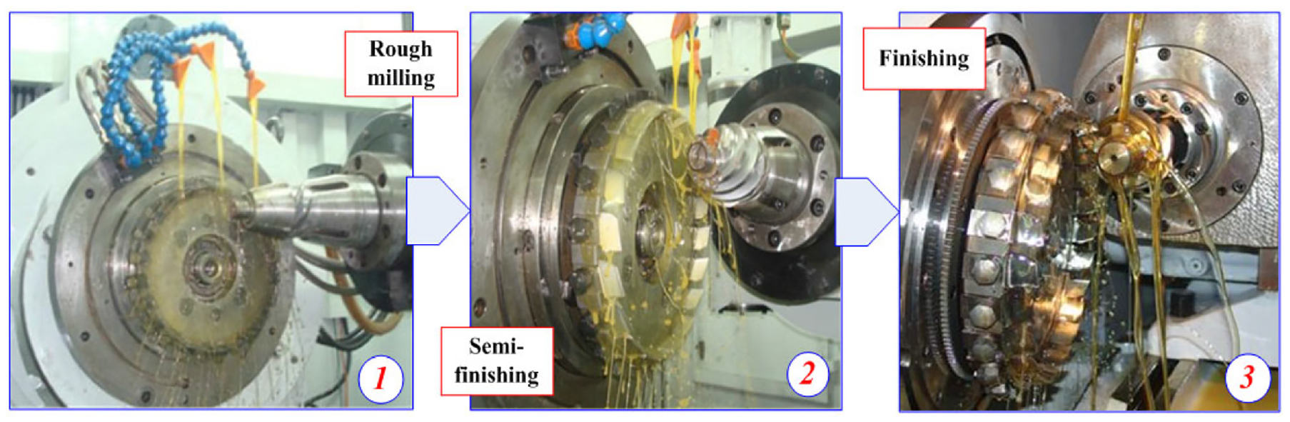
The basic CAPP for pinion face-milling: rough milling + semi-finishing + finishing.
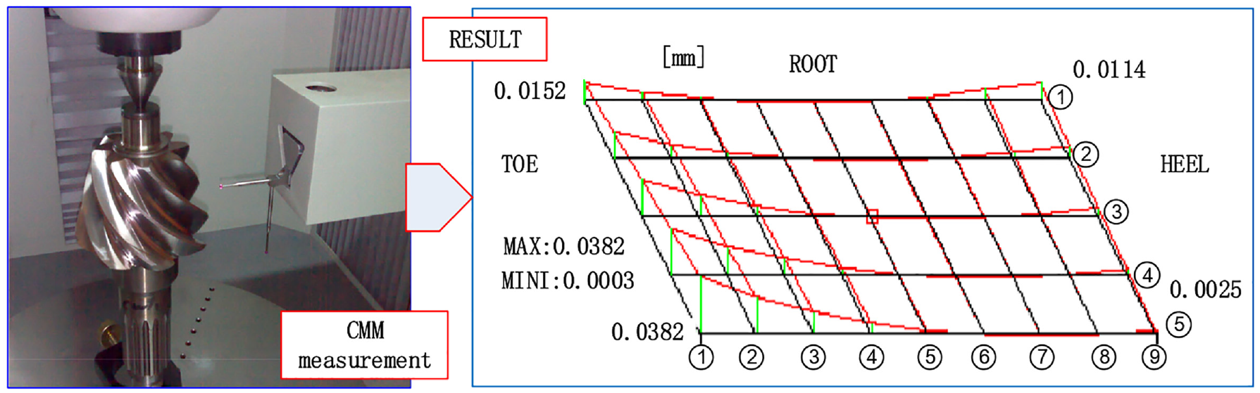
CMM measurement result on the pinion tooth flank form error.
Conclusion
Considering integration of the theoretical design and actual manufacturing, high-order machine setting modification is applied to get an innovative adaptive modular control of CAPP for a closed-loop manufacturing of spiral bevel and hypoid gears. There are several distinct data-driven control methods as follows.
(i) An accurate data-driven modular for a closed-loop manufacturing system considering CAPP of spiral bevel and hypoid gears is established. A new control is developed by integrating the gear machining, general CMM measurement and high-order machine setting modification. This modular control can get a data-driven bridge between the theoretical design and actual gear manufacturing by an accurate and effective data-driven operation and optimization. This is a new attempt to complex smart or intelligent manufacturing.
(ii) In adaptive design, a data-driven CMM measurement is proposed to flexibly determine an ease-off flank topography satisfying the user’s requirements. Where, data-driven programming for the prescribed tooth flank grid and identification of accurate positioning are used to get a high measurement accuracy. This data-driven measurement can make an ease-off modification obtain the good controllability and practicability.
(iii) With synthesis and analysis, a new polynomial fitting is applied for adaptive high-order expression of the ease-off flank topography. Here, in full consideration of high-order characteristic, goodness of fit and other advantages, and the energy method based overall interpolation is applied to optimize the obtained flank topography. This methodology makes the flank topography get an explicit parametric expression in closed form. Furthermore, it can provide accurate and flexible initial input objective function in modification, as well as an effective computational speed.
(iv) In data-driven operation and optimization, L-M based flank approximation is proposed to compensate high-order ease-off flank topography by considering high-order characteristic of flank topography. CMM measurement and gear manufacturing are integrated into a high-order ease-off flank topography, and an accurate data-driven closed-loop integrated manufacturing model for the spiral bevel and hypoid gears is established. These methods can allow getting an important access to the future collaborative or smart manufacturing considering both the tooth flank geometric and physical performances.39,40 For instance, in data-driven determination of the target flank, tooth contact strength is considered as main evaluation to optimize the prescribed ease-off flank topography, in additional to the geometric performance.41,42
Footnotes
Appendix 1
Acknowledgements
The authors gratefully acknowledge the support of the Natural Science Foundation of Hunan province through Grants No.2020JJ4115, and National Natural Science Foundation of China (NSFC) through Grants No.51535012, 51665056, U1604255.
Declaration of conflicting interests
The author(s) declared no potential conflicts of interest with respect to the research, authorship, and/or publication of this article.
Funding
The author(s) received no financial support for the research, authorship, and/or publication of this article.