
Abstract
Data-driven process control considering both geometric and loaded contact performance evaluations has been an increasingly important stage in field of spiral bevel and hypoid gears. A new data-driven manufacturing process control strategy is proposed for a high performance spiral bevel and hypoid gears. Here, to distinguish with the conventional simulated loaded tooth contact analysis (SLTCA) using economical finite element software package, the numerical loaded tooth contact analysis (NLTCA) is of more flexibility and practicality. In light of the advantages of the improved design for six sigma (DFSS), it is integrated with NLTCA for establishing a novel data-driven process control of gear manufacturing. Firstly, in improved DFSS framework, quality function deployment (QFD) is used to determine four sub-objective high-performance evaluation items. Then, their data-driven relationships between machine settings are respectively determined by using NLTCA. In particular, the manufacturing process control is further converted into multi-objective optimization (MOO) modification of the hypoid generator settings. Finally, an interactive preference point approach is applied for data-driven control of its iterative step and it can obtain a robust solution from Pareto optimal front. A case study is provided to verify the proposed methodology.
Keywords
Introduction
With acceleration of the economic globalization, to promote product quality and cost effectiveness, some advanced design concepts have always been adopted in modern manufacturing system by improving the product characteristics and machining process technology.1,2 The pursuit of optimization objectives to improve competitiveness in an effective way has become an increasingly vigorous target. More recently, however, early decision and choice in production or manufacturing can directly affect much of product quality.3,4 It is well-known that, DFSS can reflect the most quality philosophy at highest level.5,6 The robust or reliable DFSS can get the quality level at low cost, high efficiency and low defect, as well as to fast satisfy the needs of customers.7,8 A data-driven design in DFSS has a strong emphasis on demands of the customer for product development or improvement.9,10
Spiral bevel and hypoid gear drive is always a key part for rotation and torque transformation in aerospace and automotive industry applications. 11 However, the integrated design with the actual manufacturing considering gear geometric and physical evaluations is very difficult because of complex manufacturing process. Recently, the machine setting modification can get an important access to manufacturing process control considering tooth flank geometric and physical evaluations of hypoid gear product.12,13 Recently, in tooth flank manufacturing considering both geometric and loaded contact performances, optimization control for manufacturing processes planning is still a hot spot.14,15 Especially for the causative situation of high speed, heavy load and bad weather, the high strength, low noise, high reliability, and low defect are the persistent pursuits on performance evaluations on aerospace spiral bevel and hypoid gear product.
With applications of UMC which was proposed by Stadtfeld and Gaiser, 16 universal hypoid generator setting modification 17 was put forward to manufacturing process control considering accurate tooth flank geometric components of ease-off. More recently, Ding et al.18–20 made significant contributions to the high-performance complex machining of spiral bevel and hypoid gears by using the hypoid generator setting modification. Where, the sensitivity analysis was used to determine the final optimal hypoid generator settings, which can improve the whole modification efficiency. 19 With the prescribed ease-off topography that customer requires, high-order optimal hypoid generator setting modification was performed. To achieve an improved design, it only the increasing orders of universal motion coefficient or the number of optimal hypoid generator settings rather than a repeated modification. 20
In addition to the above geometric performance, the previous studies regarding hypoid gear manufacturing have also been concerned with tooth flank loaded contact performances mainly including tooth contact strength.21,22 Artoni et al. 14 and Gabiccini et al. 15 presented an automatic optimization of loaded tooth contact pattern. Furthermore, they 23 also provided tooth flank ease-off modification was proposed by Artoni et al. 21 to minimize LTE and tooth contact pressures. Subsequently, MOO design for load improved contact mechanical proprieties, such as optimal contact pattern, minimum LTE, and maximum average mechanical efficiency. Ding et al. 19 provided a hybrid hypoid generator setting modification system in consideration of the tooth flank loaded contact performance evaluations. By applying nonlinear interval optimization algorithm, Ding et al. 22 also developed a novel MOO modification of hypoid generator settings by considering the influence of uncertain load on the tooth contact performances.
The noise factors in the actual environment were investigated in hypoid generator setting modification. The assembly error is firstly developed as a main noise factor. Gabiccini et al. 15 determined the influence of assembly error on loaded tooth contact pattern. Artoni et al. 23 also took the assembly error into account when an ease-off based optimization of LTE was performed. Simon 24 achieved an optimal transmission error and a slight reduction of maximal tooth contact pressure by employing the combination of hypoid generator settings to reduce tooth flank geometric sensitivity with respect to assembly error. Moreover, SGE as a main error, its functional relations with respect to hypoid generator settings were established, respectively. Ding et al. 20 proposed a new grinding hypoid generator setting modification considering SGEs for hypoid gear product manufacturing. The hypoid generator setting driven measurement and compensation were used to pre-control their impact on the tooth flank geometric accuracy. Recently, to improve tooth flank performance design, TCA technique including UTCA, 25 eTCA), 26 LTCA,27,28 and DTCA, 18 is widely used to determine the loaded tooth contact mechanical performances. Where, SLTCA is always used as a main application. However, NLTCA is developed sparsely because of its complexity and non-robustness 29 though it is of great flexibility and practicality to manufacturing spiral bevel and hypoid gears.
With development of CNC gear technology, the manufacturing process control has been developed by applying the modern information and automation acknowledge.30,31 Deng et al. 32 and Yang et al. 33 established a network-based manufacturing model. With technique development in current gear field, the conventional “trial-and-error” method is a costly and time consuming process requiring skilled and experienced operators.34,35,36 DFSS, on the other hand, has been recognized as the most effective technique for achieving a breakthrough improvement. 37 While it is applied for gear manufacturing requiring high geometric accuracy and loaded contact performances, it can get an accurate and robust of manufacturing process control.
In this work, we extend the recently collaborative tooth flank manufacturing presented in Ding et al.13,18,19 to the case when VOCs in whole manufacturing system are not exactly and not only their geometric but also physical evaluations are needed to be satisfied simultaneously in MOO modification. In addition to the conventional collaborative design and manufacturing control, the customer needs operation, product performance determination, manufacturing quality measurement, MOO hypoid generator setting modification are has to be considered for modeling the data-driven manufacturing process control strategy. Here, DFSS-NLTCA becomes an important access to the proposed process control having a high accuracy and efficiency. Particularly, in this DFSS-based manufacturing process control strategy, an innovative data-driven operation and computation is proposed by using NLTCA. There exists some new contribution, as follows:
An improved DMAIC framework of DFSS is a very new attempt for hypoid gear manufacturing control. A basic DFFS-based control model including the input signal, output response, design factors and noise factors and the final reliable design is performed by correlating with MOO modification of hypoid generator setting.
DFSS is integrated with the NLTCA, which is an innovative access to manufacturing process control of gear product manufacturing. The tooth flank geometric and loaded contact performances are taken into account in a collaborative optimization. In order to distinguish the traditional manufacturing control only considering the geometric accuracy, the some performance evaluations about CTQs in QFD are set the optimization control targets and it can significantly improve the efficiency of DFSS.
The conventional MOO machine setting modification in Ding et al., 13 Artoni et al., 14 Gabiccini et al., 15 and Stadtfeld and Gaiser 16 is extended to case that the original control can be improved by fine-modifying the hypoid generator settings. Where, NLTCA using the double-curved shell theory and Rayleigh-Ritz method is a key to establishment of a direct and data-driven relationships of hypoid generator settings with respect to loaded tooth flank loaded contact performances about CTQs. It can reflect that accurate tooth flank flexural behavior characteristic of hypoid gear product and improve accuracy of LTCA solution.
A data-driven manufacturing process control strategy considering the noise factors in the actual machining process is converted into a MOO problem satisfying the determined CTQs. It is an innovative access to geometric and loaded contact performances control in the hypoid gear manufacturing process. To solve the problem, an interactive achievement function approach is used to control its iterative step for the robust solutions.
DFSS framework for manufacturing process control
With applications of DFSS, the whole manufacturing process is integrated into a MOO hypoid generator setting modification. Where, in each phase of DMAIC framework, hypoid generator settings can get data-driven relations with respect to the gear tooth flank geometric and loaded tooth contact performance requirements. To get the qualified gear product, the target is to get the accurate hypoid generator settings after MOO modification.
Basic framework
The hypoid generator setting modification as a main solution to the manufacturing process control is essentially the data-driven control and feedback optimization system.18,19 Figure 1 represents a novel framework for manufacturing process control. DMAIC belongs to an improved DFSS framework, 38 and has been established as a benchmarking tool to improvement and customer satisfaction. 39 Where, Figure 1(a) represents a basic manufacturing process control model regarding to the machine setting modification which is here called hypoid generator setting modification. This integrated MOO modification system is main foundation to DFSS framework for manufacturing process control in Figure 1(b). According to investigation in Brady and Allen, 8 and Fuentes-Aznar et al., 11 this system can be also considered as an advanced computer support system based on CAD/CAM/CAE/CAPP. In the closed-loop system, there exist:
Machining of hypoid gear product by applying the initial hypoid generator settings,
Measurement of gear product after the actual manufacturing, and
Modification of ease-off topography for determining the accurate hypoid generator settings, which is an integration optimization considering both design and manufacturing.
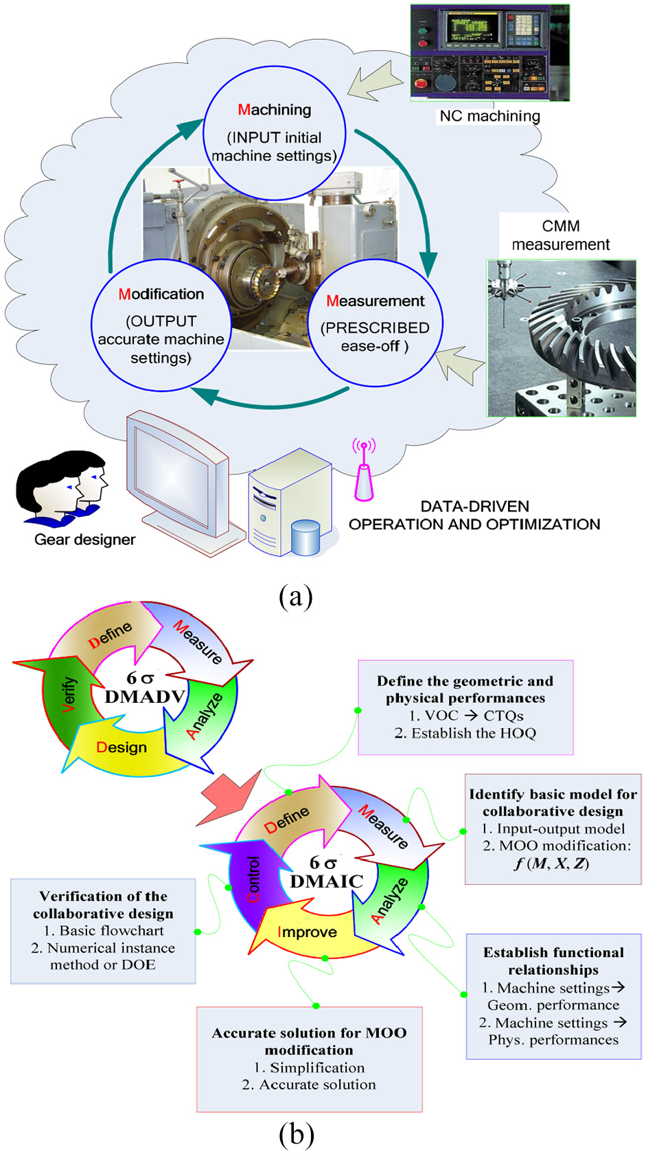
A novel framework for manufacturing process control: (a) manufacturing system and (b) DMAIC framework of DFSS.
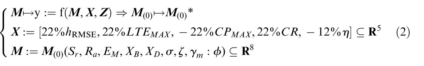
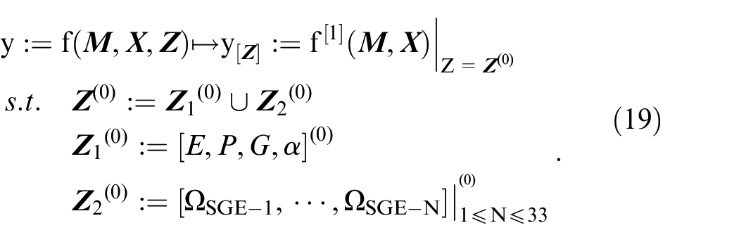
In its DFSS in Figure 1(b), define phase is important to the implementation of DFSS-based manufacturing process control. It aims at further modification and expansion of VOC. 40 HOQ is established to convert VOC into CTQs. Where, the accurate quantification of customer demands is used to get a product collaborative design and performance evaluations. 41 In measure phase, MOO hypoid generator setting modification f (M, X, Z) is used to firstly establish a basic input-output model for control system. The main objective of analyze phase is to establish functional relationships of hypoid generator settings with respect to geometric and loaded contact performance items. An accurate solution for MOO modification is described to determine the accurate hypoid generator settings as an output response in improve phase. If noise factors in manufacturing are also developed in the design, the identification will be difficult. Finally, numerical instance or DOE is employed to verify the proposed method.
Basic control flowchart
In this phase for DFSS, two schemes are provided to verify the proposed improve design: (i) numerical instance approach and (ii) DOE. With provided DFSS, the accurate hypoid generator settings are determined to execute the actual numerical control machining satisfying CTQs.42,43 Therefore, a manufacturing process control is performed for spiral bevel and hypoid gears considering both geometric and physical evaluations. Figure 2 shows the conceptual flowchart of DFSS-based manufacturing process control for spiral bevel and hypoid gears. To satisfy the customer needs with regard to gear product, an improved design considering geometric and contact performances is developed. Distinguished with DMADV framework of DFSS, an improved DMAIC framework is used to realize the decision and optimization for the proposed manufacturing control system.
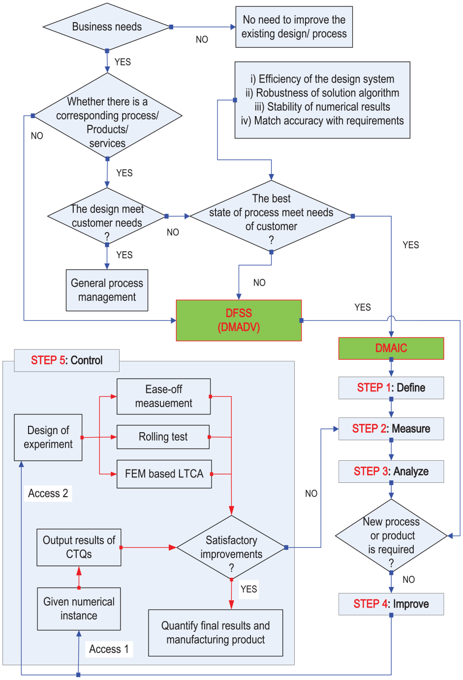
A basic flowchart for the DFSS-based manufacturing process control.
Since the existing design process, product or services can not satisfy the business needs although they are from a DFSS framework, an improved DMAIC framework needs to be performed by the proposed MOO hypoid generator setting modification. Where, the following evaluation strategies are provided when it needs to execute the DMAIC framework of DFSS.
Efficiency of the design system. The proposed MOO modification of hypoid generator settings is a complex system considering the noise factors and numerous input signals with mutual coupling. 20 The whole system involves the coordination of sub-objective optimization, data-driven programming and multi-variable functional relation expression and other data-driven operation methods.18,19
Robustness of the solution algorithm. In MOO problem, in addition to noise factors, stronger nonlinearity problem of the established modification model,14,15 the mutual coupling of sub-objective optimization 20 and convergence of the iteration step and other factors, are needed to be dealt with by using the achievement function approach.
Reliability of numerical results. Though numerical result is obtained, the singularity 44 and invalidity phenomena 20 affecting reliability still occur. For instance, with computation of the proposed modification, calculated hypoid generator settings with modification variation of 0.0001 mm was obtained, which was obviously insignificant in practice.
Matching with the given requirements. With the obtained numerical results, the reasonable evaluation strategy for the established requirements especially for some with strong correlation is required to match the prescribed performances. If match accuracy is low, the corresponding modification approach needs to be proposed by correlating with data-driven or numerical optimization, or other existing solution methods.
With accomplishment of the above phases in front of DFSS, the fifth phase in Figure 2 will be presented in detail in the following section.
DFSS-based manufacturing process control
Due to complex tooth flexural behavior and loaded contact performance requirements, manufacturing process control of the spiral bevel and hypoid gears always is a significant challenge. In this paper, beginning with the identification of geometric and physical evaluations, a DFSS-based operation and a robust design is given for the qualified product manufacturing control.
Determine CTQs by HOQ
Generally, facing with the massive, vague, uncertain, and even paradoxical VOC in market, QFD42,43 is usually used to transform it into important, accurate, and useful information. It can actually reflect the optimized screening, precision processing, and fuzzy optimization. The VOC from layer to layer is expanded to satisfy the requirements from product development and manufacturing, and to extract CTQs. Figure 3 shows the basic determination of high performance requirements for spiral bevel and hypoid gear product. In the optimal operation about CTQs, when tooth flank modeling is firstly performed to get an accurate solid model, TCA/NLTCA is used to establish data-driven relationships between the design variables and performance evaluations, and then the final performance evaluations are determined by using the QFD. Here, with the synthesis and analysis, 43 the main performance evaluation items on tooth flank geometric and loaded contact performances were selected as: (i) Minimization of hRSME18,19; (ii) Minimization of CPMAX21,22; (iii) Minimization of LTEMAX22,23; (iv) Maximization of CR19,22; and (v) Maximization of η.21,44 The above five requirements can be generally classified into geometric performance including the item (i) and loaded contact performance including items (ii), (iii), (iv), and (v). A simplified HOQ45,46 according to the identified optimal CTQs has provided for spiral bevel and hypoid gears in Chen et al. 47 and Shao et al. 48
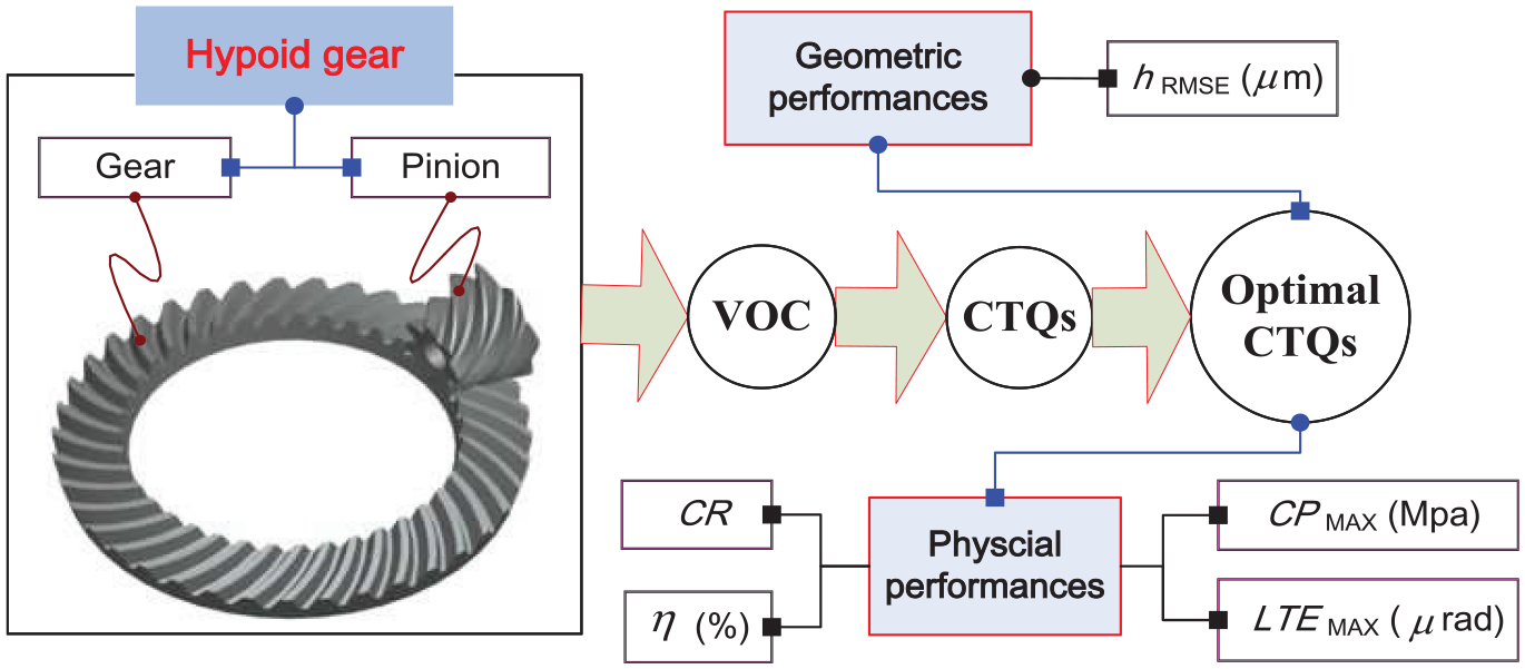
Determination of the high performance requirements for spiral bevel and hypoid gear product.
The data-driven relation between VOC and CTQs, as well as the close and complex relations between CTQs are also illustrated in HOQ. With the implementation of HOQ, 49 the customer needs, research objective and design goals for spiral bevel and hypoid gear are classified and identified. Here, to satisfy the selected geometric and physical evaluations, the final CTQs can be transformed into MOO function with regard to design factors
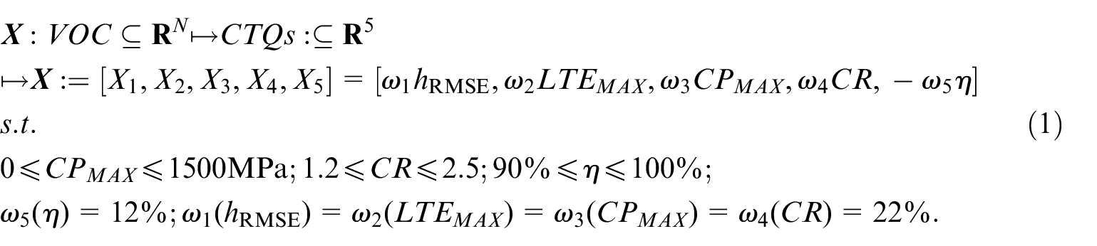
importance weights of the selected design factors can be determined by using comprehensive evaluations of CTQs. The detailed transformation by using QFD can refer to Raharjo et al. 42 and Cristiano et al. 43
Basic model
Hypoid generator setting modification has become an important access to MOO considering gear product CTQs.19,21 Next, the primary task is to determine the data-driven relations between the loaded contact performance evaluation items and design variables namely hypoid generator settings. Here, in consideration of VOC and CTQ in market, a MOO hypoid generator setting modification is employed for high-performance gear product manufacturing. Here, the basic model of manufacturing process control as an input-output model
For representing eight basic universal hypoid generator settings in UMC framework,
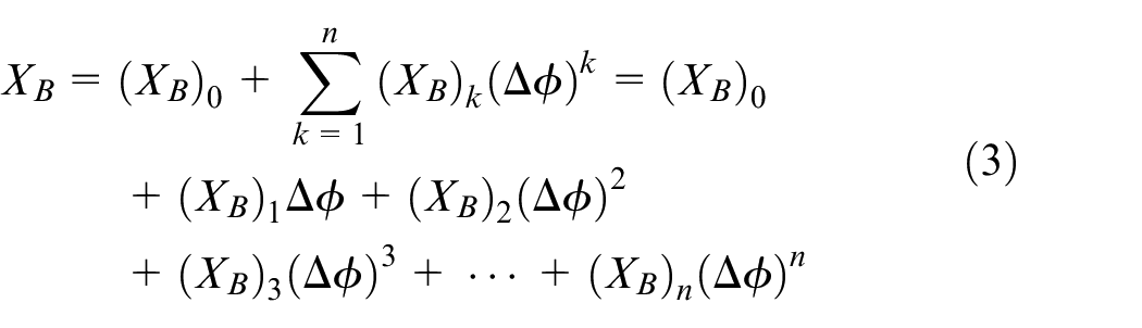
Apart from XB, they also include other hypoid generator settings, such as XD, ζ, σ, Ra, EM, and γm. With the application of universal hypoid generator settings, an accurate tooth flank is generally modeled by simulating the actual generation process of the cutter blades with gear blank. The machine kinematics satisfying well-known theory of gearing as
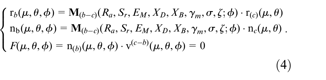
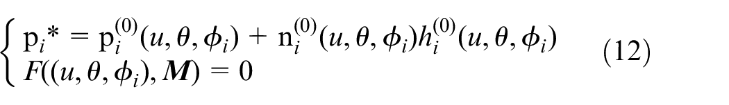
Tooth flank is constructed by a collection of the corresponding discrete points and F(µ, θ, ϕ) = 0 is the well-known gear equation of gearing.12,13 Where,
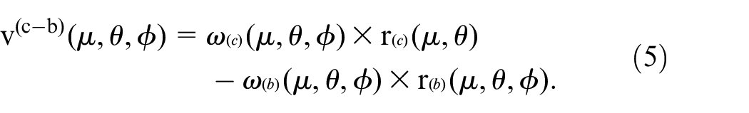
In the improve phase of the proposed DFSS, a set of universal hypoid generator settings
In consideration here of

The detailed computation process can refer to Artoni et al.
23
As indicated in equation (6) and Figure 4, the assembly error generally includes four evaluation items, namely
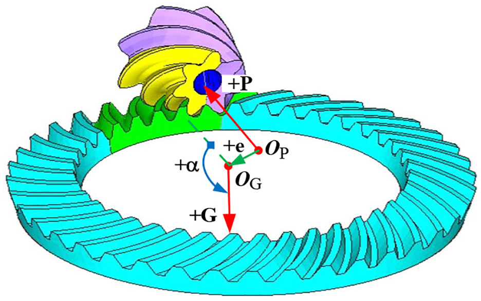
Basic setup of the assembly error evaluation items for spiral bevel and hypoid gears.
The relations of SGE with respect to hypoid generator settings in modification have been developed in Ding et al. 20 There are totally 33 evaluation items and their function is represented as

The detailed solution about SGEs can refer to Artoni et al. 23 Their definitions and descriptions are omitted for brief here.
NLTCA by using shell theory and Rayleigh-Ritz method
Now, double-curved shell theory is applied to establish an accurate finite element model satisfying the tooth flexural characteristics of spiral bevel and hypoid gears. Then, NLTCA is used to determine data-driven relationships between loaded contact performance evaluations between the hypoid generator settings. The direct data-driven relation establishment can improve the accuracy and efficiency of the proposed control strategy.
Finite element model
Recently, NLTCA is sparsely developed for the spiral bevel and hypoid gears because of its complex tooth flexural behavior characteristics. Moreover, as for the spiral bevel and hypoid gears, the beam or plate finite element is mainly applied for NLTCA solution. With regard to shell element in Figure 5, as for the face-hobbing or face-milling hypoid gear in full consideration of the flexural behavior, a double-curved shell with varying thickness is more representative to represent finite element geometric shape than a beam or plate model. The detailed modeling can refer to Ding et al. 56
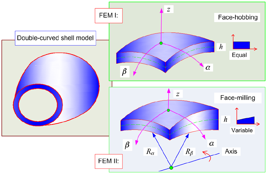
A double-curved shell model considering tooth flank flexural behavior.
Determination of tooth stiffness
In recent determination of tooth stiffness for spiral bevel and hypoid gears, an important numerical solution is a semi-analytical approach by applying shell theory and Rayleigh-Ritz method. 29 In particular, Ding et al. 56 established a double shell finite element model for face-milling spiral bevel and hypoid gears and determined the tooth stiffness by using Rayleigh-Ritz method. In this work, this method is also employed for stiffness determination. The transverse deflection W and βx and βθG, are determined by considering the first variation of the potential energy to zero in Rayleigh-Ritz method. QPE for a conservative system is the difference between QSE and QWF. It assumes that QPE = QSE−QWF, thus it can obtain as
NLTCA equations
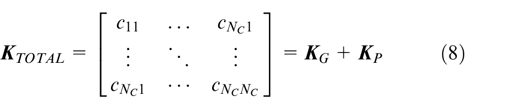
When tooth flank in total contact pattern area is divided into NC segments, each segment has its own local load and the loaded contact deflection. Thus, tooth stiffness of pinion and gear are determined by equation (10),
In the finite element model, the potential contact curves are calculated and discretized into NC, and their length and separation are primary input for determining the NLTCA evaluation items.
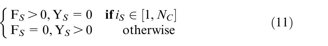
To obtain NLTCA equation set, it is needed to satisfy simultaneously the following conditions 58


Equation (9) represents the compatibility condition. 58 Moreover, equation (10) represents the equilibrium condition. 58 Finally, the following condition is provided for judgment of the loaded contact as
Here,
Improved data-driven operation and optimization
While DFSS in integrated with NLTCA, an accurate MOO hypoid generator setting modification can be sued to ensure the accuracy and efficiency of the whole process control. In DFSS-NLTCA based manufacturing process control, there are all kinds of noise factors17,20 such as heat treatment distortions, machine tolerances and variation of cutting forces which can cause geometric performance deviation between the theoretical and the real tooth flanks. Therefore, function relationships between noise factors and hypoid generator settings are needed to be established to implement the MOO modification.
Functional relations for MOO modification
Functional relations between hypoid generator settings and the geometric performance are of great significance to the whole process control.17,19 It is evident that the accurate modification can be only if the accurate tooth flanks such as basic flank, target flank and current flank are established. The basic flank with m data points
Where, any modification of tooth flank geometry with respect to basic design flank is called ease-off hereafter.14,15 The ease-off topography can be fitted by sampling these ease-off points. As evaluation standard of approximation degree for a target flank, i-th component hi(0)∈
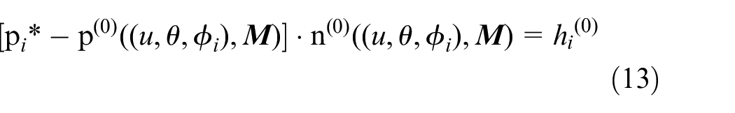
here, high-order ease-off modification can be translated into a minimization optimization problem26,36,50 and its modification model is represented as
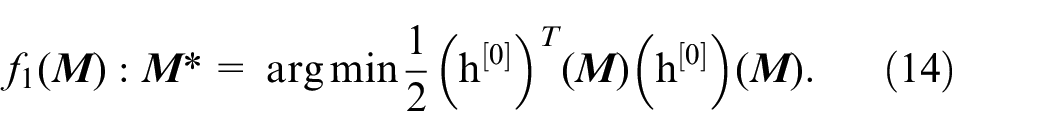
With the proposed NLTCA method in DFSS-based manufacturing system, data-driven functional relationship of loaded contact performance evacuations with respect to the hypoid generator settings can be represented as

where, fi(
However, with regard to η, it can be computed from TG and ωG as 44
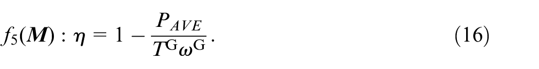
There are the following relations 44

Optimal data-driven operation to noise factors
After establishing data-driven functional relationships of geometric and loaded contact performance evaluations, MOO function set is established, as well as the DFSS-based framework of manufacturing process control. Next, the whole system will be data-driven optimization by using hypoid generator settings are proposed, as well as data-driven operation and optimization methods. First, assembly error is considered as a main noise factor in this work. In eTCA, assembly error is sensitive to tooth performance evaluation items. Thus, assembly error is recognized as the vital noise factor in the actual spiral bevel and hypoid gears manufacturing. In addition, assembly error can be directly integrated into hypoid generator setting modification by the prescribed ease-off topography. Moreover, SGEs of machine spindles in the actual machining will also be taken into account in this study as a main machining error items. It is reported that 20 the SGE can be divided into two categories, linear error and rotational error, which includes 21 kinds and 12 kinds of error items, respectively. Here, the LDDM laser measurement system of Doppler laser interferometer MCV2002 according to ISO 230-2(1997) standard 52 is adopted to make measurement of the three linear shafts. Doppler laser interferometer MCV2002 with an RT-100 rotator in Figure 6 is used to make measurement of two rational spindles. Then, the software error compensation method with the NC data 53 is further exploited for the SGEs compensation. It is worth noting that there are many SGEs from the five-axis hypoid generator and they have obvious effects on the tooth flank topography and performance evaluations,54,55 especially for the actual tooth flank manufacturing geometric accuracy. The detailed measurement and compensation method can refer to the basic methods in Ding et al. 20
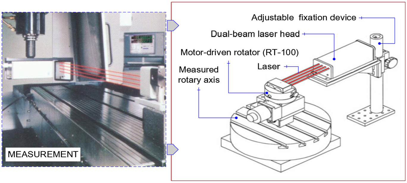
Rotary angle measurement with Doppler laser interferometer MCV2002+RT100.
MOO modification solution
Intrinsically, the proposed methodology in this work belongs to a tooth flank topography optimization problem and it can be transformed into a MOO hypoid generator setting modification. 22 To achieve efficient control, 57 a smart computation is applied to solve the simplified MOO objective function for the robust hypoid generator settings with modification amounts.
Simplification of the MOO function
First of all, to get a data-driven MOO function with respect to hypoid generator settings, the influences of noise factors such as assembly error and SGE are needed to be considered here. With the aforementioned optimal operation, MOO modification can be simplified as
where ΩSGE-N (N∈[1,33]) can be compensated by using numerical control technique. It was reported that influence of noise factors can be removed before hypoid generator setting modification, and a new tooth flank was provided to numerically compensate it in the proposed design. 58 And then, with establishment of relationships of the hypoid generator settings with CTQ items, the design can be further simplified as
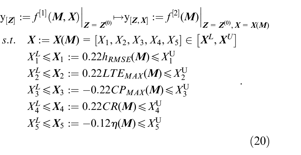
Finally, by considering the established the constrain conditions, a constrained MOO problem can be represented as
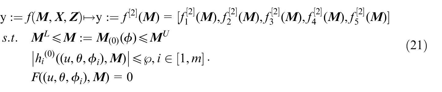
Since the above five objective functions may be conflicting in general, equation (21) has not a unique optimal solution, and an improving of one objective may result in performance degradation of another objective. Thus, a compromise solution has to be selected according to some measure of preference of a solution over another. 21 Here, some basic concepts in MOO field are firstly introduced.
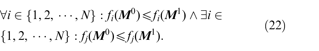
Definition 1: Pareto dominance. For two given points
Definition 2: Pareto optimal set. The solution

All of Pareto optimal solutions constitute the Pareto optimal set

Definition 3: Pareto optimal front. The feasible region
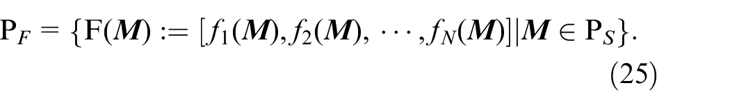
Such Pareto optimal set contains all of the compromise solutions and provides a basis for determining the final solution. Therefore, with the established functional relationships, the MOO modification needs to get a smart solution by searching from the Pareto optimal set.
MOO robust solution
In order to get a robust solution, a classical achievement function method is used to solve the MOO problem as
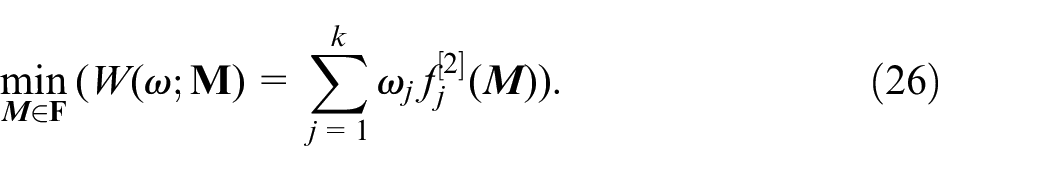
where
All objective functions and their values fj[2](
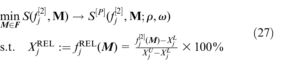
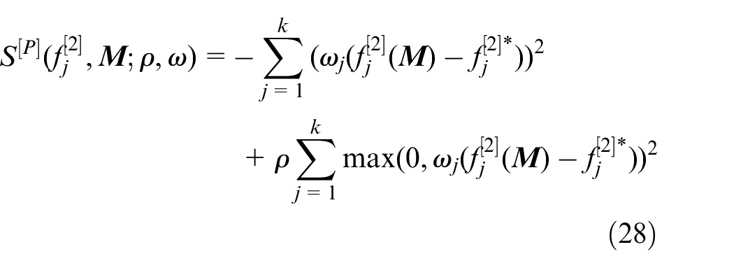
here, ρ > 1. Wierzbicki 60 provided the detailed expression of S[P] and the MOO problem is finally
All maximum of S (F→R) correspond to Pareto optimal solutions
It is worth notation that the above achievement function approach belongs to an interactive reference point method. After determining the Pareto optimal solution corresponding to the specified reference point, the calculation process of interactive step is to be performed by determining the Pareto front

The basic flowchart of MOO computation.
Numerical instance
Basic gear design
In numerical instance, a set of hypoid generator settings of the real face-milled spiral bevel and hypoid gears61,62 is selected as the basic input signal to DFSS. The accurate hypoid generator settings are determined as a data-driven output response for the actual numerical control manufacturing. With the basic design process of DFSS-based manufacturing process control strategy, the pinion of a real Gleason spiral bevel and hypoid gear drive for automotive application63–65 which is processed by HFT modification summary is the main optimization object of this research.
66
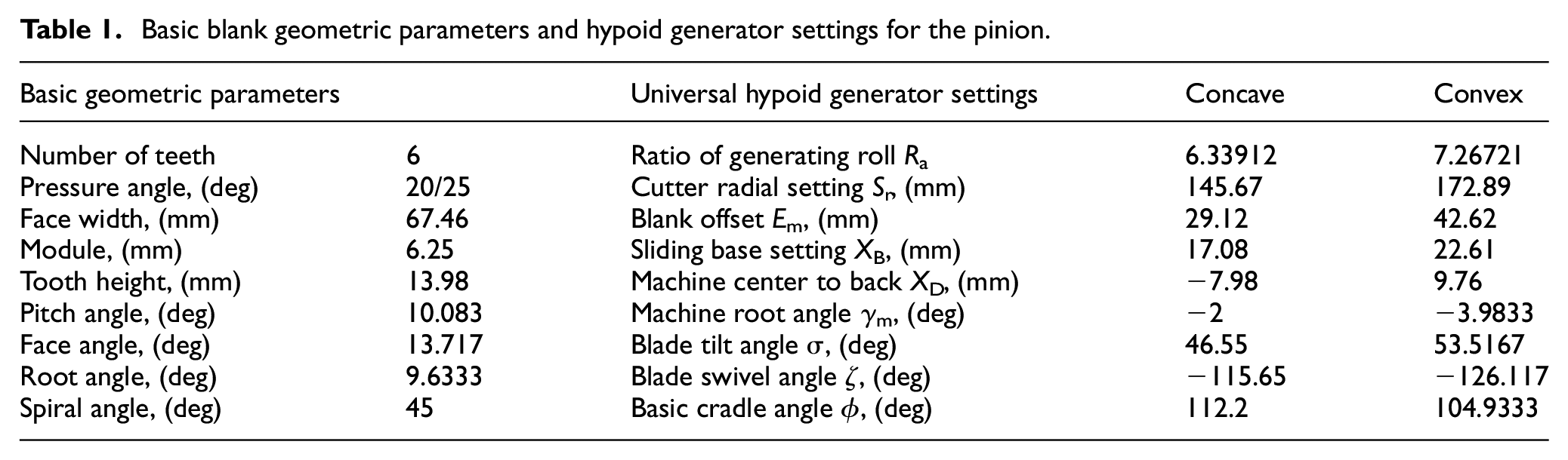
In the actual machining for the pinion by the Tilt® approach, the process platform is hypoid generator YK2050. It is a very common and typical platform in recent Five-cut process. Table 1 shows the basic blank geometric parameters and hypoid generator settings
Basic blank geometric parameters and hypoid generator settings for the pinion.
Noise factor operation
With the proposed DFSS methodology, the influence of noise factors with hypoid generator setting modification can be identified and controlled within the appropriate range. For instance, for a work spindle of hypoid generator, there are numerous spatial geometric errors. Figure 8 shows the influence of the assembly error on geometric and physical evaluations. Where, hRMSE is used to represents geometric performance evaluation and LTEMAX represents loaded contact performance evaluation where this setup can refer to the Ding et al. 20 and Shao et al. 48 The results can indicate that assembly error can affect the geometric and loaded contact performances.
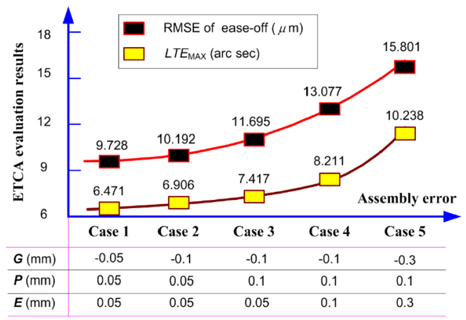
Influence of assembly error on the tooth contact performances.
Figure 9 shows an accurate measurement for SGEs of five-axis linkage CNC hypoid generator YK20250 by applying the Doppler laser interferometer MCV2002 with an RT-100 rotator. It is worth notation in full consideration of complex machine structure and miscellaneous SGEs evaluation items, the cutter axis A-axis is selected to get an accurate measurement of its SGEs. Actually, the final target is to get an accurate gear product manufacturing and the tooth flank manufacturing geometric accuracy is paramount task under the accurate measurement and compensation of all kinds of manufacturing noise factors. 69 Figure 10 shows the measurement values of the horizontal straightness, vertical straightness and swivel angle. These results are then submitted into NC system to obtain compensations in the actual machining based on YK2050 hypoid generator.
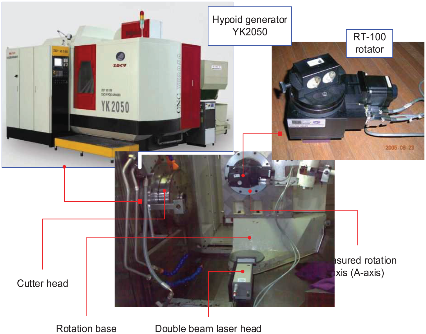
Accurate measurement for SGEs of the five-axis linkage CNC hypoid generator YK20250.
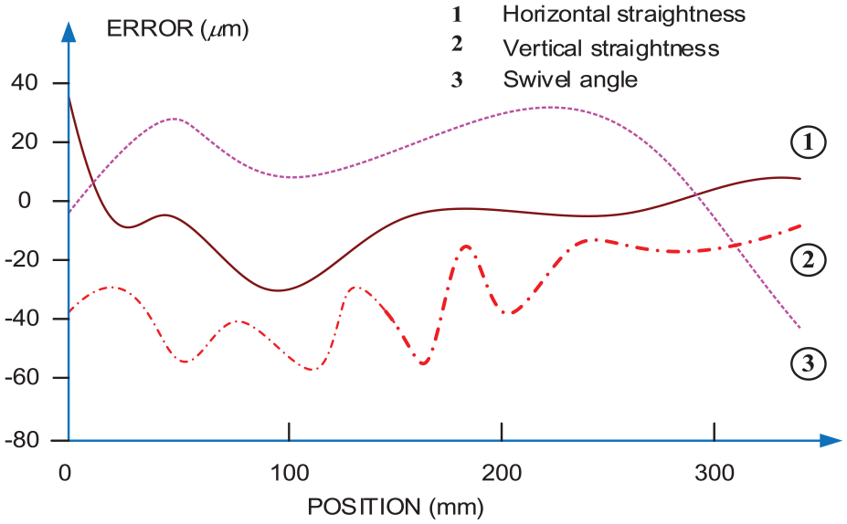
Some spatial geometric errors of the hypoid generator by measurement.
Then, NLTCA is employed to obtain the data-driven relations between hypoid generator settings and loaded contact performance evaluations. Additionally, an improved hypoid generator setting modification model is selected to establish the relations with respect to the geometric performances. After operation of noise factors, the MOO modification is a key to basic DFSS-NLTCA process control. According to the prescribed requirements from the actual gear product manufacturing, Figure 11 represents the prescribed ease-off topography. Where, RMSE of ease-off is 32.763 µm while the maximum value is 53.23 µm and the minimum is −34.672 µm. The larger error lies tooth tip part around two end corners.
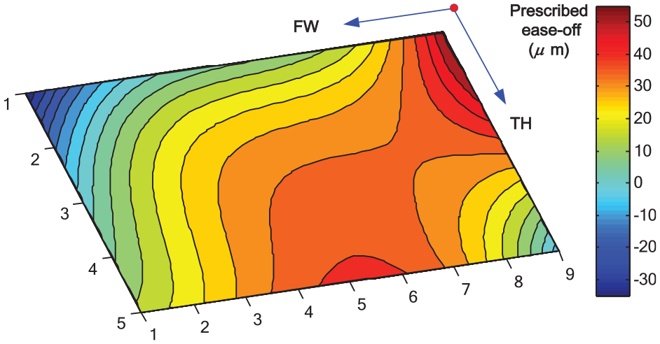
The prescribed ease-off topography.
MOO modification
In consideration of the prescribed ease-off which is a main geometric accuracy, MOO modification is performed by correlating with the proposed reference point approach. Figure 12 represents MOO iteration solution form data-driven manufacturing process control strategy considering five gear product performance evaluation items. It is worth noting that Pareto optimal solution
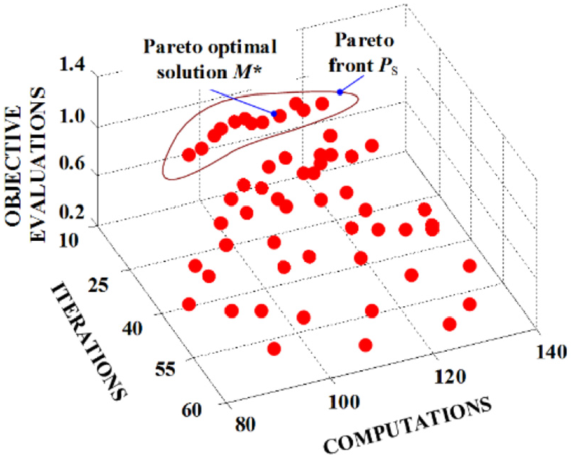
MOO iteration solution for the proposed data-driven manufacturing process control strategy.
Figure 13 shows their numerical results from the proposed DFSS-NLTCA process control. With the robust computation, the MOO result reflecting the tooth flank geometric and loaded contact performances relating to CTQs in DFSS are determined, respectively. Here, direction, size, and location of tooth contact pattern are in good agreement with the regulations in actual production.68,69CPMAX is 1013.26 MPa which is lower 32.45% then the maximum allowable value. As for transmission error which is main source of noise and vibration in gear transmission, LTEMAX is 45.314 µrad and reduced by 9.37% of the maximum allowable. With above calculations, CR is 1.635 and increased 36.52 by from the minimum allowable value, and η is 95.28 and increased by 5.78% from allowable value 90%. In particular, by referring to the general tooth flank geometric performance evaluation in Ding and Tang 71 and Peng et al., 72 the gear product geometric performance hRMSE is 0.0132 µm while the maximum value is 0.0251 µm and the minimum is 0.0026 µm. And the larger error is lies in the diagonal region and the small error is in tooth middle area. With MOO modification in the proposed manufacturing process control strategy, 70 the accurate hypoid generator settings with modification variations are obtained as the basic output from proposed DFSS-NLTCA process control. If it is qualified, the obtained accurate hypoid generator settings in this work can be output as the response for high performance spiral bevel and hypoid gear design and manufacturing.71,72
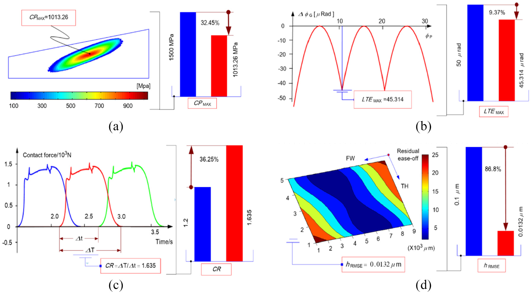
Results on the performances after MOO modification: (a) CPMAX, (b) LTEMAX, (c) CR, and (d) hRMSE.
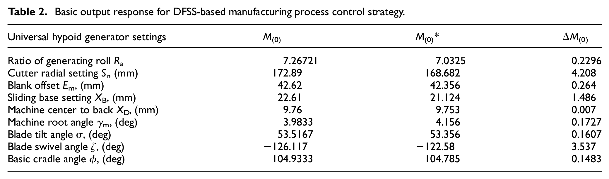
Table 2 represents a basic response for the data-driven manufacturing process control strategy. Where, there are Sr, XD, and ζ have obvious sensitivity and lager modification variations. It means that accurate hypoid generator settings can be provided for hypoid generator to execute the actual machining and obtain the hypoid gear product requiring the qualified geometric and physical evaluations.69,72 With the above numerical instance, a product improvement design is finally developed by using a basic DFSS-NLTCA control strategy.
Basic output response for DFSS-based manufacturing process control strategy.
Conclusions and future work
In this work, an innovative data-driven DFSS-NLTCA process control for manufacturing of spiral bevel and hypoid gears. Some distinct features of the proposed method are summarized as follows:
It is an innovative attempt to introduce DFSS into the manufacturing process of spiral bevel and hypoid gears. A DMAIC framework was selected to establish manufacturing process control model by correlating with hypoid generator setting modification technique. This DFSS method could play an important role in improvement of the competitiveness for hypoid gear product development or manufacturing. 69
In DFSS-based strategy, HOQ was established to convert VOC into CTQs and the final geometric and loaded contact performance requirements. Considering the collaborative optimization for gear product performances, a basic DFFS-NLTCA framework was established by using the MOO modification 67 including the input signal, output response, design factors, and noise factors. Furthermore, the modification was transformed into a MOO problem, which could enhance the efficiency of the whole control process, as well as improve its accuracy and robustness.
To distinguish with the conventional SLTCA method, 70 the innovative NLTCA is proposed to get the direct data-driven operation and optimization relating to the control accuracy and efficiency. It is a new attempt to get a collaborative manufacturing 72 for multiple loaded tooth contact performances directly affecting the noise and strength. This data-driven design based on the hypoid generator settings can get an important access to the collaborative optimization between the theoretical design and the actual manufacturing of spiral bevel and hypoid gears in consideration of high performance requirements.
In MOO modification, measurement and NC compensation were applied for optimal operation of the given noise factors, which made the proposed methodology get a more significance to the actual manufacturing. 69 Moreover, considering numerical stability problem, the obtained MOO problem was solved by an interactive reference point method and the accurate hypoid generator settings with modification variations were obtained as the basic response. With the above optimization and operations, the DFSS-NLTCA control could be of a good validity and might serve as an expert system for the manufacturing process control strategy of high-performance spiral bevel and hypoid gears.
The systematic nature of the proposed DFSS make it possible to develop high-efficiency manufacturing facing with customer requirements, there are still some work need to be done in the future works. First, how to accurate define every phases in DFFS. A rough description was offered on this work and more details could be dug. For instance, in the QFD for converting VOC into CTQs, the inherent vagueness or impreciseness problem, which is simplified in this work, is very complex. Second, how to validate the proposed methodology by DOE in the verify phase of DFSS. The actual experiments should be of more convincing to demonstrate the designed performance of the designed spiral bevel and hypoid gears. Third, more complex human-machine interaction behaviors in actual machining need to be integrated into the DFSS, which would make the robust data-driven control more difficult. However, when there is a general computational intelligence aided design is applied for the above process control system, it will provide a very desirable basis for the future intelligent manufacturing.
Footnotes
Appendix
Declaration of conflicting interests
The author(s) declared no potential conflicts of interest with respect to the research, authorship, and/or publication of this article.
Funding
The author(s) disclosed receipt of the following financial support for the research, authorship, and/or publication of this article: The authors gratefully acknowledge the support of the National Natural Science Foundation of Hunan province through Grants No.2020JJ4115, Fundamental Research Funds for Central Universities, Central South University, through Grants No.2020ZZTS488, Hunan Postgraduate Scientific Research Innovation Project through Grants No.CX20200186 and National Natural Science Foundation of China (NSFC) through Grants No.51535012, 51665056, U1604255.