
Abstract
Error compensation technique is a recognized and cost-effective method to improve machining accuracy of machine tools. In this article, a new compensation method for geometric error is proposed based on Floyd algorithm and product of exponential screw theory. Based on topological structure and measured data, volumetric geometric error modeling is established by product of exponential screw theory. Then, the improved Floyd minimum-distance method was used to establish an error compensation model by adjusting weight unceasingly. In order to verify the effectiveness and generality of the method proposed in this article, two experiments were designed. A total of 5 five-axis machining centers of the same type with different use time were selected to carry out the simulation experiments. Results show that the Floyd method can provide higher compensation precision, that is, Floyd algorithm compensation method can keep positioning errors within the range [−8 µm, 9 µm]. In addition, roundness error, coaxial error, and surface roughness were reduced in the actual machining experiments of two machined conical tables. Therefore, it can be seen that the proposed compensation method is effective to improve machining accuracy of machine tools.
Introduction
Accuracy is a key parameter used to evaluate machine tool characteristics and performance.1–3 Accuracy of a machine tool is influenced by many factors. Among them, geometric errors account for about 40% of total machining errors. 4 According to the characteristics of geometric errors, compensation of such errors has proven to be an effective way to improve the machining accuracy. Geometric errors of the machine tool typically exist in all mechanical parts. This error propagates into machining error of the workpiece. In addition, errors induced due to precision of parts and assembly technology significantly influence accuracy, particularly in high precision machine tools.
At present, error compensation technology is a primary method used to improve machining accuracy of the machine tool. In the past, errors were minimized by improving precision of parts and machine tool assembly during mechanical design and manufacturing. 5 This was achieved by improvements in geometry, surface quality, and mutual position of the machine tool component parts. However, practical implementation is restricted due to limitations associated with physical enhancement of machining accuracy, which is associated with the maximum limit being reached by state-of-the-art machine tool design techniques. Further improvements in machining accuracy can be achieved; however, this would result in a dramatic increase in costs. 6 Therefore, studies on error compensation technology become increasingly attractive for improving machine tool accuracy. 7
Volumetric error model
Over the past several decades, research has been focused on modeling of machine tool errors along with geometric error. Research has been especially focused on investigating the influence of geometric errors on three-axis machine tools. 8 A wide array of modeling methods for geometric errors have been proposed from different perspectives, including Denavit–Hartenberg (D-H) method,9–13 geometric modeling method, error matrix method (EMM), quadratic model method, mechanism modeling method, rigid body kinematics method,14,15 and multi-body system (MBS) kinematics theory. 16 Lin and Shen 17 proposed a matrix summation approach, which divided global geometric errors into six components. This approach made the model manageable and improved understanding due to the clear link to physical parameters. Fan et al. 18 proposed a kinematic model based on MBS theory by adding movement and positioning error terms. This approach allowed the development of a generalized kinematic model, which was applicable to numerical control (NC) machine tools. Bohez et al. 19 fit error components using cubic polynomials to establish a first-order mathematical model. They also proposed a corresponding solution method for error compensation. Chen et al. 20 developed a volumetric error model for machine tools in accordance with rigid body kinematics and homogeneous transformation matrices. Furthermore, they performed sensitivity analysis for all error components used in machine design. Kiridena et al. 21 mapped the effects of positioning errors on volumetric accuracy for a five-axis computer numerical control (CNC) machine tools. Wang 22 and Shen et al. 23 proposed a laser vector or sequential step diagonal measurement technique to determine volumetric positioning errors. This was achieved by modification of the body diagonal displacement test method in ISO230-6. 24
In recent years, screw theory, as a basic method, has been widely used to describe pathways in robotics, which can be used to develop a model clearly expressing the kinematic chain. This can be achieved because the model effectively describes the motion of robots according to geometric property, and it is a zero reference position method. 25 Moon et al. 26 studied geometric error modeling and compensation applied to machine tools using the screw theory. They expressed basic error components of each joint as a modular error screw. Moreover, modular error screws and motion screws of the joints were defined with respect to a global reference frame. This method was used to establish a three-axis machine tool model without rotation axis. Fu et al. 8 proposed a product of exponential (POE) model to integrate geometric errors in multi-axis machine tools. This model expressed geometric meaning of basic errors successfully. Accuracy of geometric error model was greatly improved by application of screw theory. Thus, screw theory can be considered as one of the best methods for geometric error modeling.
It is important that the model be based on experimental measurements in order to build an accurate geometric error model. To overcome the need for experimental measurements, a volumetric geometric error model needs to be established. In this article, PoE screw theory is used to carry out this work.8,26,27
Error compensation
Error compensation technique focuses on counteracting major errors during machining. 28 In error modeling, a relationship between predicted machine errors and position coordinates is established. Next, compensation data are sent to a CNC system. Error compensation is implemented using internal compensation functions or external compensation software. A typical internal compensation function is lead-screw compensation implemented in CNC systems. External software compensation is an effective way to eliminate the machining error at low cost and has been the focus on considerable attention in the manufacturing industry. 29
In the past decades, there have been numerous research reports focused on the geometric error compensation methods. Jing et al. 30 experimentally demonstrated that machining error could be significantly reduced by corrections to the NC program. In general, error compensation can broadly be divided into two categories: (1) real-time compensation achieved by communication to the CNC controller through digital I/O interface 31 and (2) pre-compensation, which can be achieved by modifying tool path (NC codes) in post-processing.9,13,29,32,33 However, none of the above methods have demonstrated an efficient geometric error compensation. In addition, compensation methods are different for three-axis and five-axis machining. In three-axis machining, compensation procedure is not dependent on the geometrical model of the machine. In the case of five-axis machining, generally two rotary axes are active; as a result, both tool orientation and position need to be modified. 32 In the previous work, we presented a systematic method for error compensation in three-axis machining. However, the proposed method was found to be inefficient, when applied to five-axis machining.
In this article, a new geometric error compensation method for machine tools based on Floyd algorithm is proposed. First, error modeling procedure based on PoE screw theory is introduced. Next, a volumetric comprehensive error model for a five-axis machine tool is established based on the topological structure. This is followed by a presentation of a new error compensation method based on the Floyd algorithm, which uses path adjustment and weight unceasing to achieve error compensation. A total of 5 five-axis machining centers were selected to carry out numerical simulation experiments to verify the effectiveness and generality of the Floyd algorithm. In addition, two workpieces were machined to verify the effectiveness of the compensation method in practical applications. Finally, a summary of research finding is presented along with discussion on a proposed compensation model for higher compensation precision. Figure 1 summarizes the framework of this research.
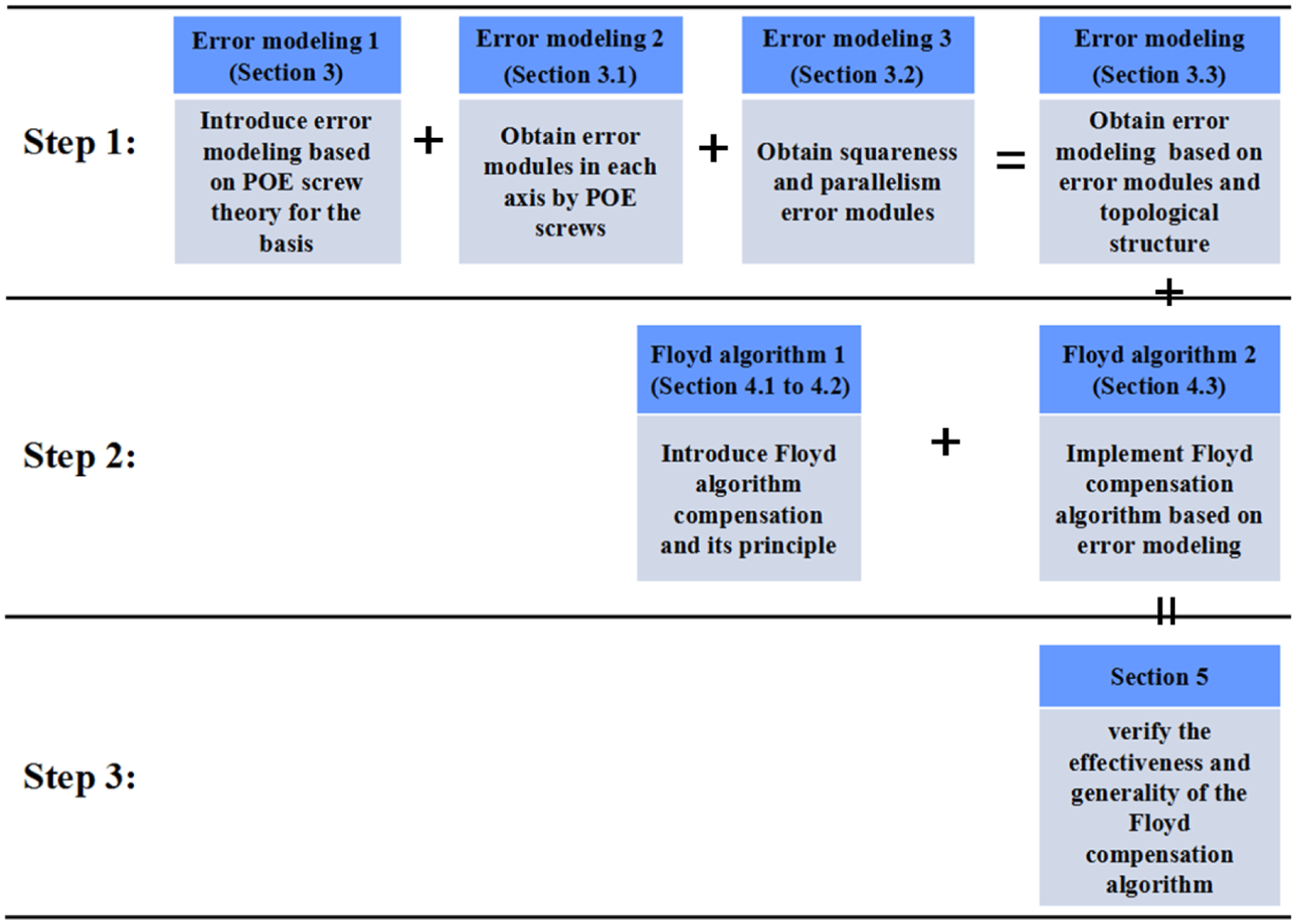
Framework of the proposed approach.
Screw theory and PoE model
In this research, error modeling was based on screw theory. Consider an ordered pair whose previous and next vectors do not satisfy orthogonality conditions. Thus,
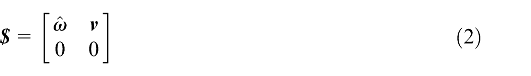
Any motion of a rigid body in three dimensions can be considered as the sum of a rotation about an axis (i.e. screw axis) and translation along that axis.8,9 A screw can be regarded as a general motion of rigid body along one axis. 34 During instantaneous motion, the screw is expressed as follows
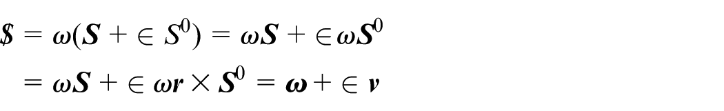
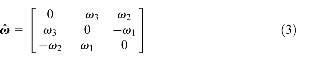
where ω denotes the instantaneous angular velocity,

Assume that
where
As stated earlier, composite motion of a rigid body can be described as the sum of the rotation and translation. 35 Assuming that the vector between the rigid body coordinate system and reference coordinate system is q, the homogeneous transformation matrix of the rigid body is given by
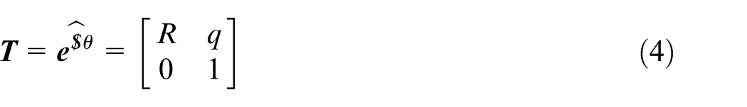
Exponential matrix of the screw is also the corresponding homogeneous transformation matrix,
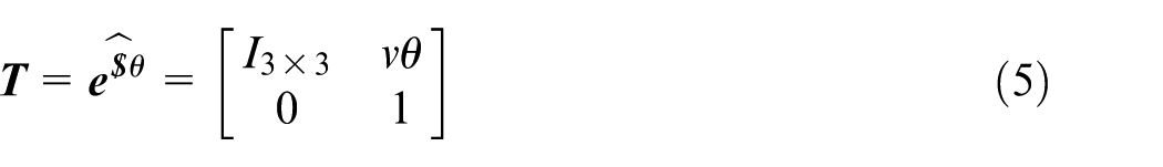
If
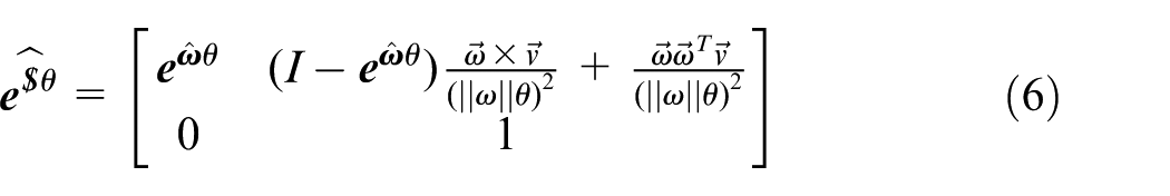
Expanding
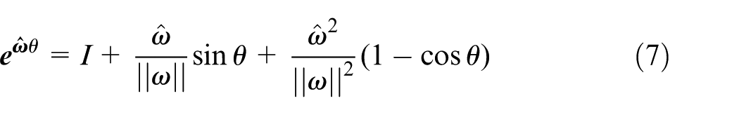
In all of the above-mentioned equations, if the screw
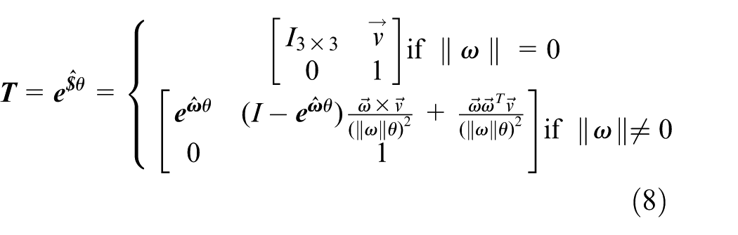
When
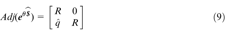
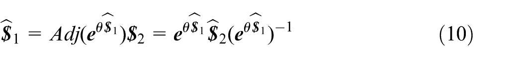
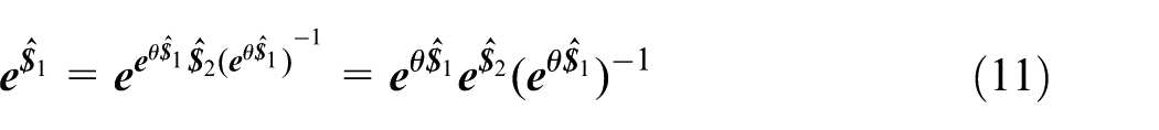
Equations (10) and (11) describe adjoint matrix properties 38
Moreover, PoE screw theory modeling expresses forward kinematics of an open chain mechanism. For an n-degrees-of-freedom (DOFs) mechanism, forward kinematics can be written as follows 8
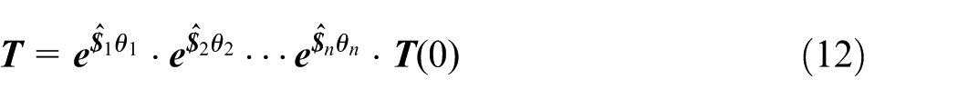
where
Five-axis machine tool error model
Here, a five-axis machine tool was used as the subject of error modeling. A schematic diagram of the five-axis machine tool is shown in Figure 2.
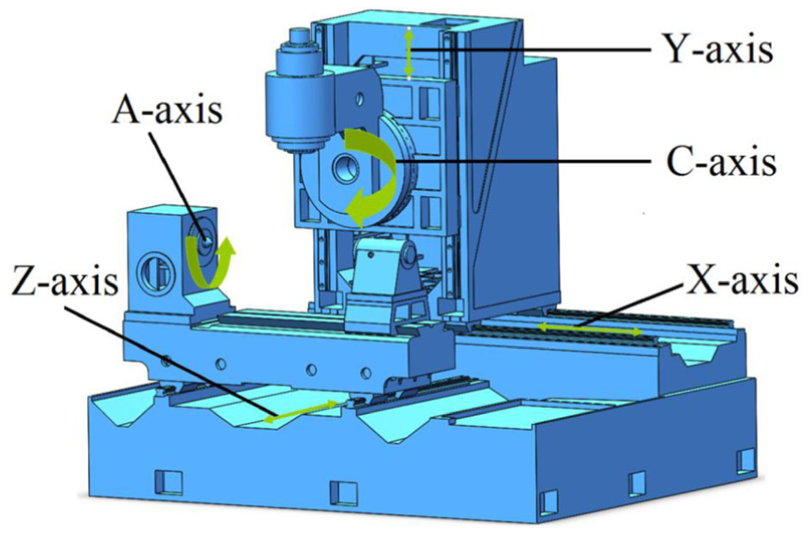
Schematic diagram of a five-axis machine tool.
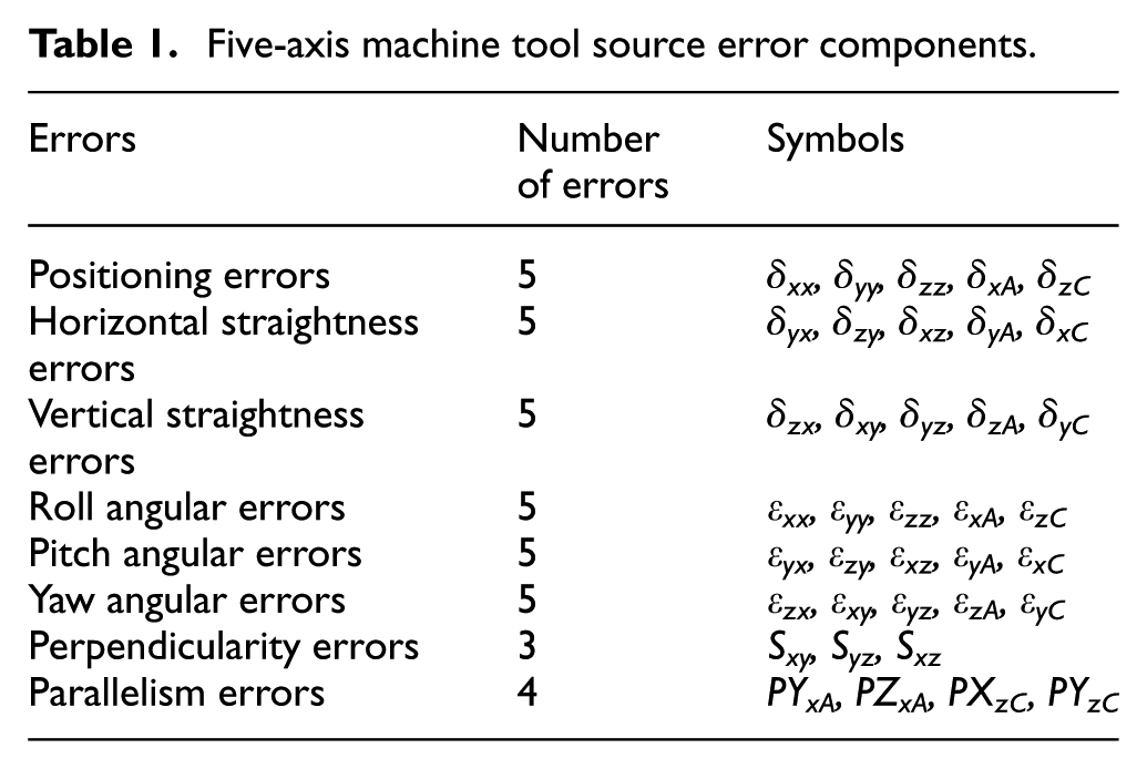
Table 1 lists the 37 sources of error in the five-axis machine tool. Perpendicularity and parallelism error axes were measured using a geometric error measurement instrument, as shown in Figure 3. In addition to perpendicularity and parallelism errors, other geometric errors were directly measured with a dual-frequency laser interferometer, as shown in Figure 4.
Five-axis machine tool source error components.
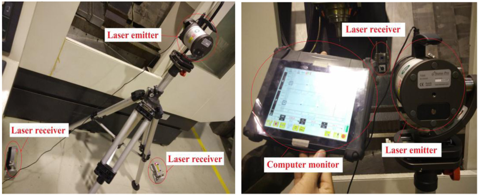
Measurement of perpendicularity and parallelism errors.
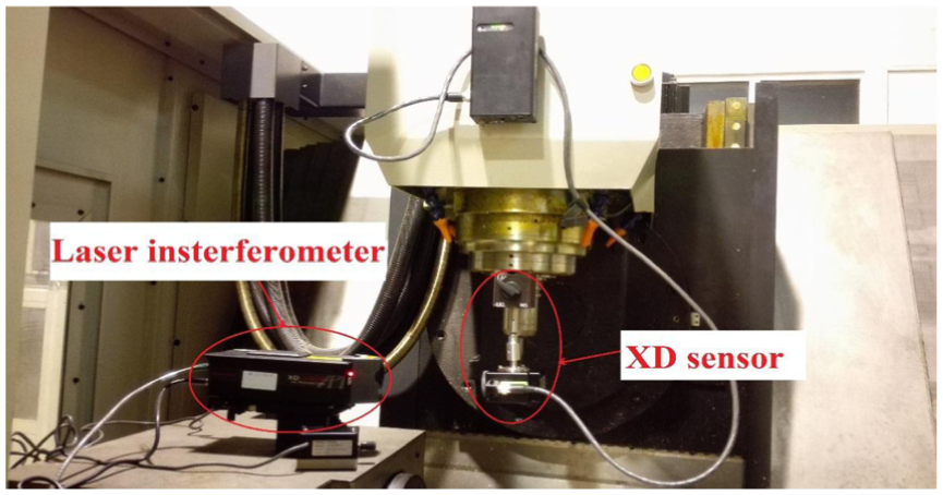
Measurement of 30 geometric errors with laser interferometer.
Linear and angular errors are denoted by δ and ε, respectively. For example, δyx is the linear error in y-direction with motion along the X-axis. As shown in Figure 5, first subscript refers to direction of error and the second refers to direction of movement, namely, the linear axis. Similarly, for εij, first subscript refers to rotation axis of angular error and the second refers to direction of movement. Here, errors are expressed as screws, and error modeling can be established by PoE.
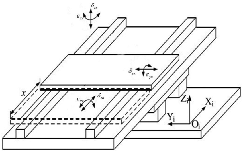
Six error components of the X-axis.
Due to manufacturing and installation defects, each axis has geometric errors. These errors can be described by six error components: three translational and three rotational components (one for each DOF of the rigid body). Therefore, according to screw theory, they can be defined as modular error components

Taking the X-axis component as an example, the first group contains linear positioning error
Geometric error model for each axis
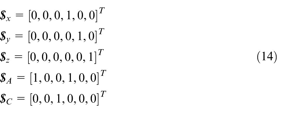
A five-axis machine tool has three translational motions (along X-, Y-, and Z-axes) and two rotations (about A- and C-axes). Thus, unit motion screw is as follows

where vector
The exponential matrix of a five-axis machine tool motion
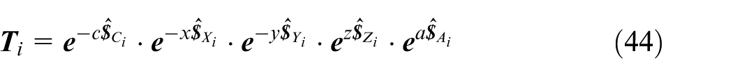
For instance, for X-axis,
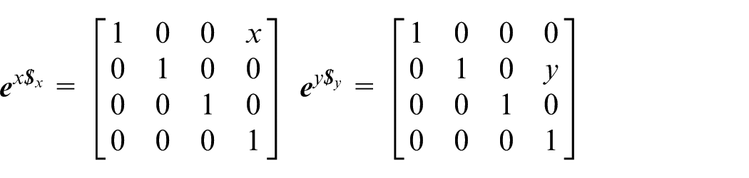
Screws


Corresponding exponential matrices represent transformation of these three screws;
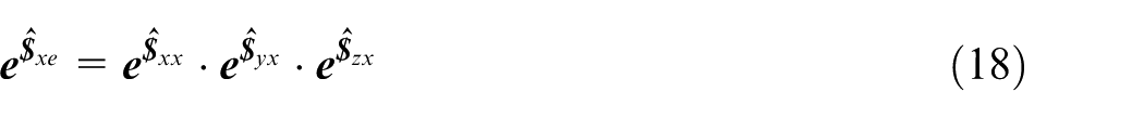
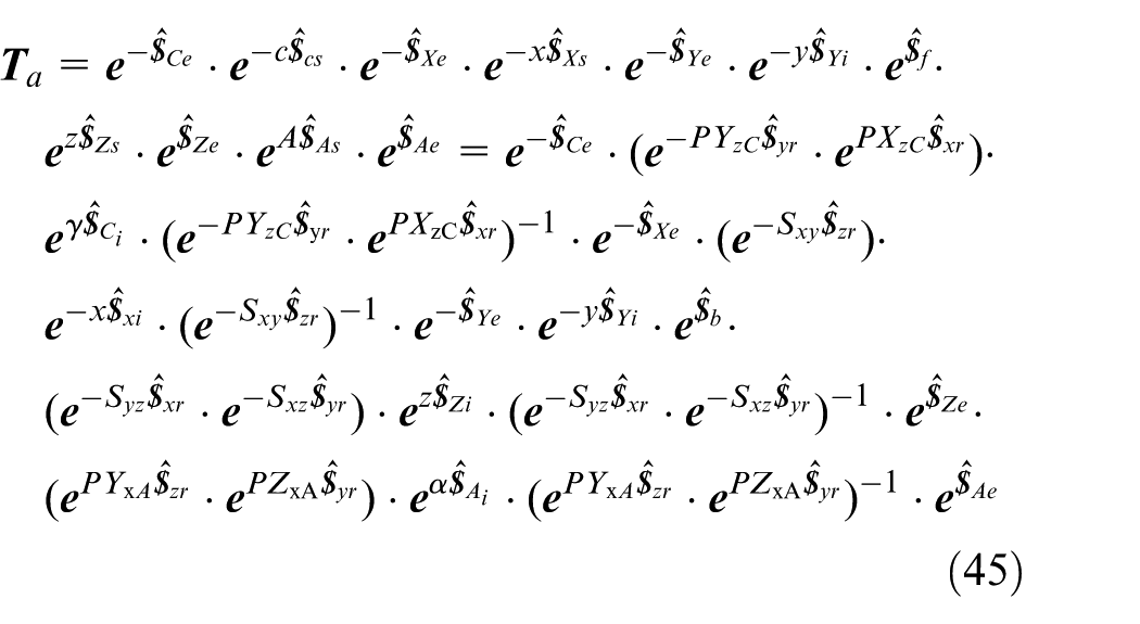
Error model for X-axis is as follows
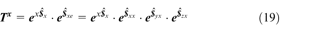
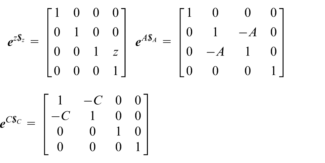
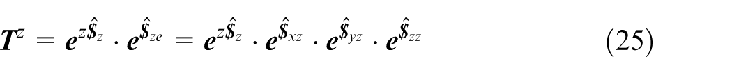
Similarly, error screws for Y-axis and Z-axis were modeled. Comprehensive error models are shown in equations (20)–(25)
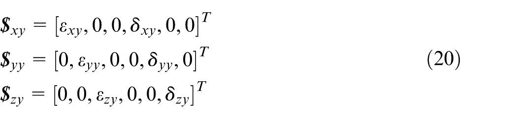
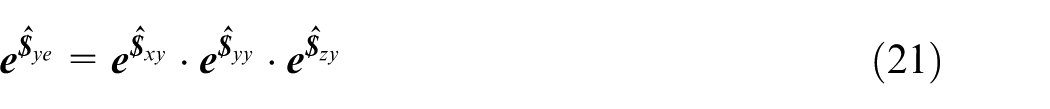
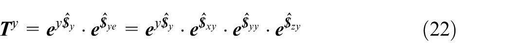

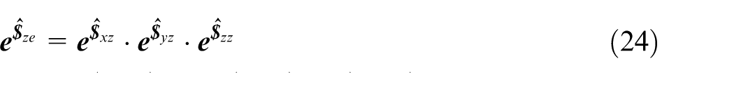
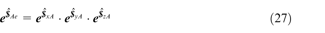
Moreover, corresponding comprehensive error screw models of A-axis and C-axis are as follows

Perpendicularity and parallelism error model
Due to deviation between the actual axis and ideal axis, angle between adjacent axes is not equal to 90° resulting in perpendicularity error. Assuming that the Y-axis as the reference direction, there is no perpendicularity error. Perpendicularity error between X-axis and Y-axis is only perpendicularity error of X-axis. Perpendicularity errors
Taking X-axis as an example, ideal unit motion screw

Perpendicularity error is represented as

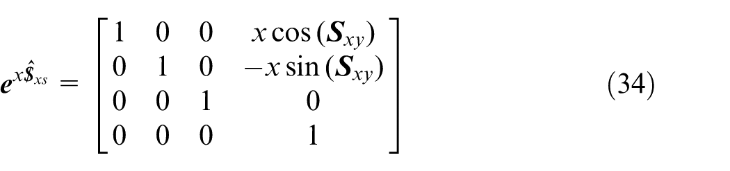
Furthermore, an adjoint matrix can be used to represent coordinate transformation. According to equation (10), the reference coordinate system rotates through an angle around the ideal Z-axis, and this process can be denoted by equation (35)
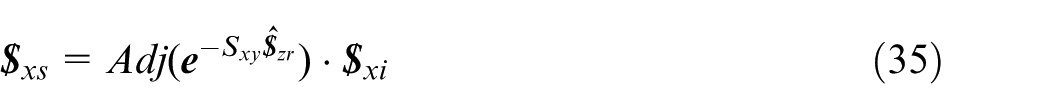

In the above equations, second subscript
Similarly, ideal unit motion screw for Z-axis is represented as
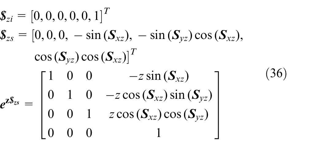
Similarly, considering the adjoint matrix coordinate transformation method, first, the reference coordinate system rotates around the ideal Y-axis, and then rotates around the ideal X-axis. Equation (37) expresses the transformation
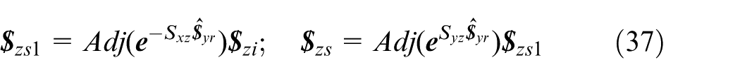
where
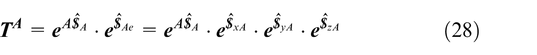
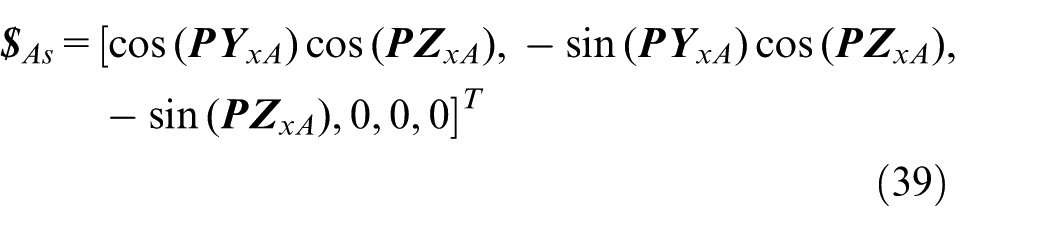
Considering A-axis as an example, ideal rotation unit screw around X-axis is

Considering parallelism errors
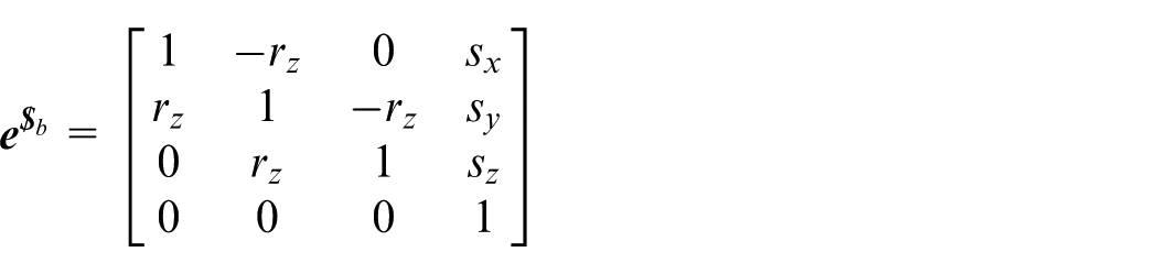
Actual exponential matrix of A-axis
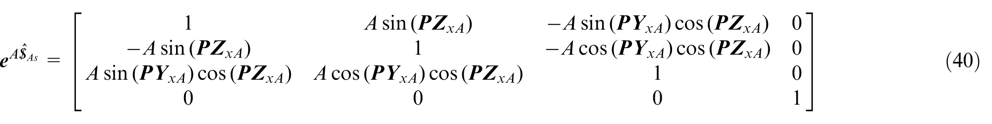
As in the adjoint matrix coordinate transformation method, first, the reference coordinate system rotates around the ideal Y-axis, and then rotates around the ideal Z-axis. Equation (41) shows this transformation
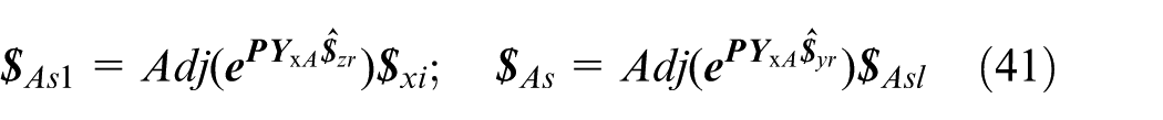
Similarly, the ideal unit rotation screw for C-axis is represented by
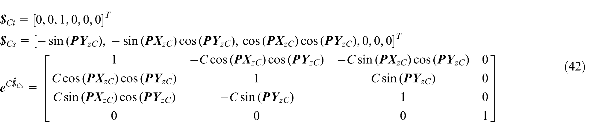
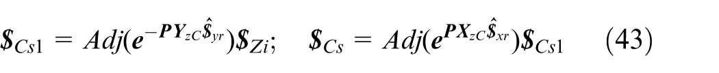
As in the adjoint matrix coordinate transformation method, first the reference coordinate system rotates around the ideal Y-axis, and then rotates around the ideal X-axis. The transformation can be expressed as shown in equation (43)
Geometric model using topological structure
This article applies MBS theory to obtain a detailed topological structure of the machine tool as shown in Figure 6. In addition, the structure is used to establish the geometric error PoE model.
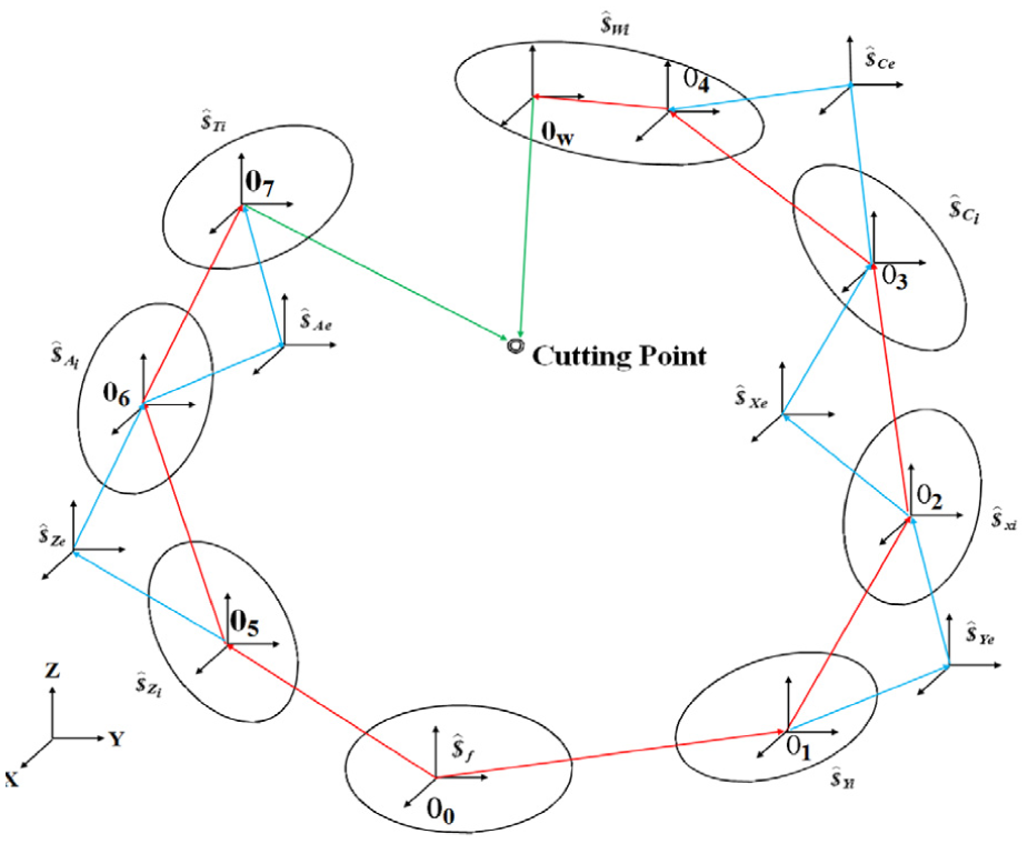
Topological structure of the five-axis machine tool O0: bed; O1: Y-axis; O2: X-axis; O3: X-axis; O4: workpiece; O5: Z-axis; O6: A-axis; and O7: tool.
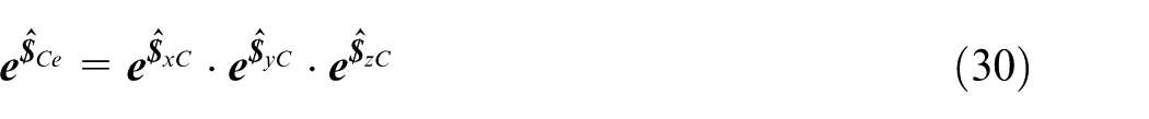
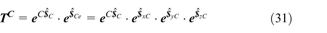
Under ideal conditions, there are no errors. Following the modeling sequence
By adding error screws, perpendicularity errors, parallelism errors, linear errors, rotation errors, and thermal errors, actual PoE model
where
Tool tip error is the deviation between ideal and actual homogeneous coordinates of the tool tip. Error transformation matrix

The tool pose errors are represented as

Tool pose errors can be considered as the difference between the actual and design values of the machining process. In this article, this is considered as the constraint condition of the actual pose for the cutting tool.
Three components of

Installation errors for the tool and workpiece are small and can be neglected. Equations (48)–(50) express Ex, Ey, and Ez, respectively
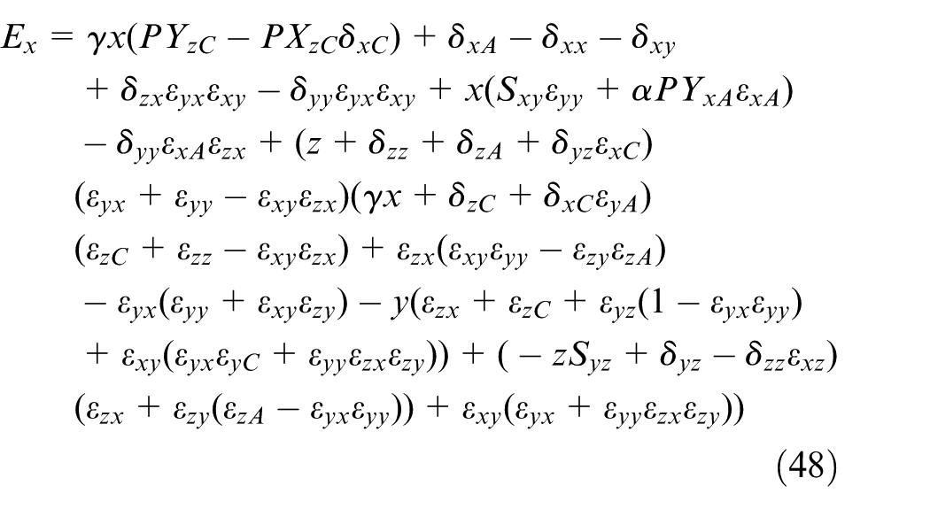
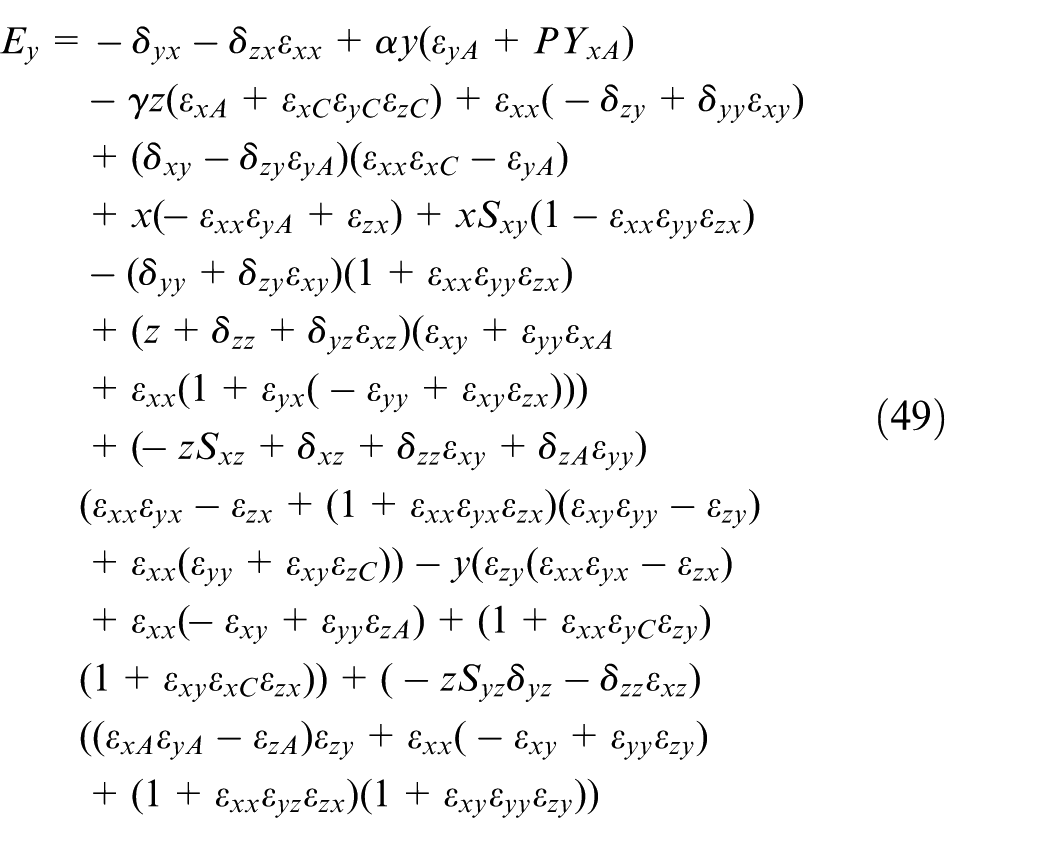
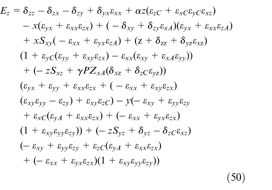
Then, by ignoring second-order and higher order error terms, first-order models are reduced to the following
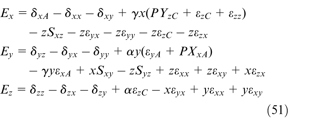
In equations (48)–(51),
Geometric compensation method based on Floyd algorithm
Two main methods used to compensate errors in a CNC machine are as follows: (1) manual adjustment of the NC processing program, which is based on error measurements in machining and (2) NC error compensation by setting parameters, which input prediction terms in advance. In recent years, the compensation method NC tool path planning modified has become a popular and a widely used approach. Planning and solving are the best tool paths. There are numerous tool path planning methods such as parallel to the shortest path search algorithm, ant colony algorithm, methods based on matrix of load balancing incentive algorithm, enhanced bandwidth-inversion shortest-path (EBSP*) algorithm, and Dijkstra algorithm. The Dijkstra algorithm has been frequently used in the shortest path planning. However, the computing process required for this algorithm is time-consuming. Floyd algorithm is a new path planning method that has never been applied to error compensation although it is easy to understand and design.
In the previous section, method to establish geometric error modeling was discussed in detail. Traditional compensation techniques always modify the error terms. The result is that each term is dependent on other terms and reduction in some error terms could result in an increase in other terms. Therefore, a compensation method that merely modifies key error terms is not acceptable or feasible. Currently, error compensation in volumetric comprehensive error seems to be more feasible. This section introduces the Floyd algorithm to compensate errors.
Operating principle of Floyd algorithm compensation
The Floyd algorithm is implemented by calculating the weight matrix. Adjacency matrix D(0) represents the distance between each of the two nodes, such as wi and wj. First, D(1) is calculated. One of all the possible paths is figured out between wi and wj. A comparison reveals the best path. The new iteration adjacency matrix D(1) replaces the original matrix. Elements in D(1) represent the optimal path between two points after one iteration. By adding one node between wi and wj, path changes directly to be better or have a shorter distance. On the other hand, in order to improve the reliability, an iterative matrix
During machine compensation, comprehensive error will deviate the tool point position. In this article, the target wt was decided and compensation method aimed to determine the shortest path. Actual point wj and path length will be
Consider a machine tool operating on the X-Y plane with coordinate point as (xi, yi). Eight different paths may be followed when the tool moves
Distance is
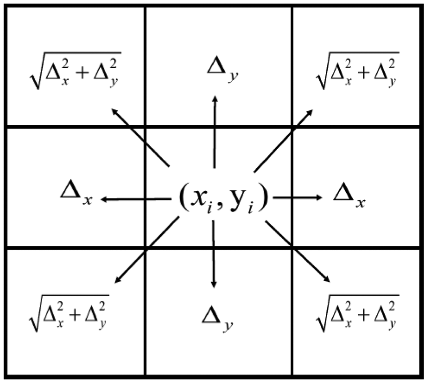
Machine tool working on X–Y plane.
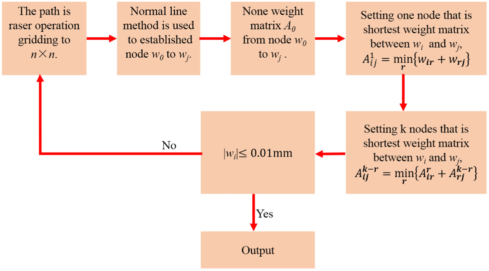
Floyd algorithm compensation flow chart.
Compensation by Floyd algorithm
Result of the present computation method depends on geometric modeling based on PoE screw theory, where other factors are set as invariable. Taking X-axis (X − Ex) as an example (Figure 9), the work field was divided into a 100 × 100 grid.
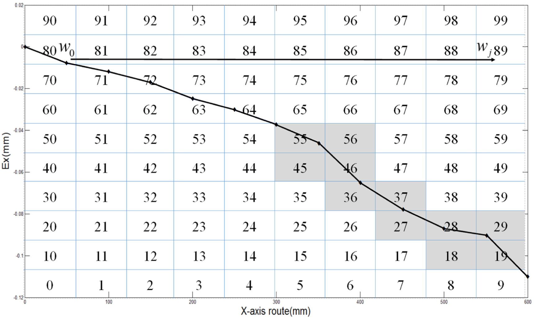
X-axis work field errors grid.
The path of tool from initial node w0 to target wj will deviate from the ideal path due to machine errors. To increase the machine tool accuracy, Floyd compensation algorithm was applied. The first step was to select nodes from path. Vertical line locus (VLL) was used and points of intersection were between normal of tangent vectors to path and grid, which was used to confirm nodes. Selected nodes
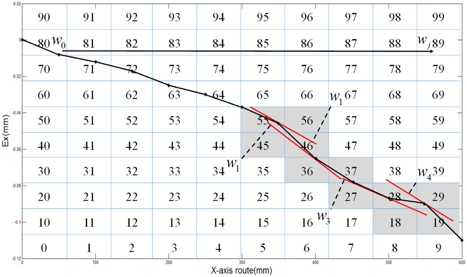
X-axis work field: selected nodes.
Adjacency matrix was calculated according to digraph, and their weights can be defined according to the position of the nodes among w0, w1, w2, w3, w4, wj. Taking S01 as an example, which is the weight between w0 and w1,
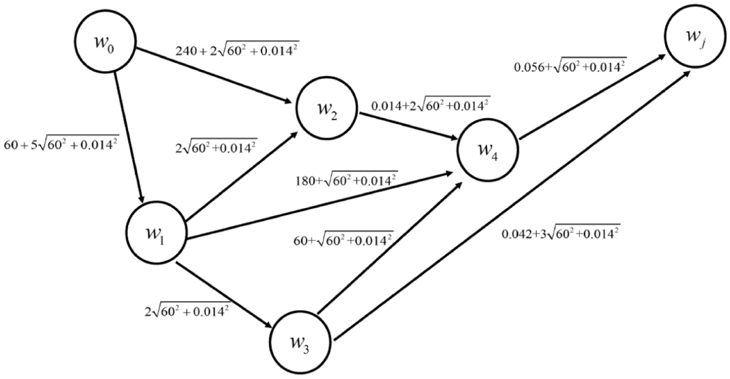
The weighted graph of path.
Floyd compensation algorithm implementation in CNC machine
Floyd compensation algorithm was implemented in three steps:
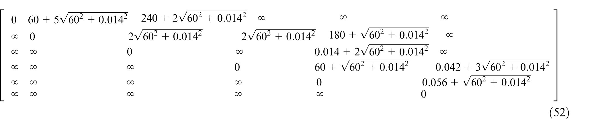
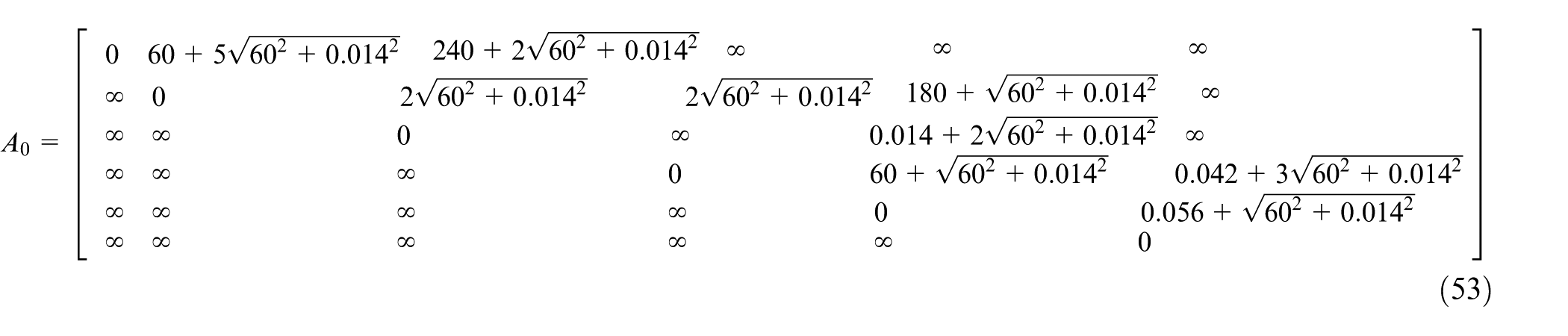
Step 1. Divide the path into an n × n grid. According to the weight matrix, use VLL to select nodes w0, w1, w2, w3, w4, and wj. Determine their relationship and direction weights. The corresponding weight matrix is shown in equation (53)
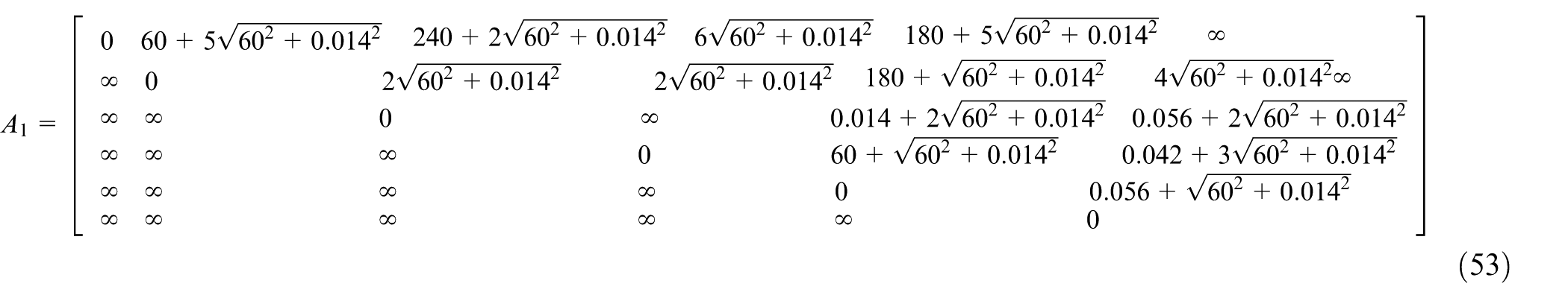
Step 2. Set one node between wi and wj, which is shorter than weight matrix calculated at Step 1. The shorter distance is given by
Step 3. Set
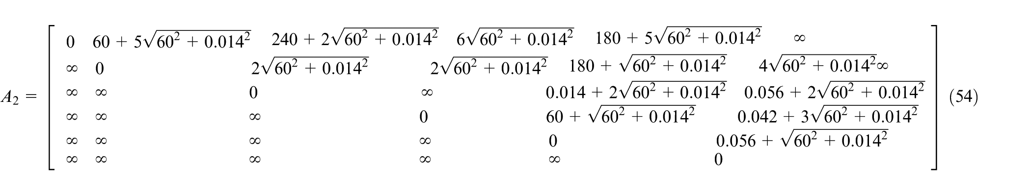
Step 4. Evaluate
Machining errors mainly consist of geometric and other errors. Only in an ideal state, errors can be eliminated. Path through three added nodes or four added nodes is same as in the case of two added nodes. Path from w0 to wj was shorter than that through w2 and w4. Repeating this process for error compensation completes the iteration until the final condition
Comparison between compensated and non-compensated paths.
Design of experiments
In order to verify the effectiveness and generality of the Floyd compensation algorithm, two experiments were designed in this section. The first experiment is a numerical simulation experiment, and the other is the application of Floyd compensation algorithm in the actual processing.
Numerical simulation experiment
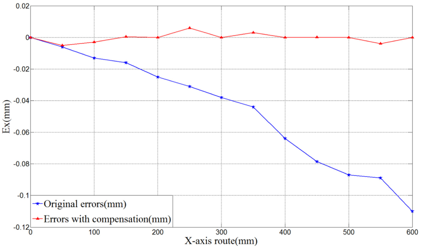
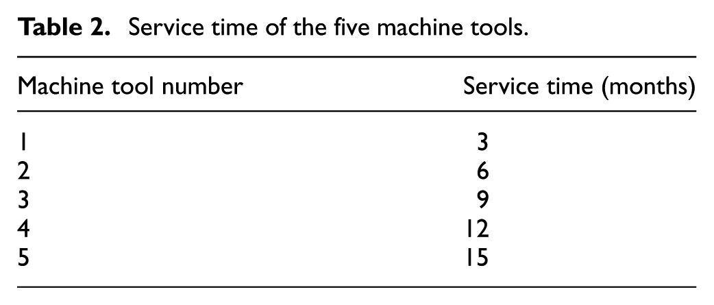
In this experiment, 5 five-axis machining centers of the same type with different use time were selected to carry out experiments, and Table 2 lists the service time of each of these five machine tools. Taking X-axis as an example, Figure 13 shows the positioning errors on X-axis for the different machine tools. The numerical simulation of Floyd algorithm compensation effect for different machine tools is shown in Figure 14. Figure 14 also shows that Floyd algorithm compensation method can limit the positioning errors within the range [−8 µm, 9 µm]. Therefore, this compensation method provides excellent results for different machine tools.
Service time of the five machine tools.
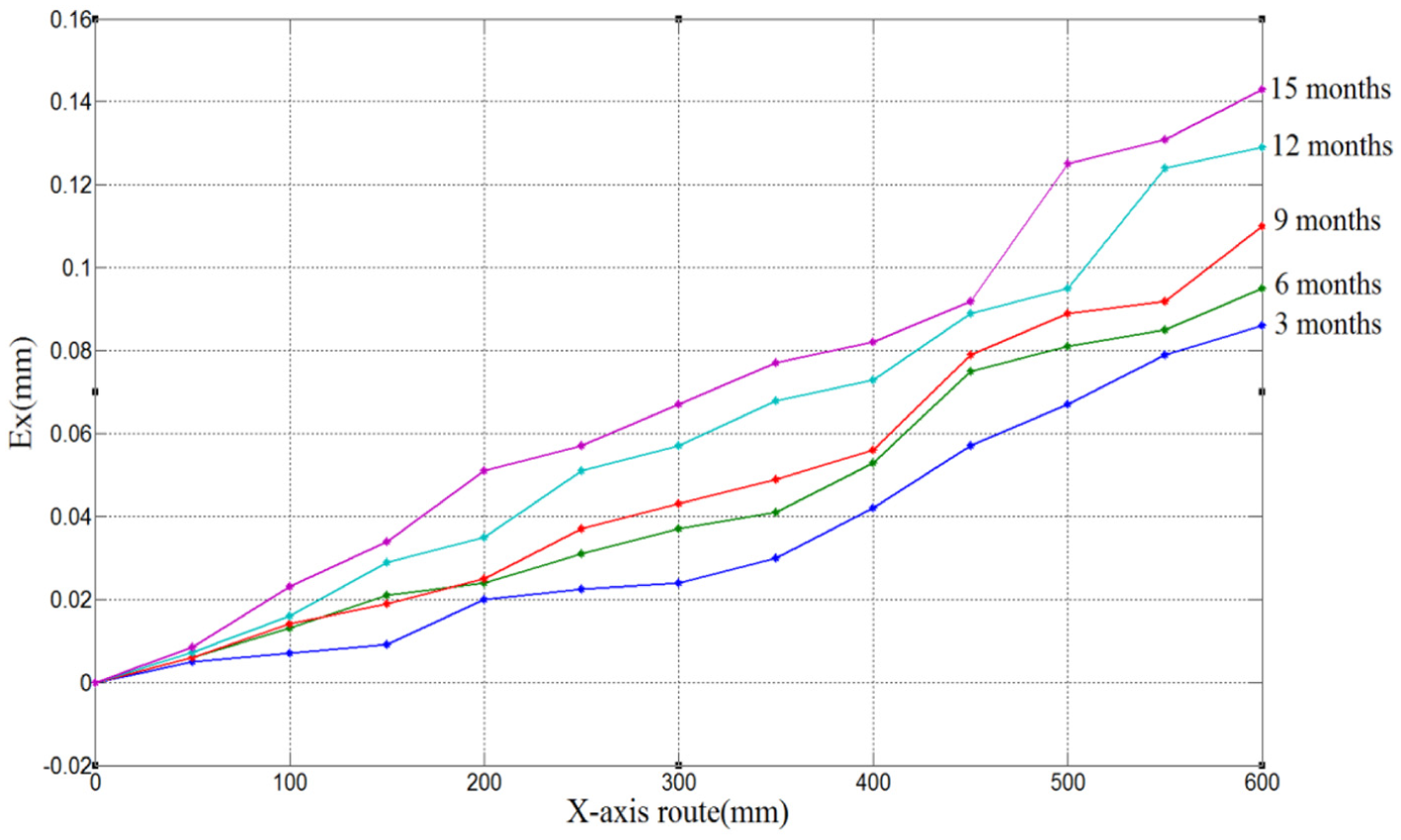
Volumetric geometric errors on X-axis under different machine tools.
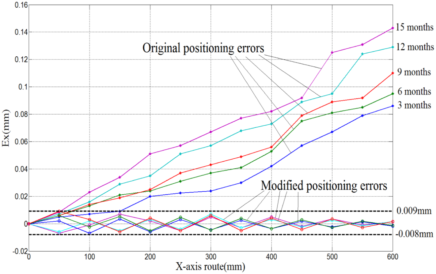
Floyd algorithm compensation effect under different machine tools.
Actual machining experiment
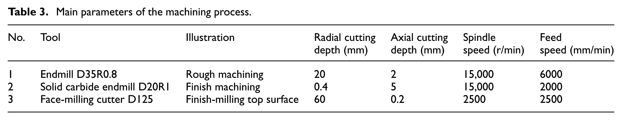
In this section, the effectiveness of the proposed compensation method is investigated by a practical application. According to the Machinery Industry Standard (JB/T 10792.1-2007), a conical table workpiece was selected and machined. Figure 15 shows this conical table workpiece. A five-axis NC machine tool as shown in Figure 2 was selected to carry out the machining experiment. Main parameters for the machining process are shown in Table 3. Tests were conducted by machining two conical table workpieces with and without error compensation, respectively. Each workpiece was measured using three-dimensional (3D) coordinate measuring machine (CMM). The steps of this experiment are as follows:
Step 1. Based on NX8.0, a machining program for conical table was automatically generated. The first conical table workpiece was machined without geometric errors compensation.
Step 2. Next, based on NX8.0, the machining program of another conical table was automatically generated. Floyd path compensation program was used to optimize tool path. Figure 16(a) and (b) shows the path instruction codes before and after compensation, respectively. Figure 17 shows the original path and the compensated path generated by numerical simulation.
Step 3. After the two workpieces were machined, measurements were carried out using the CMM, respectively. Table 4 lists the measurement results.
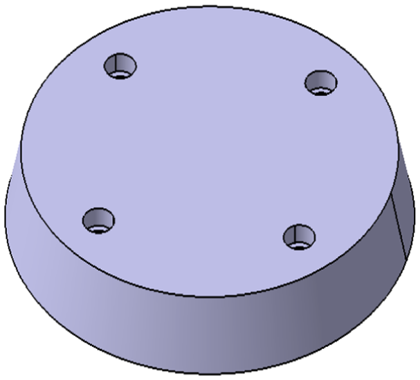
The selected conical boss.
Main parameters of the machining process.
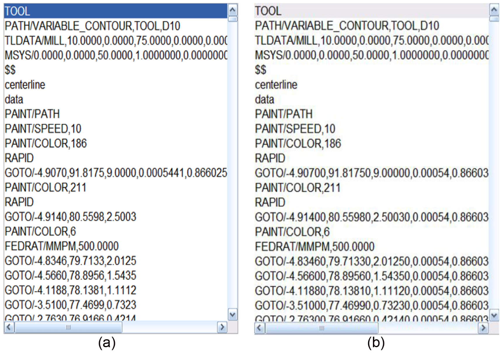
Path instruction code during compensation: (a) before compensation and (b) after compensation.
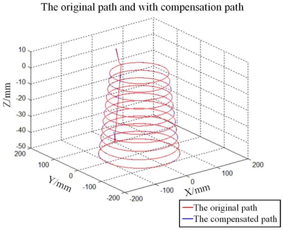
Simulated original path and compensated path.
Measurement results.
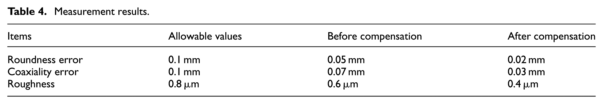
According to the Machinery Industry Standard (JB/T 10792.1-2007), roundness error and coaxial error must be less than 0.1 mm, and roughness value must be less than 0.8 µm. After applying Floyd compensation algorithm path, measured roundness error was 0.02 mm, which is smaller than the value of 0.05 mm measured for the conical table machined with non-compensated path tool. Before compensation, coaxial error was 0.03 mm, after compensation, the coaxial error was 0.07 mm. Moreover, measurements showed that the surfaces of compensated workpiece were more accurate compared to the workpiece machined without compensation. And the value of roughness decreased from 0.6 to 0.4 µm. Based on the results, it can be concluded that Floyd algorithm compensation was effective in reducing machining errors.
Conclusion
This article proposes a new geometric error compensation method for machine tool based on Floyd algorithm and screw theory. According to the improved Floyd minimum-distance method, an error compensation model was established by adjusting weight unceasing. As a result, the algorithm allowed better compensation using fewer calculations. A total of 5 five-axis machining centers were then used to implement experiments. Based on the experimental results, it can be concluded that the proposed method can be considered as universally applicable and effective across machining tools. Actual machining results also show that the proposed method can be considered effective, due to the reduced roundness error, coaxial error, and surface roughness. The experiment results based on the model proved that the new geometric errors compensation method based on Floyd algorithm has the advantage of higher compensation precision.
Despite progress made on the proposed method, methods to compensate or reduce uncertain error terms using the Floyd algorithm have been considered in this article. However, a method to compensate for errors caused by thermal- and load-related parameters still needs further research.
Footnotes
Declaration of conflicting interests
The author(s) declared no potential conflicts of interest with respect to the research, authorship and/or publication of this article.
Funding
The author(s) disclosed receipt of the following financial support for the research, authorship, and/or publication of this article: This work was supported by the National Natural Science Foundation of China (51575010), Beijing Nova Program (Z1511000003 150138), The Leading Talent Project of Guangdong Province, Open Research Fund of Key Laboratory of High Performance Complex Manufacturing, Central South University (Kfkt2014-09), and Shantou Light Industry Equipment Research Institute of Science and Technology Correspondent Station (2013B090900008).