
Abstract
In the field of composite technology, inefficient and poor designs of twist drills contribute immensely to the challenges facing drilling of composite materials. An attempt to report some of the drill design methods and their inherent challenges confronting composite machining necessitates the writing of this article. A critical review has been conducted to offer a clear understanding of the current advances in the field of mechanical drilling of composite materials, focusing on geometry, material and parametric tool designs. The inter-dependable effects of thrust force, cutting speed, feed rate, cutting force and torque on drill design are similarly reviewed. This article also reveals other associated issues facing composite drilling including delamination, surface roughness, rapid tool wear and drill breakage. Well-designed drill geometry and good knowledge of drilling parameters afford the producers of polycrystalline diamond, carbide and high-speed steel tooling materials better opportunity of developing a drill that will minimise delamination of the reinforced composites and tool wear and produce a high-quality surface. Twist drill manufacturers and users will benefit from this article as they seek to have well-designed and improved drills.
Introduction
The kinematics of drilling is a process of using a rotating drill bit to create or enlarge existing round holes in a workpiece. 1 Drilling is one of the most frequent processes used in manufacturing industry among machining operations. 2 Tonshoff et al. 3 noted that drilling takes about 25% of the total machining time and 33% of all the total machining operations of a manufacturing process. It is a preliminary step for many other machining operations, such as reaming, tapping and boring.4,5
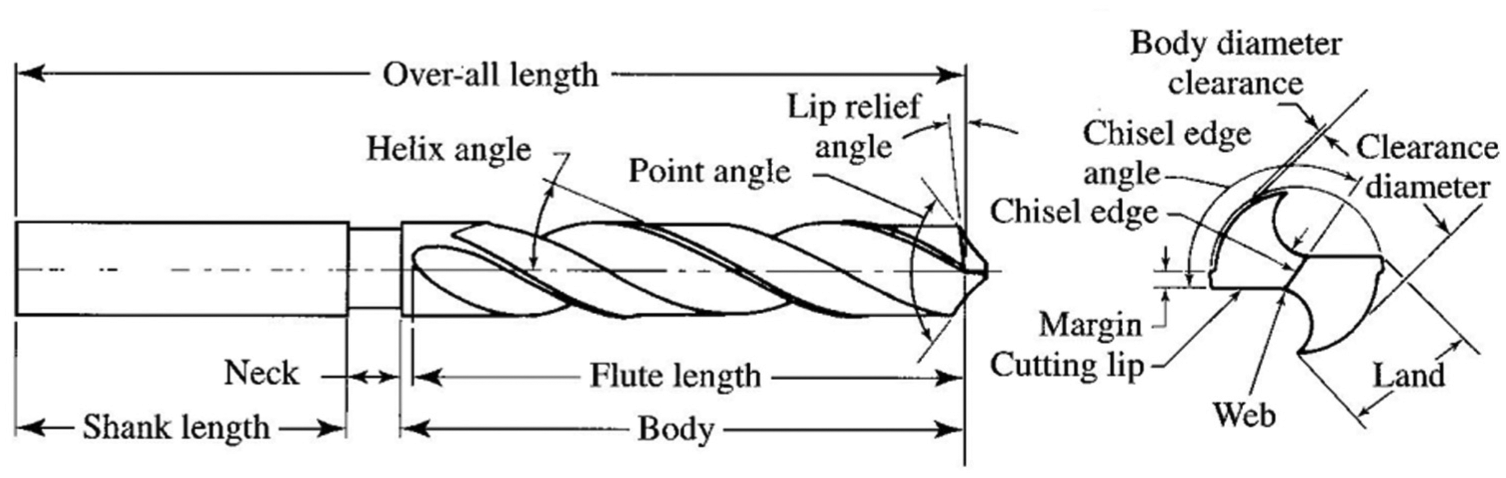
Drill, as a rotary end cutting tool, has one or more cutting lips and flutes for the release of chips and the access of a cutting fluid. Presently, drill bits are the most frequently and extensively used material cutting tools. 6 Geometrically, a twist drill is a complex material cutting tool, as depicted in Figure 1. Both the geometrical shape and dimensions of a twist drill determine the cutting performance and influence the cutting forces, tool wear, cutting dynamics and the quality and integrity of drilled holes.9–12 These make the design of twist drill of critical importance. A poorly designed cutting edge results in an undesired distribution of the cutting angles along the drill cutting edge,13–16 causing inefficient performance, loss of cutting ability and increase in total manufacturing cost.
This article reviews recent advances in twist drill design for machining of composite materials. The main objective is to critically review the literature, focusing on the effect of twist drill design parameters on composite drilling. An attempt is made to outline the fundamental limitations of the currently developed and applied designs. The first part of this article focuses on the variation in geometric design of twist drills, followed by tooling materials with respect to composite drilling; hence, common limitations associated with composite drilling and drilling parameters are lastly considered.
Twist drill geometric design concept
The complexity of the geometry of a twist drill requires careful design consideration. The cutting dynamics, drilling forces and tool wear17–22 strongly depend on the drill dimensions and geometry. The machine tool requires much more energy and power when its cutting tool is poorly designed, in addition to tendency of damage on the machine.
Fetecau et al. 23 reported that the efficient approach to reduce drill wear in order to increase the drill performances is to have well-defined geometry of the main cutting edge only, such that it could lead to a constant unitary energetic load along the main cutting edges. In an attempt to redesign a drill for an optimum performance, the flute profile has often been designed by incorporating ‘forward’ and ‘backward’ simulation analyses, to decide on an optimum geometry of the flute grinding process. 24 Straight lip and parabolic heel flute profiles, computer-aided design (CAD)/manufacture software were used to establish a design flute profile from the drill specification. The application of the software and model to flute showed that the required wheel profile parameter with respect to the diameter could be represented by simple regression equations.
Piquet et al. 25 studied the drilling of thin carbon/epoxy laminates with two types of drills: a helical drill and a drill without chamfer on the cutting edge, made up of high-speed steel (HSS) and ‘micrograin’ tungsten carbide (K20 rating), respectively. It was concluded that both drills caused damage at the entrance of the wall and the exit of the hole, but K20 tungsten carbide geometry drill produced reduction in the final damage.
Cutting edges and angles
The design of cutting edges has focused on point design with consideration of cutting forces for arbitrary cutting geometries, 26 stress analysis 27 and design and optimisation using simplified drill geometry models.28–32 The majority of the drill geometrical improvements have often been limited to the chisel edge region. This proved to be effective in reducing the total thrust force, but marginally reduced the torque and the power which are the major determinants of the tool performance. 2 Furthermore, significant design features such as reverse web taper and internal cooling channels, cutting lips and chisel edge geometries including verification of grindability which is important for the drill cross-sectional design have been reported to be considered in an acceptable drill geometry model. 33
Thinned purpose and faceted point together with the patented ‘circular centre edge’ designs have been developed, using predictive force models. 34 The predictive mechanics of cutting models for thrust and torque were numerically and experimentally tested and found that the drill designs substantially reduced the thrust force when compared to un-thinned drills and differences in the forces for the three designs were minimal after comparison.
A practical method to determine the cutting edges and rake angles has been carried out by Li et al. 35 Cutting edge points and the rake angles were examined using two-dimensional (2D) tool microscope and image-based instrument and numerical computation, respectively. This method proved effective compared with common unaffordable laborious analysis required in rake angle determination, because it does not require high level of co-ordinate transformation and mathematical competence.
Lip geometry
Sambhav et al.36,37 established a methodology to model the geometry and cutting forces of drills with generic point. With the aid of non-uniform rational basis spline, CAD geometric models were used for a fluted drill in terms of bi-parametric surface patches. Generic and mechanistic models were presented for the cutting lip and chisel edge and prediction of the forces, respectively. The mechanistic model was applied to calculate the forces for each element and determined the drill total thrust and torque. Similarly, a new paradigm to model various twist drill geometries in terms of three-dimensional (3D) parameters was established by Tandon et al. 38 Their work outlined the construction of a detailed CAD model for a fluted tool. A new well-detailed and broad 3D definition of the drill geometry was established.
Point angle
Durão et al.’s 39 experimental techniques showed that the most effective tool was 120° point angle drill for minimal delamination and at higher feed rates. They reported that a good alternative could be a step drill designed for a particular composite although presently, not yet available commercially. Vijayaraghavan 40 reported a tool which could generate automated 3D CAD drill geometric models and manufacturing parameters as a required component of numerical/finite element analysis (FEA) models of fibre-reinforced polymer (FRP) drilling. The outputs of the tool gave a variety of solid geometry formats of drills, and through meshing; it was used in different FEA packages.
Drilling of thick fabric woven carbon fibre–reinforced plastic (CFRP) composite laminates was experimentally performed, using uncoated carbide (UC) and diamond-coated carbide (DCC) twist drills. The effects of the geometries of double-pointed angle drills were investigated. 41 The UD, DCC-I and DCC-II have 6.35, 6.91 and 6.38 mm diameters; 140°–60°, 130°–60° and 140°–60°drill tip angles, respectively, with rake, clearance and helix angles of 7°, 11° and 30°, respectively. The geometries of both UD and DCC-II drills were the same, while the tip angles, primary and secondary cutting edge lengths of DCC-I and DCC-II drills were different. The diamond particle size as well as the coating condition and thickness determined the performance of the drills. It was concluded that the geometry of DCC-II was appropriate than the DCC-I drill during high feed drilling of the composite material, producing critical hole diameter tolerance than delamination drilling-induced damage.
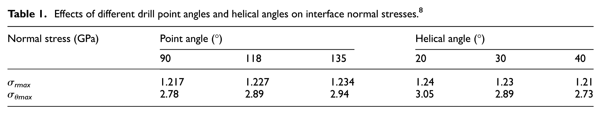
Chao et al. 8 stated that edge radius has the greatest effect on the interface stresses by deposition. Tensile radial normal stresses affected the reliability of the coating bond and changed helix angle, point angle and web thickness. These stresses influenced a difference in drill tip from 10° to 20° point angles. Meanwhile, point angle increased with the normal stresses unlike helical angle, as shown in Table 1, where σmax is the maximum stress, although depends on the tooling material, but decreased with delamination.39,43 Stresses on the tool reduce its life. Kilickap 44 observed that an increase in HSS drill point angle leads to a decrease in delamination effect during unidirectional-ply glass fibre–reinforced plastic (GFRP) composite laminate conventional drilling. During drilling (high-speed and conventional) of woven-ply CFRP, Gaitonde et al. 45 reported that cemented carbide (CC) K20 point angle increases with an increase in delamination damage.
Effects of different drill point angles and helical angles on interface normal stresses. 8
Lip flute profile
Armarego and Kang 24 reported that the generated lip and heel flute profiles closely formed the ideal profile for the creation of straight lip and a parabolic curve, respectively, with the curve being tangential to the web diameter and passing through the corresponding heel corner. A multi-objective geometry optimisation was realised by Sardiñas et al. 46 by implementing meta-heuristic algorithms. The subsequent geometry was validated and verified by constraint functions including chip flute grindability verification.
Tooling material selection
Tooling material influences drilling-induced damage, such as delamination effect,17,18,47 and the variation in cutting forces 48 which have significant effects on both drill life and the structural integrity of composite materials.
Drill tool materials
The life of a drill depends mainly on hardness, toughness, wear and thermal resistance. A good drill must possess the ability to resist wear, fracture, quick rupture and retain hardness at the state of hot hardness. The major properties of different tool materials are shown in Figures 2 and 3. From these figures, the hardest tooling material, polycrystalline diamond (PCD), possesses least toughness property as its sharp deformation occurs around a temperature of 600 °C unlike HSS with the best toughness, but deforms around 700 °C when compared with other tooling materials.
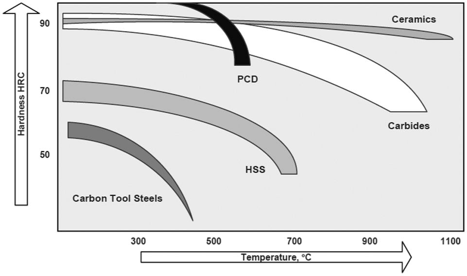
Relationship between hardness of drill materials and temperature. 49
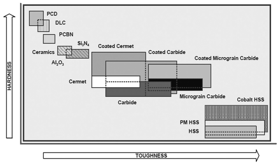
Relationship between hardness and toughness of drill materials. 49
HSS
Liu et al. 50 reported in their review study of drilling composite laminates that HSS or carbide drill bits have primary attraction based on better performance at high cutting speed compared with other drill bits. Some studies51–53 used HSS drills frequently, making it the most widely used tooling material due to its availability, low cost and highest toughness, as shown in Table 2. It has a highest percentage (47%) of applications; 24 applications of 51 research works were considered.
Various twist drill materials for drilling composite laminates.
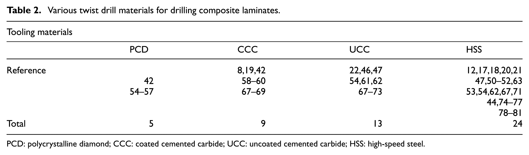
PCD: polycrystalline diamond; CCC: coated cemented carbide; UCC: uncoated cemented carbide; HSS: high-speed steel.
CC
Carbide drills performed better in terms of wear resistance, delamination effect and surface finish when compared with HSS under comparative low speed and feed at high temperatures when drilling the same composite materials,21,47,52,54,61,62,67 as indicated in Figures 2 and 3. When the radius apart from the corner was measured, almost null wear land was shown in the flank surface of carbide drills, while HSS drill had considerable wear. 52
PCD
Garrick 55 reported producing a veined drill that was capable of drilling carbon composites and its stack with titanium. However, he observed that after 200 holes had been successfully drilled, a wear land was formed on the cutting edge of the 86 series PCD veined drill which necessitated re-sharpening of the drill. In addition, it was reported that in order to strengthen its cutting edge and make PCD drills viable, it might require modification with k-lands. Also, further suggestion was made that an assessment of the drill process and delamination would be useful in the design and optimisation of new PCD drill geometry that might give a better output. Investigation of the effect of the cutting parameters on drilling carbon/epoxy and carbon/peek was done by Chambers and Bishop. 56 They concluded that the drilling of carbon composites is dependent on the characteristics of the matrix. The helical PCD drill geometry gave the best overall performance when compared with other CC drills, but more reactive to feed rate changes, when delamination was considered. 54
Heath 57 reported that PCD being a stronger tool material could be used for machining of composites because of its ability to withstand the severe abrasion of the carbon fibre–reinforced composites (CFRCs). However, PCD is found to be too fragile to withstand the high cutting forces required for metal such as titanium 57 especially when stacked with composites. Furthermore, the configuration of the core drill had been proved better than the traditional twist drill. Therefore, the outstanding advantages of core drilling using a solid PCD drill have been reported by Butler-Smith et al. 82 A novel designed core drill produced 26% reduction in thrust force, reduced drill surface clogging, cutting force and drilling temperature, producing reduced delamination damage possibility during composite drilling. The novel micro PCD core drill possessed laser-generated cutting micro-teeth formed onto a tungsten carbide backing. The performance of this novel drill was experimentally compared with electroplated diamond tool during micro-core drilling. The electroplated diamond micro (EDM) core drill produced cutting forces that were 36% and 190% greater than PCD core drill at new state of the tool and after 216 drilled holes, resulting in terrible composite delamination. Similarly, up to 11% and 25% greater drilling temperatures were generated by the EDM core drill than the PCD core drill at new state of the tool and after 216 drilled holes. Also, at 216th hole, 1.8 times higher thermal spread was produced by EDM core drill than the PCD core drill.
Problems associated with drills
Rapid tool wear
Tool wear is an unwanted phenomenon in machining process, whereby the tool loses an amount of matter. It affects the quality of the drilled surfaces (holes) and geometry of the material workpiece. The chip produced during the drilling of carbon composites is abrasive dry powder. The ineffective extraction of these chips is one of the major reasons for high tool wear rates. The most common type of wear, crater wear, occurred to a major extent as a result of discontinuous chip formation and caused flagging of the tool which propped up cutting edge chipping. 54 The cutting force increased with the workpiece–drill tool interface temperature, followed by the increased drill wear and resulted in workpiece deflection and drill bit breakage. 83 The flank wear decreased near the corner of the drill chisel edge, while the maximum flank was common at the drill outer corner. An increase in thrust force, torque on the drill bit and the number of drilled holes caused a proportional increase in the drill tool wear. 83
There have been some researches on the tool wear processes during drilling of carbon composites, as well as the effect of tool wear on the drilling forces and quality of the holes produced. Some investigated the drilling process and correlated it with delamination, while others correlated the drill geometry and feed rate to delamination.43,61,80,84–87
Karpuschewski et al. 74 reported that consistent rounding of the drill cutting edges improves the quality of the corner edges and tool surfaces that form the cutting edge, citing that rounded corners allow the avoidance of run-in periods. Consequently, the high wear of the drill is reduced which leads to 80% increased tool life. Ramkumar et al.78,79 and Zhang et al. 76 stated that vibration-assisted twist drill could be used to improve drilling operations and reduce wear. Lin and Chen 88 concluded in their study on drilling CFRC materials at high-speed that an increase in the cutting velocity led to an increase in the drill wear which directly caused an increase in the thrust force. Furthermore, an analysis and monitoring of occurrence of a flank wear on a 10-mm-diameter twist drill tool had been carried out effectively by Sivarao, 83 using Mamdani fuzzy inference system (FIS). He reported the reliability of the fuzzy application as a tool condition monitoring technique. Statistical and mathematical methods have been used comparatively, to determine the wear on two 10-mm-diameter twist drills during drilling operation. 89 The drill tools X and Y experienced the same process parameters, but slightly different in specification. Drill tool X had 57 HRc, 86 mm and 136 mm, while tool Y possessed 55 HRc, 87 mm and 133 mm of hardness, flute and overall lengths, respectively. Drilling operations were carried out with and without lubricant conditions. Tool wear analysis was performed by applying regression analysis and inverse coefficient matrix (ICM) method, considering the following drilling variables: thrust force, feed rate, cutting speed and drilling time. In both drilling conditions and within drilling parameters selected, the results obtained from the statistical analysis were much better in terms of accuracy and reliability, when compared with the expected values obtained from the mathematical analysis. Also, tool X proved superior to tool Y in terms of design, quality and functionality.
Wear mechanisms of PCD and tungsten drills when drilling CFRP stacked on the top of titanium (Ti) have been studied by Park et al. 42 The wear rate and progression of the tool surface were periodically monitored using a scanning electron microscope and a con-focal laser scanning microscope. Micro-chipping was observed at the cutting edges near the PCD drill margin which reduced the tool performance. Major chipping was observed at the cutting edges when drilling titanium as a part of the constituents of the stacked composite due to the brittle nature of the PCD. However, the PCD drill was comparatively better than a tungsten drill tool in terms of wear resistance.
Edge chipping and breakage
Edge chipping is a process whereby small pieces of the drill are removed or cut off as a result of high cutting and thrust forces, as depicted in Figures 4 and 5.90,91 Ineffective removal, control of the various chip formation, poor cooling of the drill and improper selection of the drill point angle, helical angles, chisel edge and inadequate knowledge of the composite materials could lead to a reduction in tool life and eventually tool breakage. These occur when there is no effective space between the tool and workpiece due to poor design of drill geometry and thermal resistance, causing catastrophic increase in drill temperature.
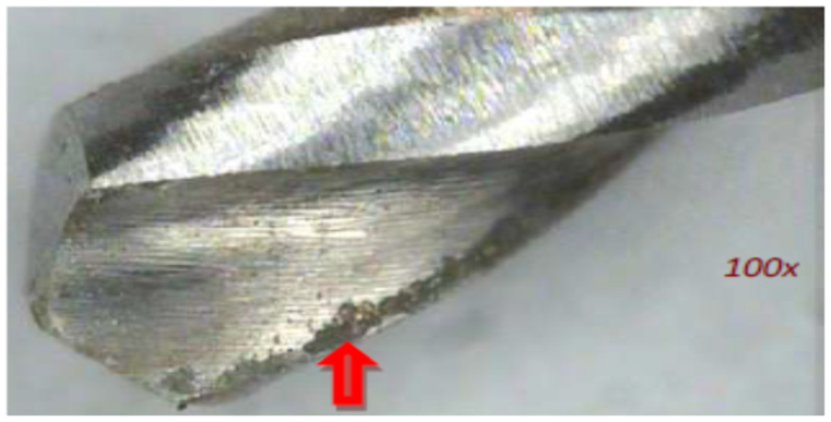
Twist drill edge chipping type of wear at lip. 90
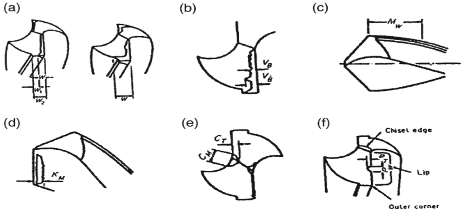
Types of drill wear: (a) outer corners, (b) flank, (c) margin, (d) crater, (e) chisel edge and (f) chipping. 91
Tool coatings
Improvement and better performance of twist drill life could be achieved, especially at high cutting parameters such as cutting speed and feed rate and, during dry machining, by coatings. 49 Coating increases wear resistance, surface quality of drilled composites, corrosion resistance and oxidation resistance. Other factors include coefficients of friction, interface temperature and thermal energy that aids wear could also be reduced using appropriate coatings on correct drill bits. Coatings are rampant on both CC and HSS drills.
Coated CC
Drill geometry effects on the deposition residual or interface stresses in DCC drills have been investigated by Chao et al., 8 through the performance of a solid modelling of diamond-coated two-fluted twist drills. They concluded that diamond-coated drills have a potential for high-performance drilling and for drilling of difficult-to-machine materials. Researchers have concluded that coated drills performed better than the uncoated, as a result of their increased wear resistance and consequently improved tool life.60,64,65,92
Coated HSS
Investigation on effectiveness of WC-8CO electro-spark coating (ESC) on HSS drills has been reported by Raju et al. 75 They stated that ESC performance enhances the drill bit life, as high as fivefold compared to the uncoated HSS drills, based on the machining conditions of variable spindle speed at fixed feed. In comparison to bare drill bit, ESC-coated drills performed better in terms of tool life even when drilling at higher speeds.
Performance and effects of tool coatings
The better or improved performance of drill bits is achieved through coating. In machining technology, several processes have been used in coating cutting tools. In the past, nearly 40 years, the thermal diffusion and thin-film processes have been well and rampantly used. Also, it could be chemical vapour deposition (CVD) and physical vapour deposition (PVD) coatings. Contemporarily, 40% and 50% of HSS and super-hard tools, while 85% of carbides utilised in company are subjected to coating, either on the substrates or entire tools. 49 The later application attracts more cost. The coating method could be a combination of multiple layers. Among the tooling materials, carbides have been found to be an excellent substrate, irrespective of the types of coatings, including solid lubricant, soft, hard or super-hard, single and multi-layer coatings, as well as PVD: chromium nitride [CrN], titanium nitride [TiN], titanium aluminium nitride [(Ti,Al)N)] and titanium carbonitride [TiN(C,N)], to mention but a few. 49 Audy 93 performed a comparative experimental and quantitative investigations on TiN, Ti (C,N) and Ti (Al,N) coatings and found that Ti (Al,N) coating produced the lowest force components and ‘edge’ forces, using cathodic arc evaporated PVD coatings. Sivarao et al. 94 have reported in their experimental work that the TiAlN-coated 8-mm-diameter twist drill tool performed better when compared with the TiN-coated type, under the same dry drilling conditions and parameters in terms of reduction in burr formation (height). However, using 5-mm-diameter drill tool, TiN coating proved better when considering the cap formation. The characteristic performances of these coatings are based on their ability to function at high speed, high temperature and dry or semi-dry condition of machining.
In addition, Iliescu et al. 58 had modelled and experimented the uncoated and Balzers (BS) and Cemecon (CN) diamond-coated twist drill wear in CFRP drilling. The drills were manufactured by Diager and Sofimag manufacturer. The results obtained revealed higher life expectancy of the CN diamond-coated drills than the BS-coated type, while the Diager and CN coatings were better than the BS coating. Furthermore, in a single shot conventional drilling operation on 30-mm-thick Ti-6Al-4V/CFRP/Al-7050 stacks, a comparative experimental evaluation of the effects of diamond-like carbon (DLC) and CVD diamond tool coatings on drill wear modes and quality of drilled holes was carried out by Kuo et al. 95 The DLC and CVD diamond-coated drills experienced abrasion (and brittle fracture) wear mechanism initially and untimely flaking/delamination of the coating primarily, respectively. They concluded that the holes drilled with CVD diamond-coated drills were clearly better than holes produced with DLC-coated drills, in terms of burr reduction and when circularity was considered.
Drilling of composite materials
Composites refer to physically and chemically joined materials of dissimilar phases which are separated by a distinct boundary (Figure 6). The dissimilar systems are joined together in a bid to achieve structural and desirable properties which are unattainable homogeneously by each constituent. 92 Composites have become attractive materials today with various applications such as defence or military (naval and marine), transportation (automobile, marine and aerospace), structural (houses and buildings), communication and manufacture engineering as high demand for materials of low weight, high strength, required stiffness and resistance to high wear, shear stress, impact, fatigue and temperature is increasing.96–102 Carbon FRP composites are rampant workpiece in experimental composite material drilling.
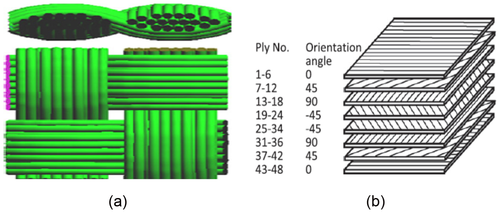
(a) An orientation ply of bi-directional fibre and (b) schematic representation of unidirectional-plie CFRP composite laminate. 50
Composition of carbon fibre composites
Composite is basically made up of fibres and a matrix. Carbon fibre contains textile, melt-spun, polyolefin and lignin. Table 3 depicts some constituents of a CFRP composite laminate.
Constituents of a typical CFRP composite laminates. 45
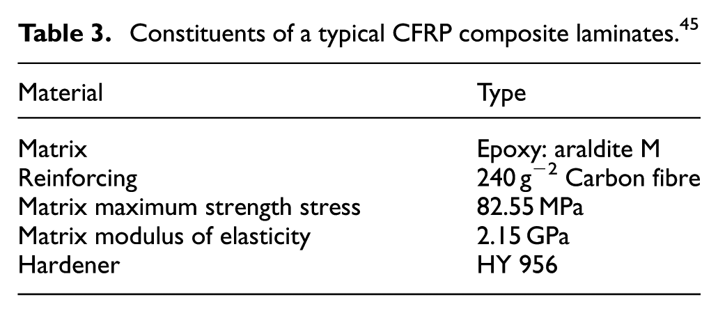
Carbon fibre and matrix formed the reinforcement material and binder of a typical CFRC, respectively. Carbon fibre has good mechanical properties in terms of strength and modulus of elasticity.
The mechanism of drilling composites is a process different from that of conventional materials (especially metals and their alloys) for a good quality hole to be obtained. 99 Velayudham et al. 103 stated that due to the coexistence of hard abrasive fibres and a soft matrix, there is need for an appropriate selection of cutting conditions. Carbon fibre composites have a challenge of poor machinability as a result of their highly abrasive nature, which limits its applications. This causes its fast replacement with natural fibre composites. There are damages caused on the drilled composite materials as a result of their composition such as delamination, hole dimensional inaccuracy, surface roughness, fuzzing and composite fibre pull-out or uncut fibres.99,104,105 The damaged composite materials are susceptible to fatigue strength and load bearing capacity. 105
Problems associated with drilling of CFRC laminate materials
Kim and Ramulu 47 reported that for years, carbon fibre composites have been drilled using the same methods applied in drilling metals. These have resulted in poor finish quality and excessive tool wear. 47 Abrasive, heat sensitivity and heterogeneous nature of composite materials make its drilling a complex operation. 52 For applications where quality demand is high, drilling of the composite structures remains a major challenge, especially where carbon-reinforced composite is stacked to metal parts.22,47 This scenario increases the severity of the problem and requires a more robust specially designed drill and better drilling processes.
In addition, drilling of carbon fibre laminates has several common problems. These setbacks include surface scorching, delamination, excessive tool wear, fibre cratering, matrix melting and softening. 106 Among these, delamination is the most critical defect as it has the highest level of impact on accuracy and quality of a drilled hole.54,105
Delamination
Delamination in a composite material occurs whereby reinforced fibre plies separate, either by peel-up or push-out phenomenon. This defect occurs at the upper most layer of the laminate from the rest of the body and/or on the drill bit’s tip which pushes the bottom layers of the laminate, respectively77,107 (Figure 7). In drilling, delamination occurs mainly at the critical entry and exit locations of the drill bit when the thrust force is greater than a threshold value.59,68,73,104 Delamination depends on many factors such as composite fibre nature, drilling parameters, drill design and laminate orientation. When the drill tip exerts compressive thrust force on the uncut composite laminate plies, and the point loading is greater than the inter-laminar bond strength of the composite, delamination occurs. It reduces composite dimensional accuracy, structural integrity, surface quality and durable applications.52,54,104 Madhavan and Prabu 54 indicated that an increase in cutting speed reduces the delamination for HSS drills, whereas an increase in feed rate increases the delamination effect in case of carbide drills. An analysis of the differences in delamination mechanisms has been carried out by Capello 63 when drilling laminate composites with and without a support device placed under the workpiece. His results showed that the proposed device drastically reduced delamination.
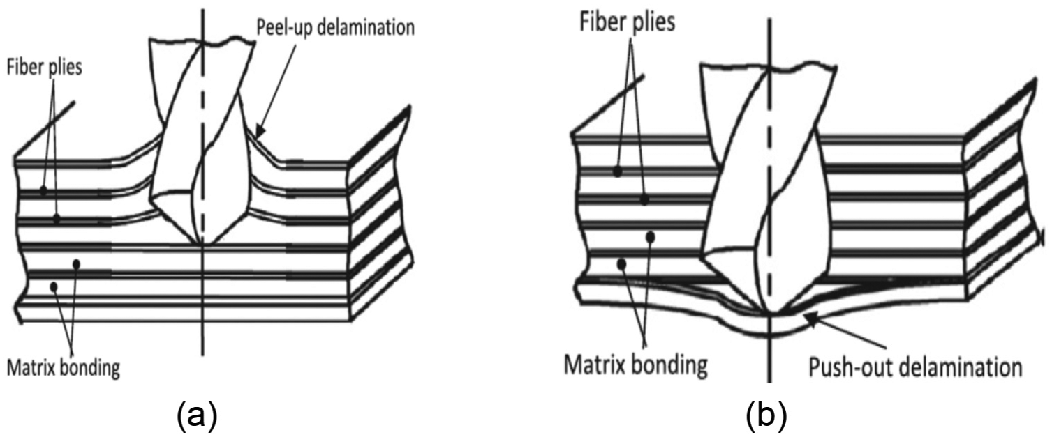
Types of delamination phenomena: 50 (a) peel-up delamination and (b) push-out delamination.
An analytical approach to identifying the process window of chisel edge length concerning drill diameter for delamination-free drilling has been studied by Tsao and Hocheng. 108 The approach was based on linear elastic fracture mechanics of fibre-reinforced composites. An optimal range of diameter of pilot hole associated with chisel edge length was derived. They concluded that composite laminate drilling at higher feed rate without delamination damage could be conducted by controlling the ratio of chisel edge length and preferring medium to large holes. Isbilir and Ghassemieh 109 studied that the delamination-free drilling process might be obtained by the proper selections of drill point geometry and the process parameters: high spindle speed and lower feed rate. They showed that effective tool choice could minimise delamination effect. Importantly, the use of higher feed rates is achievable provided there is sufficient knowledge of the effects on thrust force and delamination for each selected drill.
Analytically, Fd has been generally used17,52,54,69 to describe the intensity of damage on the composite both at the drill entry and exit. It is expressed as Fd = Dmax/D, where Dmax and D are the maximum diameter of the delamination zone and the drill diameter,100,110 respectively (Figure 8). The higher the Fd, the greater the delamination effect.17,69,110
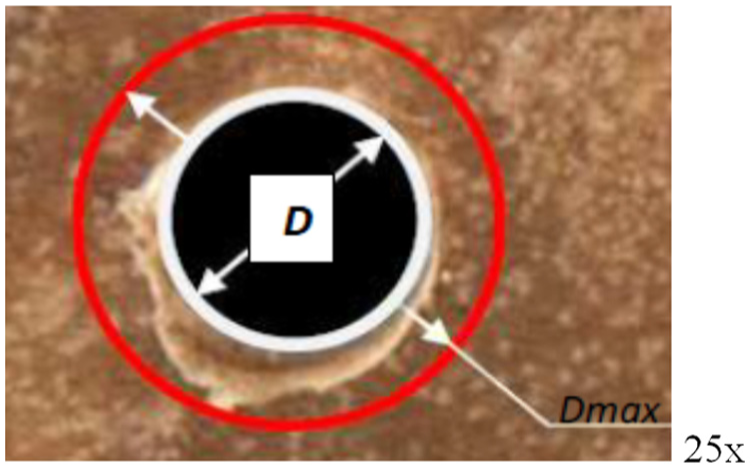
Analysis of determination of delamination factor.
Surface roughness and dimensional inaccuracy
The importance of surface integrity, quality, dimensional and geometric tolerances of holes when drilling CFRP composites can never be compromised. Surface roughness is basically measured using two distinctive methods: direct and indirect methods. The former involves the use of stylus (contact) instruments and the later depends on optical (non-contact) instruments. 5 As a result of the nature of some composite materials, very little has been accomplished to improve on surface roughness and dimensional integrity.21,22,61,65,71,73 The roughness of the drilled surface has not been accounted for as a major issue based on its application. 111 In addition, formation of burrs and caps is another cause of dimensional inaccuracy, as reported by Sivarao et al. 94 They both reduced the fatigue life of the assembly components. Burr occurred as a resultant effect of a plastic deformation of a material under machining process (drilling). Practically, the burrs formed at the entrance of a drilled hole are usually smaller than the exit burrs. 94 The surface roughness in drilling with two different tools has been comparatively analysed and modelled, using regression analysis and ICM method. 5 It was concluded that the statistical (regression) analysis produced better results than the mathematical analysis (ICM). The evaluation was based on the proximity of their results to the actual values.
Poor surface finish as well as delamination occurs due to the heat generation (friction) between drill edges and the composite. The heat aids the softening of the matrix. Also, poor surface finish could be aided by improper selection of drilling parameters and tooling materials. Ogawa et al. 112 reported that surface roughness varies at different speeds, but speed is only of minor influence. They also stated that feed rate seems to affect the surface roughness most. Thereby, it is a great task to obtain the required surface quality for accurate assembly of some structural parts.22,54 Ogawa observed that smoothest surfaces of almost 0.1 µm were produced with PCD drills, followed by carbide drill at the same speed of 100 mm/min which produced good appearance holes but with high roughness of 6.5 µm while HSS has the highest surface roughness of 8.0 µm. Cutting speed increases with a decrease in surface roughness. Comparatively, PCD drills provided good surface finish at high cutting speed and feed rate. 54 It was concluded that the surface roughness of drilled holes on composites increased with an increase in feed rate irrespective of the drill diameters unlike the spindle speed which has a small effect on surface roughness. Meanwhile, the machine spindle speed, drill diameter and feed rate increased with a decrease in the dimensional accuracy of drilled hole 90 (Figure 9), where TD represents the tool diameter.
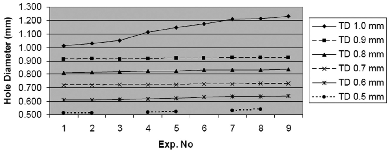
Drilled hole dimensional accuracy using different tool diameters. 90
From Figure 9, the experimental numbers increased with the diameters of the drilled holes. Most importantly, an increase in the TD caused a significant increase; deviation in the form of errors in the desired hole diameter. This was more evident at 0.6 and 0.8 mm TD immediately after experimental number 5, at most in 1.0 mm TD progressively. Dimensional errors ranging between 5% and 10% were recorded. 90 In summary, it has been reported that the surface roughness of a drilled hole depended on the hardness of the workpiece and drill, geometry of the drill, drilling parameters and machine rigidity. 5
Other associated problems
Abrao et al. 111 suggested in their review article that the cutting speed should be kept below 60 m/mi; due to the fact that high cutting speed values led to higher cutting temperatures, which caused composite matrix softening, followed by matrix cratering and thermal damage of its constituents, particularly the binders.
Fibre pull-out and uncut fibre (Figure 10) are separate relevant problems. Zitoune et al. 113 reported the significance of the correct choice of process parameters especially when drilling multi-material stack. Their experimental results depicted that the quality of drilled holes could be improved by proper selection of cutting parameters as the drilled hole circularity increased with feed rate: around Ra of 6 µm (at low feed rates) to 25 µm in CFRP. From drill wear test results, they showed that thrust force significantly increased to 90% in CFRP compared with 6% in aluminium after the first 30 holes were drilled. When the number of holes increased to 60, composite fibre pulled out and parts of the fibres remained uncut (Figure 10).
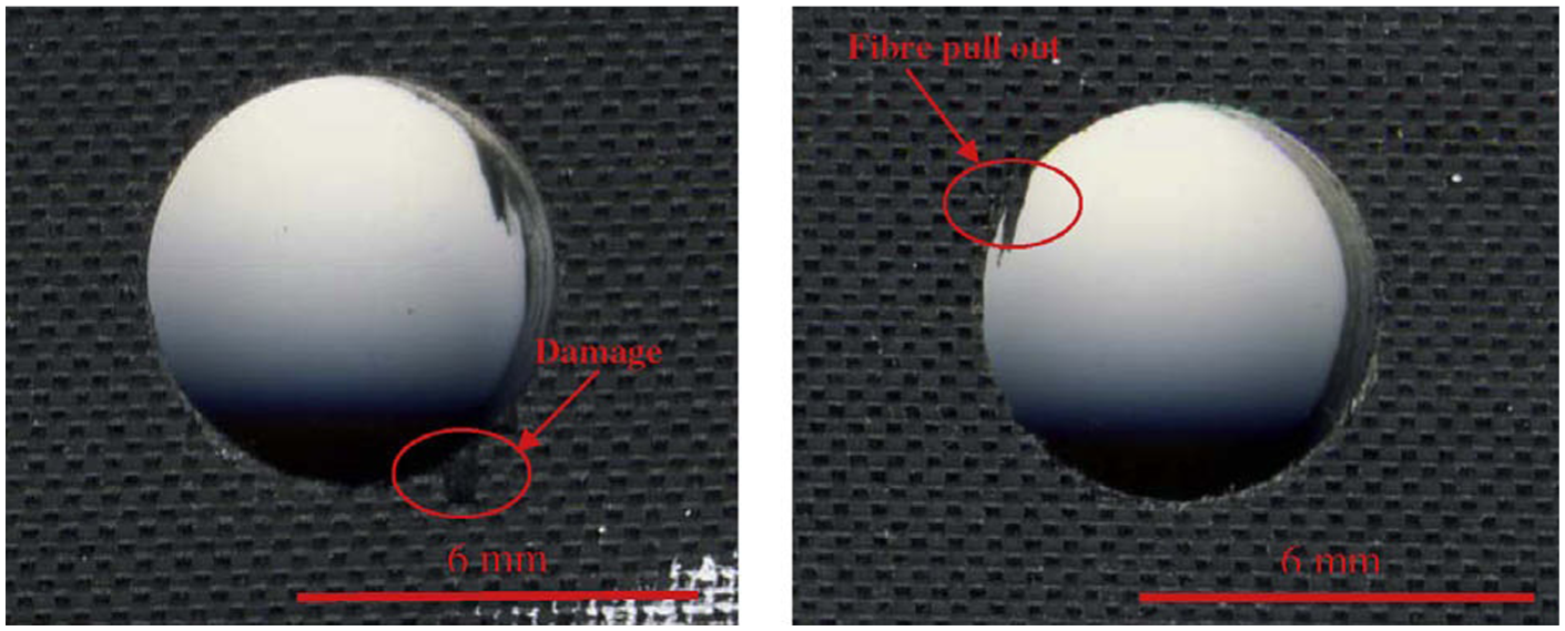
Fibre pull-out and fibre uncut defects at hole entry and exit. 113
Chip formation and separation
Composite fibre orientation determines chip formation during machining. The chip formed on the drill increased as the cutting speed increased during composite drilling. 88 FEA drilling model that showed chip formation at the exit surface has been developed by Min et al. 48 The model was used to simulate the formation of both crown and homogeneous chips which were formed at higher and lower feeds, respectively. They based the failure criterion governing the chip formation on the equivalent discrete element-plastic strain. Also, the same plastic failure criterion was used to model chip separation by Klocke et al. 114
Parametric design (input variables)
The drilling parameters are the machining variables and conditions that affect the entire drilling process. They are machine capacity and function-dependents. Among them are cutting force, thrust force, torque, feed rate, material removal rate (MRR), coolant flow resistance and cutting speed. It has been reported that thrust force and torque increased with the size of the drill bits. Also, an increase in feed rate caused an increase in both thrust force and torque, while both decreased with the spindle speed. 83 The effects of drill wear and composite thickness on thrust force and torque have been investigated using ‘one shot’ drill bit.44,115 They concluded that the thrust force increased with the number of drilled holes for twist drill bit, unlike torque. A decrease in composite thickness caused an increase in thrust force due to wear, while an increase in feed affected the thrust force causing an increase in the rate of the tool wear. Hence, thrust force and torque significantly depend on drill feed rate, bit, wear and composite thickness.
The experimental results of CFRP composite drilling using carbide, HSS and PCD drills conducted by Madhavan and Prabu 54 and Mohan et al. 66 revealed the effect of feed rates, drill geometry and cutting speeds on chip formation, delamination, surface roughness and cutting forces. They stated that feed rate increased with delamination factor and surface roughness. Chip formation increased with an increase in cutting force. Similarly, the variations in cutting forces with or without onset of delamination during the drilling operations have been studied by Chen 53 and concluded that the delamination-free drilling processes might be obtained by the proper selections of tool geometry and drilling parameters such as cutting force.
During drilling, thrust force is the applied force on the workpiece by the machine tool through speed and feed in downward direction. It is the plunging force of the drill bit unlike cutting force which is rotating force. Delamination effect, occurred principally at the drill exit in the composite materials, has been reported to be mainly caused by the thrust force.105,116 An optimisation of twist drill point geometries in order to minimise thrust and torque in drilling has been carried out by Paul et al., 16 using conical, racon and helical drill point geometries. Racon drill showed a marked reduction in thrust while the optimised helical drill reduced thrust by over 40% when compared with conical. Lazar and Xirouchakis 70 experimentally determined the axial and tangential cutting loads’ distribution by analysing the thrust on drilling CFRP composites with three different types of drills. It was shown that the maximum thrust forces occurred on the fibre plies in contact with the drill tip. Analysis of delamination in various drills, such as saw, candle stick, core and step drills, has been analytically and compressively carried out by Hocheng and Tsao. 51 They predicted the critical thrust force that caused the initiation of delamination mathematically. They concluded by comparing the results obtained with that of a twist drill for all the available drills and predicted the decrease in critical thrust for the different drills and the points at which they were reduced to the twist drill. Theoretical predictions of critical thrust force at the inception of delamination of different special drill bits have been carried out by Hocheng and Tsao 117 using experimental investigations. Their results on critical thrust forces were confirmed and agreed with both the analytical findings of critical thrust forces and industrial experiences that drill geometry has a significant effect on the thrust force, as supported by works of Madhavan and Prabu 54 and Wang et al. 62
Moreover, formulation of a detailed analysis for the critical thrust force ratio related to the peripheral drilling moment has been conducted by Tsao and Hocheng. 116 Special drill bits such as saw, core and candle stick were used for the composite drilling. It was concluded that the special drill bits possessed a lower critical thrust force at peripheral drilling moment than without peripheral moment. This indicated that at the exit of drill bit in the composite materials, the peripheral moment caused bigger delamination drilling-induced damage. Prediction of thrust force during all 100/10% SiC metal matrix composites’ (MMCs) drilling has been performed. 118 Both the experimental method and ABAQUS/Explicit FEA were used, with close agreement in their results. Drilling the typical MMCs with a low cutting speed and feed rate, for reduction in thrust force, was recommended.
Xiong et al. 9 used mapping method to develop 81 major mathematical equations in a new methodology for designing a curve-edged twist drill. They distributed the cutting angles along the tool cutting edge randomly. Their results were validated experimentally, and the drilling torque and the thrust force were compared. It showed that the new curve-edged drill reduced the drilling torque and thrust force by 28.5% and 24.6% on average, respectively. Nagaraja et al. 119 reported that an increase in spindle speed and feed rate led to an increase in torque, delamination and thrust force when drilling carbon fibre epoxy composite using HSS drill. They concluded that spindle speed has an insignificant effect on torque and thrust force.
Liu et al. 50 stated that feed rate had the greatest influence on drill wear, thrust force and delamination. 120 Low feed rate coupled with high cutting speed reduced delamination and prolonged drill life. 50 Research on the development of suitable models with intelligent control scheme in the machining of composite laminates has been carried out by Dharan and Won. 59 Drilling experiments were conducted using carbide-tipped twist drills on the composite material to obtain thrust force and torque responses for a wide range of feeds in high-rate drilling. Empirical expressions relating the thrust force and torque to the feed and drill diameter were obtained from the results of the experiment. Isbilir and Ghassemieh 109 declared vividly that the detailed understanding of the effects of higher feed rate on delamination and thrust force is essential before embark on its application. They concluded that step drill reduced torque and thrust force (delamination) when compared to twist drill at similar feed rate and speed.
MRR is another drilling parameter that determines the efficiency of a drill. A good designed drill should be able to evacuate chips easily and rapidly. In an attempt to determine the drilling process for carbon laminates, Sardiñas et al. 46 proposed a multi-objective optimisation of the drilling process. Two mutually contradictory objectives were optimised: MRR and delamination factor, which represented the productivity and characterised the superficial quality, respectively, as jointly contradictory objectives were optimised. An increase in cutting speed and feed led to an increase in MRR while delamination factor increased with a decrease in MRR.
During wet machining, the flow rate of coolant is imperative. Abele and Fujara 33 designed a drill geometry performance characteristic model and used it to obtain drill performance characteristics, numerical simulation of 3D FEA models and calculated coolant flow resistance. Their models also captured prediction of coolant flow and effects of coolant channel diameter and its surface roughness.
The cutting speed of a drill determines the rate of production of holes in composite materials. Cutting speed has less effect on delamination when compared with feed rate. 50 HSS drill supported a high cutting speed when compared with carbide (coated and uncoated types) and PCD. 54 Isbilir and Ghassemieh 121 stated that surface roughness and delamination damage reduced with an increase in cutting speed when drilling CFRP composite with multi-layer TiAlN/TiN PVD tungsten carbide tools. They concluded that drilling parameters influenced drilling outputs significantly. Gaitonde et al. 45 investigated process parametric effects on delamination during high-speed thin woven-ply CFRP composite drilling. Cutting speed, one of the process parameters considered, was used to analyse the delamination damage factor. Their investigations showed that the delamination tendency decreased with cutting speed and further suggested that combined low values of feed rate and point angle would reduce the damage. 99 Conversely, Sardiñas et al., 46 Davim and Reis 52 and Kilickap 44 studied delamination during conventional drilling of composite laminates and optimisation of cutting parameters using genetic algorithms, design experiments and Taguchi methods, respectively. They reported that delamination increased with cutting speed. Finally, high spindle speed as well as lower feed rate favoured delamination-free composite drilling. Thus, thrust force and delaminations go together and depend on other drilling parameters such as cutting speed, 44 feed rate (as illustrated in Figure 11), drill geometry and wear.20,50,67,99 From the 3D plot of Figure 11, the highest thrust force of more than 500 N was recorded at highest feed rate of 0.8 mm/rev and lowest cutting speed of 24 m/min. These results evidently implied that the thrust force of the drills increased as the feed rate increased, but decreased as the cutting force increased during CFRP composite (conventional) drilling. Also, a lowest feed rate of 0.1 mm/rev and thrust force of nearly 25 N were recorded at maximum cutting speed of 235 m/min.
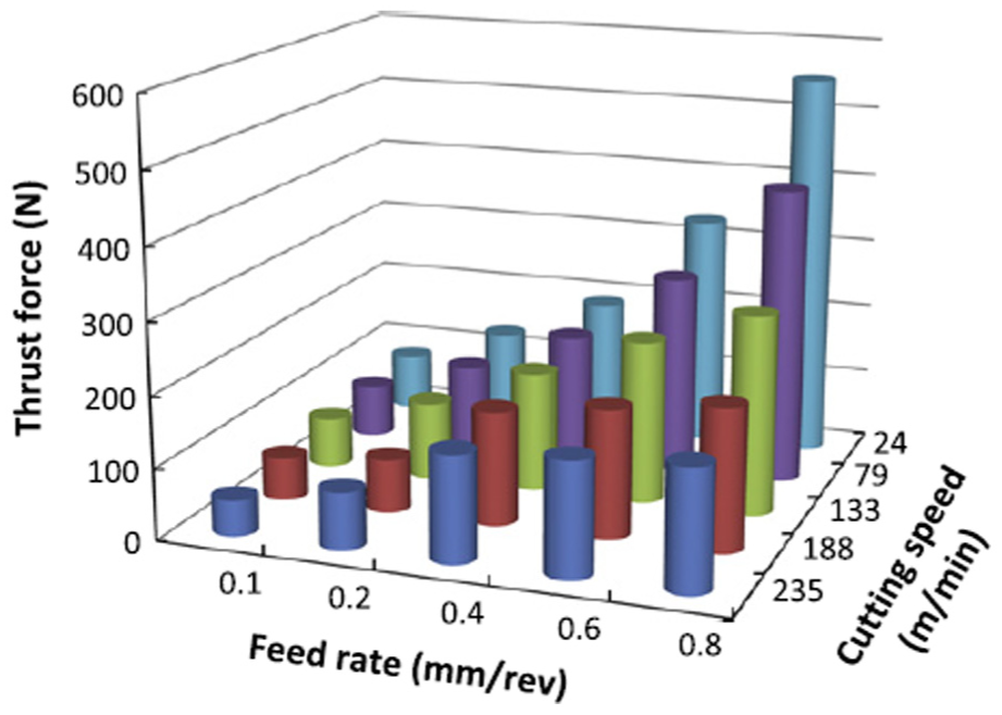
Parametric effect of cutting speed and feed rate on thrust force in CFRP composite drilling. 50
Conclusion
A highly efficient twist drill is the outcome of innovation and ingenuity. Recent advances in twist drill design with respect to composite drilling have been critically reviewed and presented. The following summary can be made:
HSS twist geometry is the most commonly used type of drilling tool due to its outstanding performance with regard to better chip removal, availability, mass production and cost-effectiveness.
The chisel edge, point and helical angles are the most important parts of twist drill design geometry.
The quality of drilled hole depends greatly on the drill geometry, design, materials and selected drilling parameters.
Delamination of composites and rapid tool wear are the main problems encountered when drilling CFRP accounting for drilling-induced damage as high as almost two-thirds of the total drilled products.
PCD provides good surface finish at high cutting speed and feed rate. Improved surface quality and dimensional accuracy of composite materials could be achieved using carbide especially coated types and PCD drills.
Good knowledge of drilling parameters, composite materials and well-designed drill geometry afford better opportunity of developing drills that will minimise delamination effect on the reinforced composites, tool wear and produce a high-quality drilled hole surface.
The drill design engineers and manufacturers will obtain a comprehensive understanding of the recent advances in twist drill design for fibre-reinforced composites drilling by going through this review article, with the intention of improving and optimising the efficiency of drills and solving challenges confronting composite drilling.
Footnotes
Appendix 1
Declaration of conflicting interests
The author(s) declared no potential conflicts of interest with respect to the research, authorship and/or publication of this article.
Funding
The author(s) disclosed receipt of the following financial support for the research, authorship, and/or publication of this article: The provision of part funding by the Niger-Delta Development Commission (NDDC) of Federal Government, Nigeria, under award number NDDC/DEHSS/2013PGFS/OND/3 is greatly acknowledged.