
Abstract
The purpose of this study is to evaluate the performance of new and reground cemented carbide twist drills considering the variation in the form of regrinding applied to a drill after it reaches its wear limit. The following variables were taken into account: coating material (uncoated, TiAlN and AlCrN) and recoating routine after regrinding (no recoating, recoating over existing coating and recoating after removal of the existing coating). The performance evaluation parameters were tool life, thrust force and torque. The results indicated that the performance of reground drills was generally inferior than that of new drills. Among the coated drills, only TiAlN-coated drills that were stripped (removal of the existing coating), reground and recoated (application of a new TiAlN coating) reached performance values approaching those of new drills. In most of the tests, the uncoated drills produced higher thrust forces and torque, underwent higher wear and had shorter tool lives.
Introduction
The majority of workpieces of any type or shape produced industrially have at least one hole, and only a very minor fraction come with the hole in the primary process to obtain the blank (e.g. casting or forging), according to Diniz et al. 1 There are various industrial machining processes for producing holes, each with its own characteristics and importance. Electrochemical machining, electron beam machining, conventional drilling, among others, are some of the machining processes employed in making holes in workpieces. Because it is the most competitive and flexible machining process, conventional drilling is the one most widely used for drilling holes. According to Tönshoff and Spintig, 2 33% of holes are produced by this process, representing approximately 25% of the time spent on all machining operations. The importance of this process is illustrated, for example, by the number of holes to be machined during the manufacture of engine blocks for automotive vehicles. According to Guesser, 3 four cylinder engines have approximately 75 holes while eight cylinder engines have 150 holes.
One of the problems in the drilling process is the removal of chips inside the hole. If chips are not formed so as to facilitate their removal, they may clog the holes, increasing the cutting torque and temperature and resulting in greater drill wear. Wear generally occurs by progressive loss of material, which causes changes in the tool’s shape. This occurs mainly in the more critical conditions and is strongly dependent on the combination of workpiece material, tool material and chip geometry.
According to the ISO 3685:1993 standard, 4 tool wear is the result of changes in the tool’s shape that occur during the cutting process, caused by the gradual loss of material or deformation. Machado et al. 5 offer a similar definition, but emphasize the distinction between damage, wear and deformation.
The time during which a cutting tool works effectively before being replaced or resharpened is called the “life of the cutting tool.” A criterion should be used to determine the end of tool life in order to ensure the economic viability of the production process. In this study, a maximum flank wear (VBBmax) was used as the end of tool life criterion.
Bakkal et al. 6 explain that during drilling, the chisel edge of the drill acts to extrude material (crushing the material) to the leading edges. The plastic deformation caused by the chisel edge influences the resistance to progression in the drilling process. Castro 7 points out that knowledge of the value of the thrust force is important to ensure that the axis of the machine can withstand the operation, and Teixeira 8 considers this as a good indicator of machinability. Figure 1 illustrates the directions of the machining force components, including the thrust force (Ff) in the drilling process.
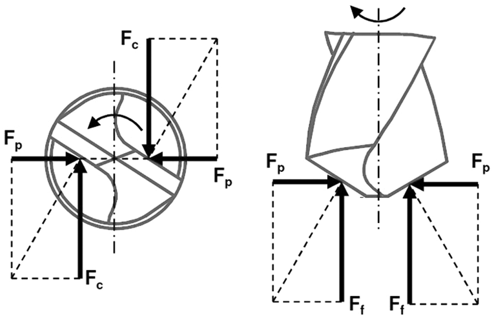
Forces acting on the principal cutting edge. 9
When a drill reaches its end of life, regrinding is an alternative to discarding the tool. However, doubts remain about the quality of the performance of reground drills. Regrinding twist drills not only reduce the consumption of raw material but also offer a solution for the reuse of worn drills. According to Ostronoff, 10 regrinding a drill just once already provides a favorable cost–benefit.
Although the literature lacks reliable data about the performance of reground drills, shop floor information obtained by the authors indicates an average loss of 20% in life compared with newly coated tools. These facts motivated this study, whose main objective is to compare the performance of step drills: uncoated and carbide-coated (TiAlN and AlCrN) drills and new and reground drills. The drill regrinding routine was also varied. The performance evaluation parameters were wear, thrust force and torque.
Experimental method and materials
Machined material
The material of the experimental test specimens for the comparison of drill life was DIN 19MnCr5G steel. This material is used in the manufacture of cylindrical crown gear drives for automobiles (Figure 2). Table 1 describes the chemical composition of this material, whose average hardness is 151 HV.
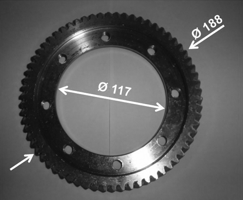
Cylindrical crown used in the experiments, showing inner and outer diameters in millimeter.
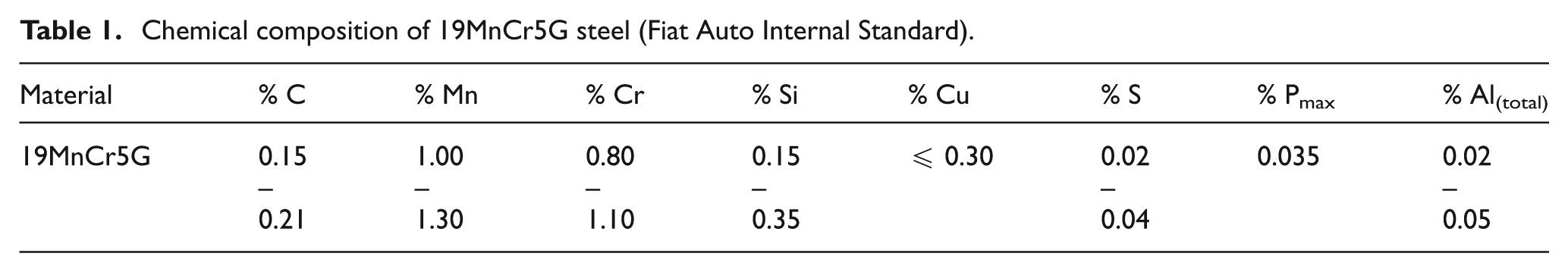
Chemical composition of 19MnCr5G steel (Fiat Auto Internal Standard).
Cutting tools
The cutting tools used in the experimental tests were step drills of grade P20 carbide, with clockwise cut and two main cutting edges with designation 2D9, 8/14 xL10, 5/45, manufactured by OSG Sulamericana de Ferramentas Ltda. Uncoated drills and physical vapor deposition (PVD) TiAlN- or AlCrN-coated drills were used, whose dimensional details are depicted in Figure 3.
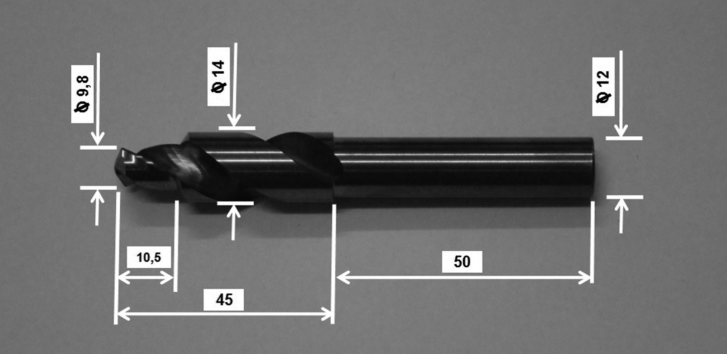
Step drill used in the experiments.
Three different routines were used in the tests with TiAlN-coated reground drills: (1) without recoating, (2) coating applied over the existing coating and (3) coating applied after removal of the existing coating. Coatings and recoatings were produced by Oerlikon Balzers Metal Coating Ltda. The coatings, recoating and coating removal were performed according to the company’s industrial routines, but the authors were not given access to information or details about these processes. The process of regrinding them was the same used to manufacture a new tool. The PVD recoating process was also the same used to coat a new tool. Only the first routine—without recoating—was used in the tests with reground AlCrN-coated drills.
Machine tool
Two machine tools were used in the experiments, one for tool wear tests and the other for thrust force and torque tests. The machine tool used in the tool life tests was a computer numerical control (CNC) Famar Tandem 260 machining center with a main motor of 75 kW, belonging to the production line of a large auto manufacturer (Figure 4(a)).
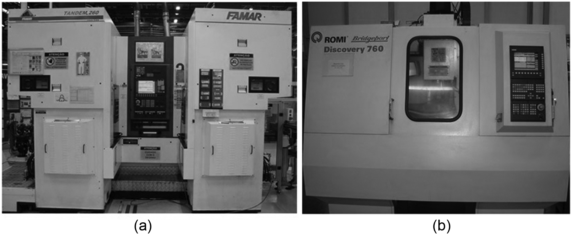
(a) Famar Tandem 260 machining center and (b) Romi/Discovery 760 machining center.
This machine produces four holes simultaneously in each operation and each drill makes two holes in each workpiece (cylindrical crown). The operation was performed in the vertical direction with a downward movement of the workpiece. Figure 5 shows the drills assembled inside the machine. Note the four thread tapping tools that make threads immediately after the holes have been opened. However, this operation is not the object of the present study.
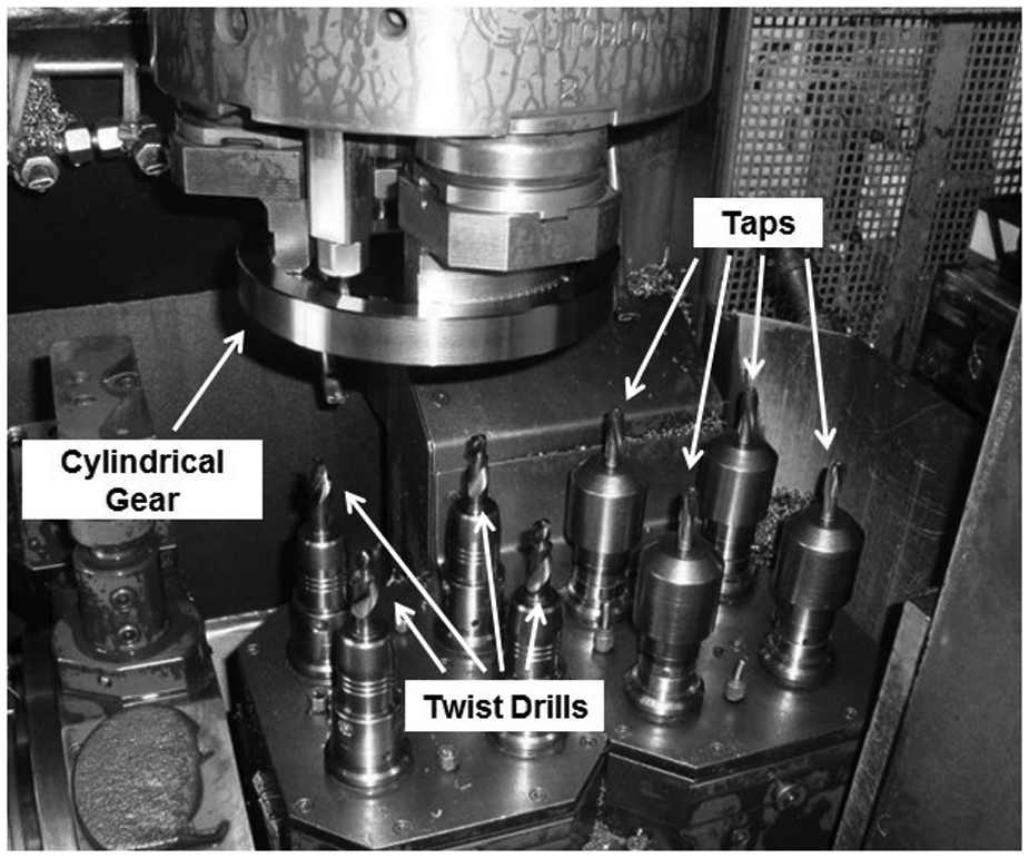
Internal mounting of drills in the Famar Tandem 260 machining center.
Figure 6 shows the dimensions of the hole. As can be seen, the 14-mm-diameter drill is used only to countersink the hole, facilitating the entry of the tapping tool, which will produce the thread in the cylindrical crown.
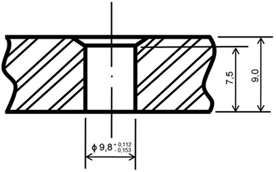
Dimensions of the hole.
The thrust force and torque tests were performed in the laboratory in a Bridgeport-Romi Discovery 760 vertical CNC machining center, with a Siemens 810 numerical control with 9 kW of power. This machine (Figure 4(b)) is manufactured by Indústrias Romi S.A. (Brazil) and has a maximum spindle speed of 10,000 r/min.
Three equally spaced fasteners were used to ensure optimal fixation of the cylindrical crown during the thrust force and torque tests (Figure 7). This type of fixation reduces vibration during machining, which is important for data acquisition.
Fixation of the cylindrical crown.
Cutting fluid
The tool wear tests were performed in an industrial setting while the thrust force and torque tests were carried out in the laboratory. In all the tests, the cutting fluid was applied in the conventional manner at a flow rate of 730 L/h distributed by three nozzles, as illustrated in Figure 8. The fluid was microemulsion of EcoCool RE 42 W semi-synthetic cutting fluid manufactured by Fuchs do Brasil S.A. (Brazil) and applied at a concentration of 6%.
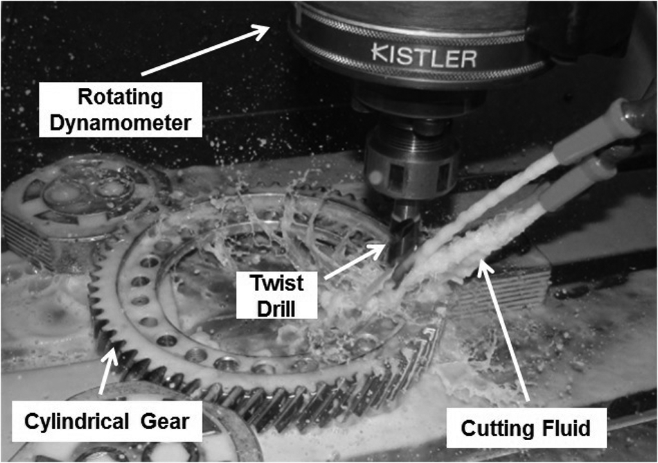
External application of cutting fluid during drilling.
Experimental methodology
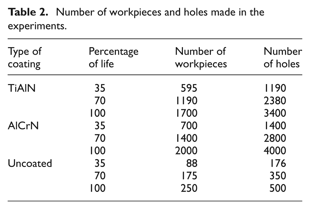
The tests were performed using the following strategy. The tool wear tests were carried out on an automotive production line. Based on a maximum flank wear (VBBmax) of 0.3 mm, the specific number of workpieces to be machined with each drill (both new and reground) was defined in pretests to evaluate the drill’s wear. The numbers were 250 workpieces (or 500 holes, since each drill made two holes in each workpiece) for uncoated drills, 1700 workpieces (or 3400 holes) for TiAlN-coated drills and 2000 workpieces (or 4000 holes) for AlCrN-coated drills. In these wear tests, four drills were tested simultaneously (see Figure 5), thereby providing four replicates to calculate the statistical mean.
The thrust force and torque tests were performed in the laboratory during the drills’ various stages of life. Drills used on the production line were tested at the following percentages of life: 0%, 35%, 70% and 100%. Table 2 lists the number of workpieces and holes drilled at each of these percentages of drill life. The evolution of wear during these stages of the drills’ lives was analyzed using an OLYMPUS SZ-6145TR optical microscope and a Hitachi TM 3000 scanning electron microscope (SEM). An artificial external lighting system (Figure 9) and image capture and analysis software (Image-Pro Express) were used to measure wear under the microscope.
Number of workpieces and holes made in the experiments.
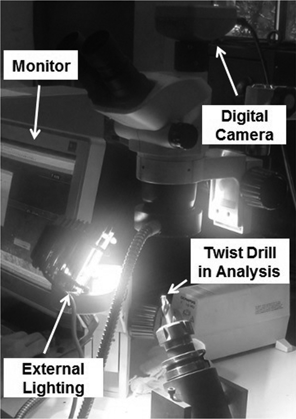
Drill positioned in the optical microscope to measure its wear.
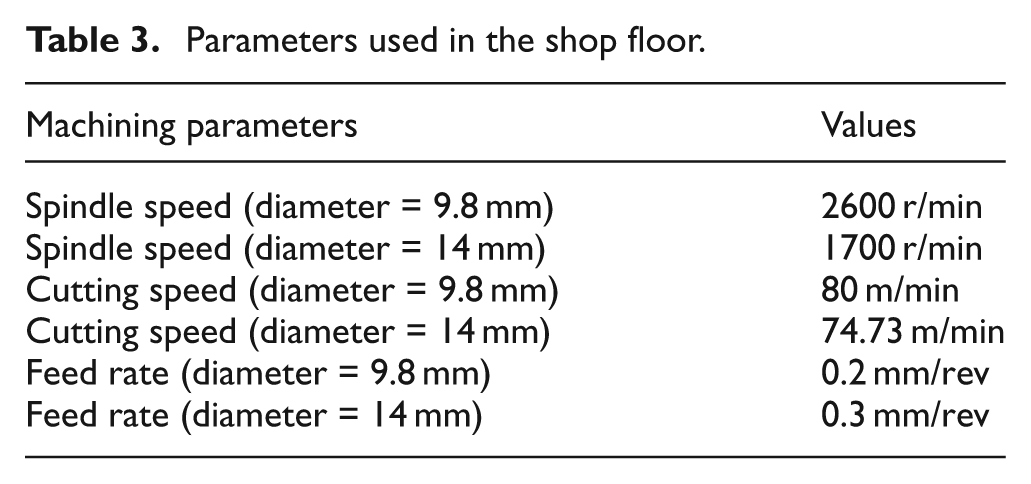
The same cutting parameters were applied in the industrial wear tests and the thrust force and torque tests performed in the laboratory (Table 3). However, different machining parameters were employed whenever the larger diameter of the step drill was in contact with the workpiece.
Parameters used in the shop floor.
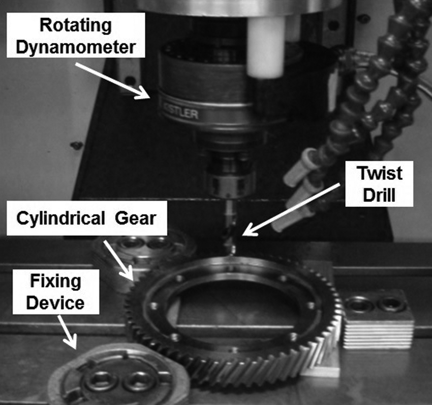
A model 9123 rotating dynamometer manufactured by the Swiss company Kistler Instrumente AG was attached to the spindle of the machine tool for the thrust force and torque tests. After the torque and thrust force signals were decomposed, they were amplified and conditioned using a model 5223B2 multichannel signal conditioner manufactured by the same company. The system was calibrated to measure thrust force and torque, with deviations of less than 1% within the measuring range of 0–2000 N and 0–2000 N cm, respectively. An acquisition frequency of 0.5 kHz and an acquisition time of 15 s were established for these two parameters.
In general, three holes were made by each drill, and the signals were acquired during the machining process, from the entry to the exit of the hole in the cylindrical crown. Figure 10 shows the thrust force signals during a complete drilling process of a hole. The graph represents the time the step drill is cutting. As it has two diameters (step drill), the first pick represents the cut performed by the smaller diameter of 9.8 mm (approximately between 3 and 5 s). After that the tool is not cutting because it has overpassed the thickness of the workpiece (and the force drops—exit (diameter of 9.8 mm)). The drill continues to move toward feed direction without cutting until the second diameter of the drill (14 mm) starts machining (at approximately 11.5 s). The cutting time of this second diameter is very fast. It only countersinks the hole being machined and the force signals generated were not considered in this study. Two thousand points were recorded in the cutting interval for the 9.8 mm diameter (within the measuring zone). The mean and dispersion were calculated from the three replicates to ensure the reliability of the measurements.
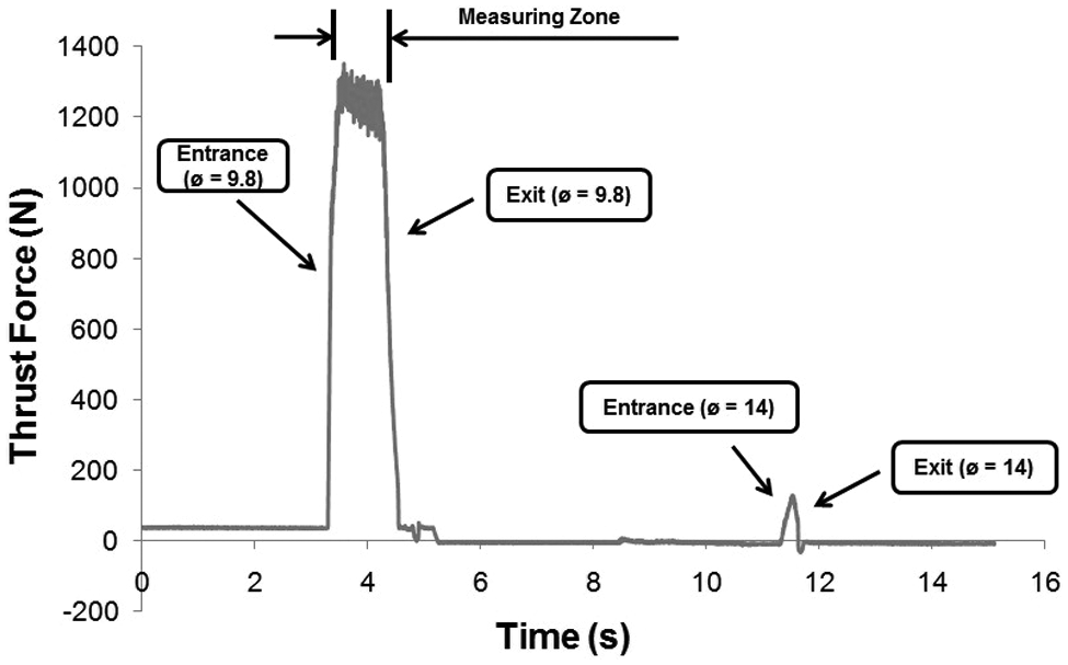
Typical graph of measured thrust force.
Experimental results and discussion
Tool wear
TiAlN-coated drills
Figure 11 shows the evolution of the maximum flank wear of four (equals) new TiAlN-coated drills (test and replicas). Note the good repeatability of the wear results during the life of the four drills. Each point represents the value of maximum flank wear at the edges of the drill. The reground drills and AlCrN-coated drills displayed a similar behavior.
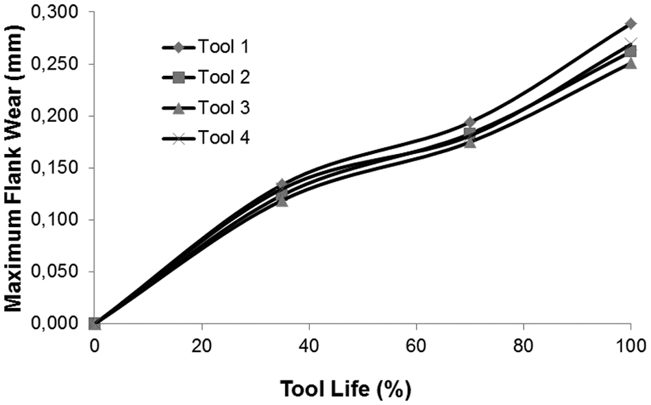
Evolution of maximum flank wear of new TiAlN-coated drills.
Figure 12 compares the evolution of wear of new and reground TiAlN-coated drills. The new drills showed the better performance (less wear).
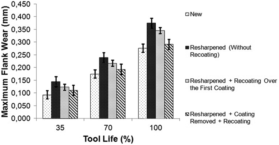
Comparison of wear during the life of new and reground TiAlN-coated drills.
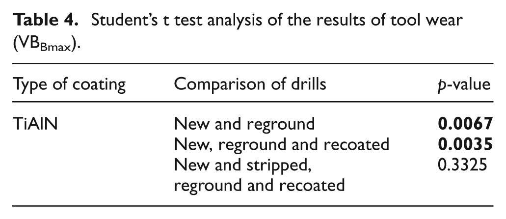
Although the graphics of Figure 12 indicates differences on the average values of tool wear, to compare new and reground drills, statistical tools were used to ensure reliability. Student’s t test of the average maximum flank wear (VBBmax) at the end of life of reground and new tools (individual comparisons considering the new drill as level +1) described in Table 4 (for a reliability of 95% and 5% significance level) indicates that only the tools that were first stripped, then reground and then recoated showed no statistically significant differences from the new drills. Drills that were not recoated and drill recoated without first stripping off the existing coating showed statistically significant differences from the new tools (p-value < 0.05).
Student’s t test analysis of the results of tool wear (VBBmax).
The wear values of tools that were stripped (removal of the existing coating), reground and recoated (application of new TiAlN coating) were similar to those of new drills, with an average increase of 11.74% (calculated considering comparisons throughout drill life, that is, 35%, 70% and 100% of life). However, considering only at the end of life (100% of life), the percentage increase was only 5.38%. The drills that were reground but not recoated showed the worst results. This behavior showed the ability of recoating to increase the tools’ wear resistance. On non-recoated drills, the main flank face areas showed exposed substrates, which accelerate wear.
The reground drills that were recoated over the existing coating showed the second worst performance. This routine was less effective than that of stripping, regrinding and recoating. In the latter case, there was less adhesion of workpiece material on the worn area of the drill. The SEM micrographs in Figure 13 depict the cutting edges that showed the highest wear rates at the end of life. It was observed that after drilling 1700 workpieces (3400 holes), only the drills that were reground and those reground and recoated over the existing coating showed edge chipping. New drills and stripped, reground and recoated drills showed uniform flank wear.
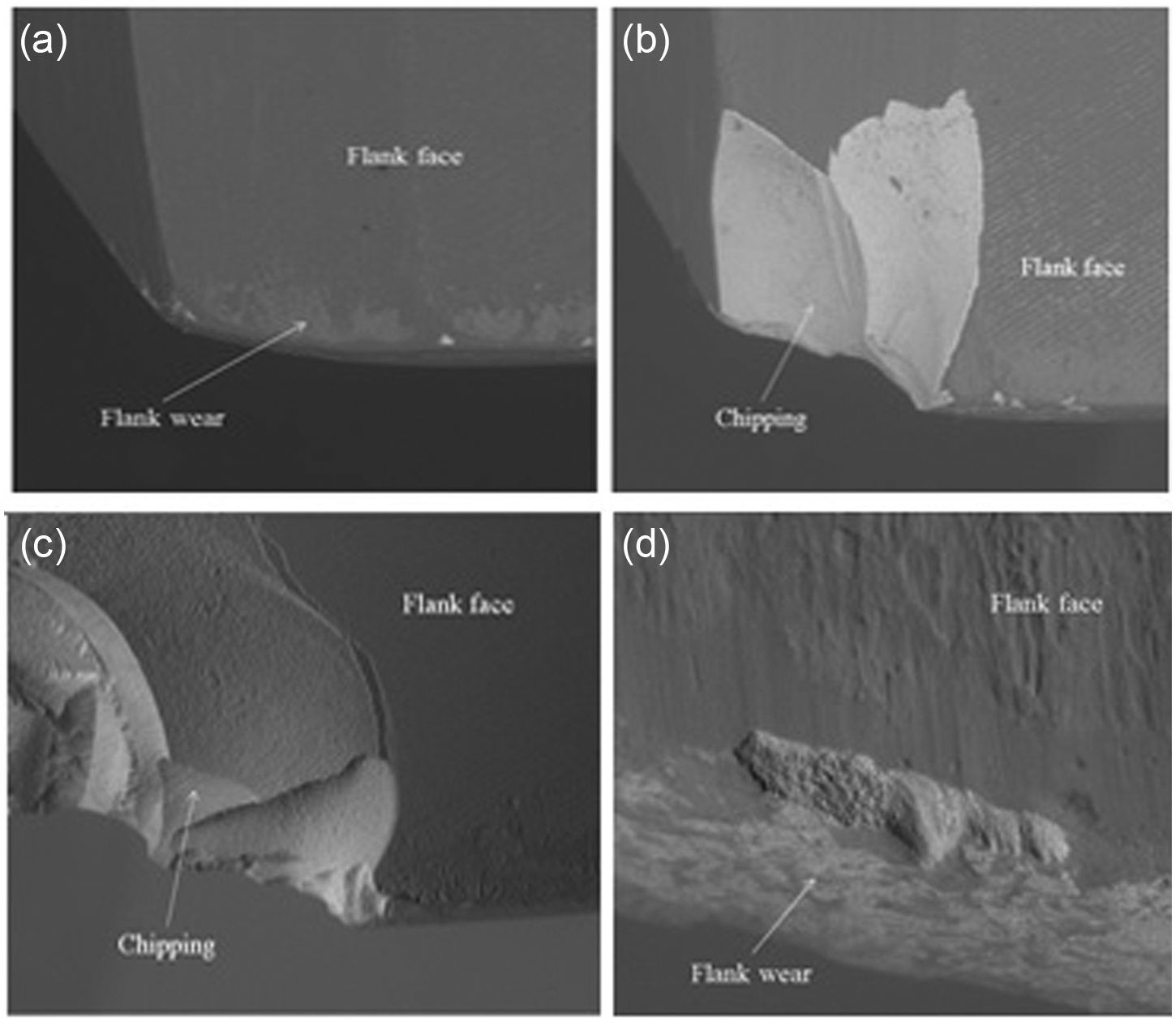
Analysis of wear of TiAlN-coated drills: (a) new (100×), (b) reground (100×), (c) reground and recoated (100×) and (d) stripped, reground and recoated (800×).
AlCrN-coated drills
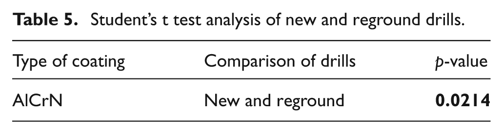
Figure 14 shows the evolution of the average maximum flank wear (VBBmax) during the life of new AlCrN drills and reground AlCrN-coated drills. The results of Student’s t test analysis with 95% reliability and 5% significance showed a statistically significant difference in the wear presented by reground and new drills (Table 5).
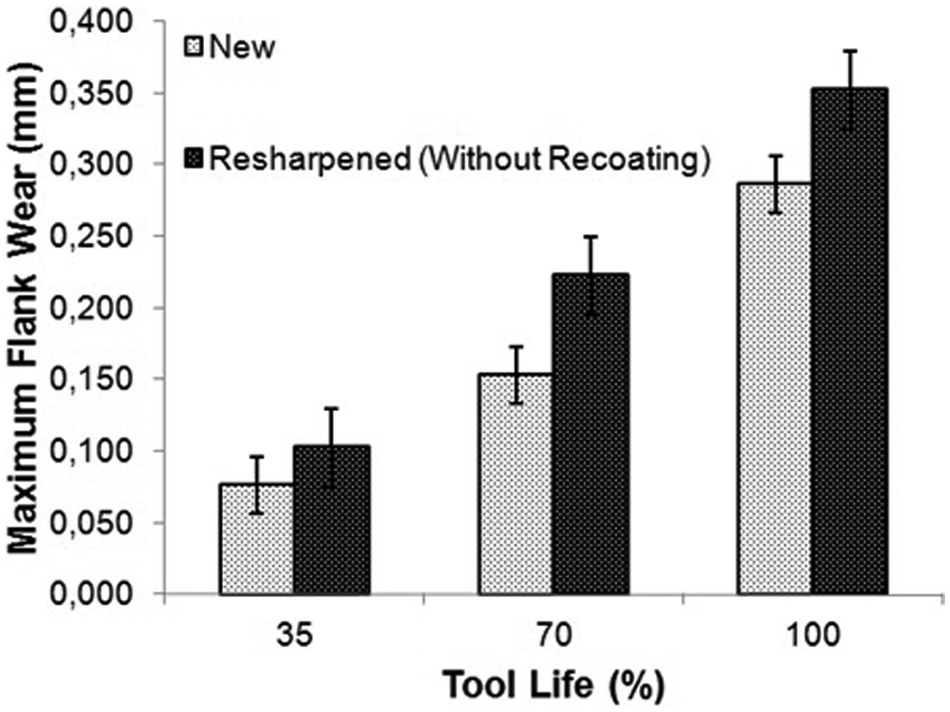
Comparison of new and reground AlCrN-coated drills.
Student’s t test analysis of new and reground drills.
Comparisons were made of the TiAlN and AlCrN coatings during pretests to determine the number of workpieces to be subjected to wear tests. The higher wear resistance of the AlCrN coating than that of the TiAlN coating on both new and reground drills was evident from the number of workpieces machined in the end of life wear tests. As can be seen in Table 2, the AlCrN-coated tools drilled 2000 workpieces (4000 holes) while the TiAlN-coated ones drilled 1700 workpieces (3400 holes) before reaching the end of life.
The reground drills showed higher wear than the new drills (average of 45.15%, based on comparisons during the life of the drills, that is, 35%, 70% and 100% of life). However, considering only the end of life (100% of life time), the percentage increase was only 22.91%. These results indicate that the new area formed by regrinding without coating suffered higher friction than the new drill. Regions of higher friction favor higher temperatures and adhesion of material to the tool’s surface. This adhesion probably caused greater wear due to the increased temperature at the tool/workpiece interface. Figures 15 and 16 depict SEM micrographs of the cutting edges that showed the highest wear at their end of life. The wear mechanism acting on the new drills was probably adhesion, while diffusion wear was more evident on the reground drills.

Analysis of wear of a new AlCrN-coated drill: (a) 60×, (b) 600× (detail “X”) and (c) 2000× (detail “Y”).
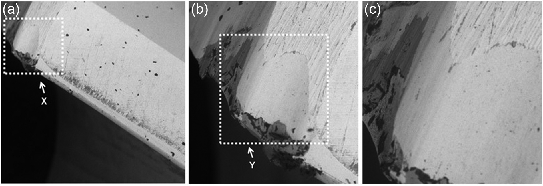
Analysis of wear of reground AlCrN-coated drills: (a) 40×, (b) 100× (detail “X”) and (c) 200× (detail “Y”).
Thrust force and torque
TiAlN-coated drills
An analysis of the thrust forces obtained during experiments showed good repeatability, as indicated in Figure 17 (tools 1–4 are test and replicas). This repeatability was also observed in the reground drills and AlCrN-coated drills. During the life of the drills, this repeatability also indicates the high rigidity of the machine tool used in the experiments.
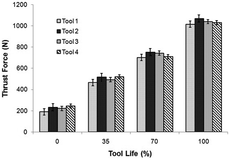
Repeatability of the thrust force results during the life of new TiAlN-coated drills.
There was also a clear increase in the thrust forces as the drills became worn. Figure 18 shows the evolution of the thrust force of new and reground TiAlN-coated drills. In every case (new and reground drills), there was a direct correlation between the percentage of tool life and thrust force. This behavior was also observed by Godoy, 11 Khabeery, 12 Kudla, 13 Muthukrishna and Sujatha 14 and Schroeter and Weingaertner. 15 New drills required lower thrust forces than reground drills.
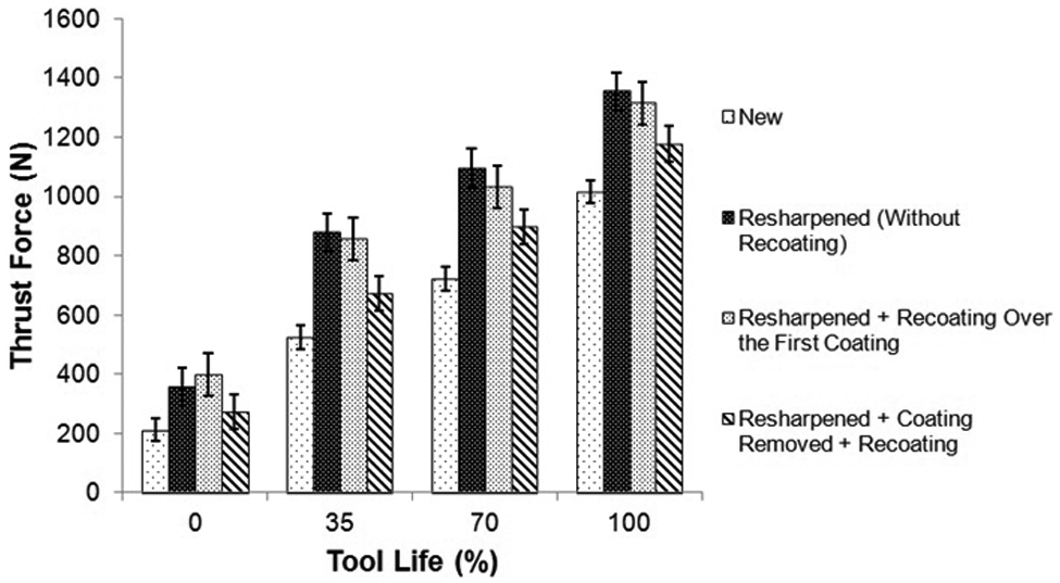
Comparison of thrust force during the tool life of new and reground TiAlN-coated drills.
The stripped (removal of the coating), reground and recoated (application of a new TiAlN coating) drills reached thrust forces closest to that of new drills, showing an average increase of 24.56% (calculated based on comparisons during the life of the drill, that is, 0%, 35%, 70% and 100% of life). However, comparing only at the beginning of life—the condition that eliminates the influence of wear, the average percentage increase was 29.45%. Like in the case of wear, the drills that were stripped, reground and recoated exhibited the best thrust force performance among the reground drills. Table 6 shows the evolution of the percentage increase of thrust force in relation to new TiAlN-coated drills.
Average percentage increase in thrust force throughout the life of reground drills compared with new drills—TiAlN coating.
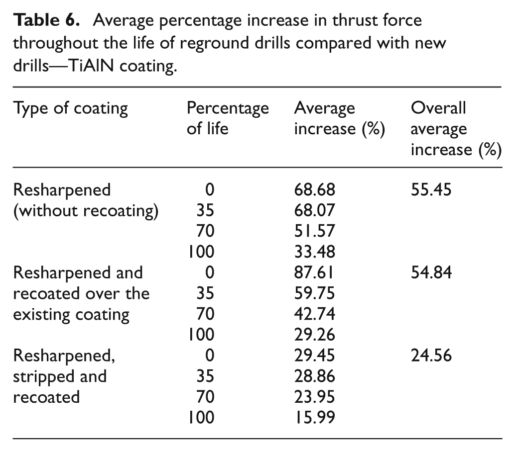
As the drill becomes worn, the percentage increase in thrust force declines slightly. This decline may be due to the fact that the wear of reground drills approaches that of new drills.
Figure 19 compares the evolution of the torque of new drills and drills reground by different routines. As in the case of the thrust force (Figure 15), the torque of the stripped, reground and recoated drills was closest to that obtained with the new drills, showing an average increase of 34.99% (calculated based on comparisons during the life of the drill, that is, 0%, 35%, 70% and 100% of life). However, comparing only at the beginning of life, the average percentage increase was 45.79% (see Table 7).
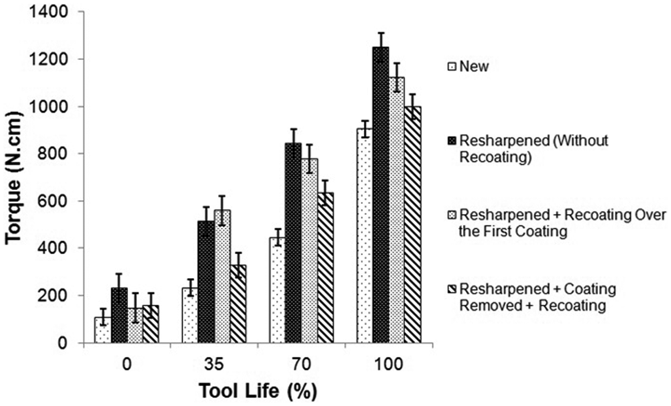
Comparison of the torque along the tool life of new and reground TiAlN-coated drills.
Average percentage increase in torque throughout the life of reground drills compared with new drills—TiAlN coating.
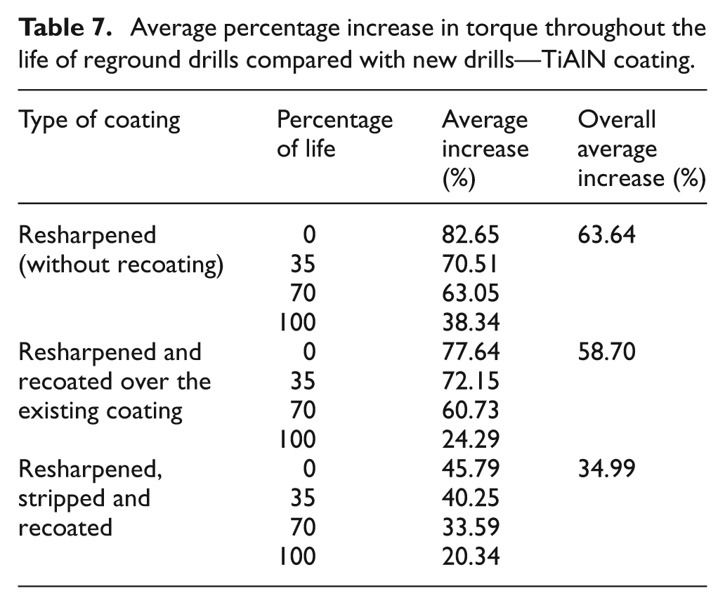
The drills that were only reground exhibited much poorer performance. These tools had an unprotected flank surface (uncoated), which greatly increased the friction between the workpiece and the drill, thus favoring higher machining forces and, consequently, of torque, due to the greater adhesion through contact with the workpiece. In a comparison that did not take into account the effect of wear, that is, at the beginning of life (0% life), the new drill showed the lowest average torque, while the stripped, reground and recoated drill showed the next lowest (45.79% higher than the new drill), followed by the reground and recoated drill (77.64% higher than the new drill) and finally the reground drill without recoating (82.65% higher than the new drill).
AlCrN-coated drills
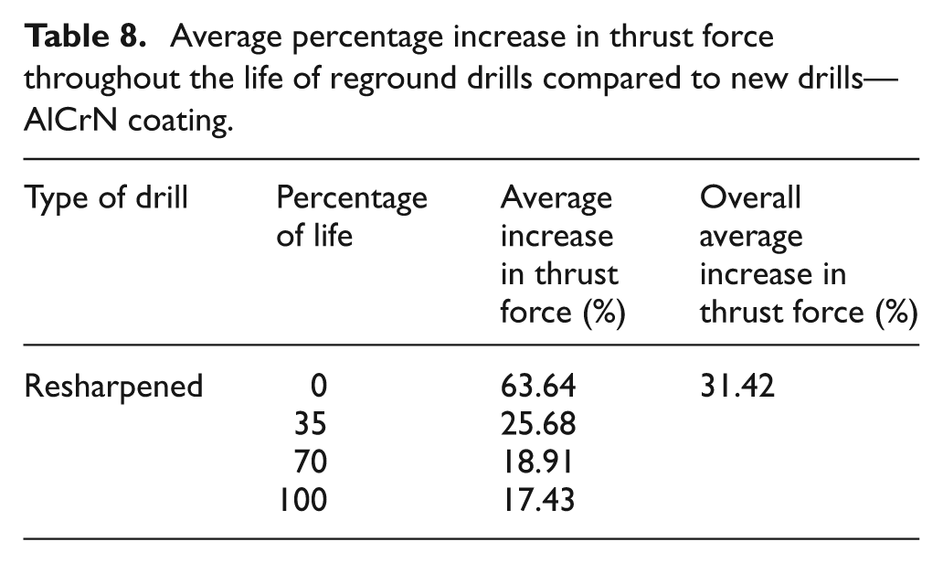
Figure 20 shows the thrust force and torque of new and reground AlCrN-coated drills. Like the TiAlN-coated drills, the thrust force of AlCrN-coated drills also increased during their life due to increasing wear, as shown in Figure 20(a). The reground drills showed higher thrust forces than the new drills, with an average increase of 31.42% (calculated based on comparisons during the life of the drill, that is, 0%, 35%, 70% and 100% of life). However, when comparing only at the beginning of life, the average percentage increase was 63.64% (Table 8).
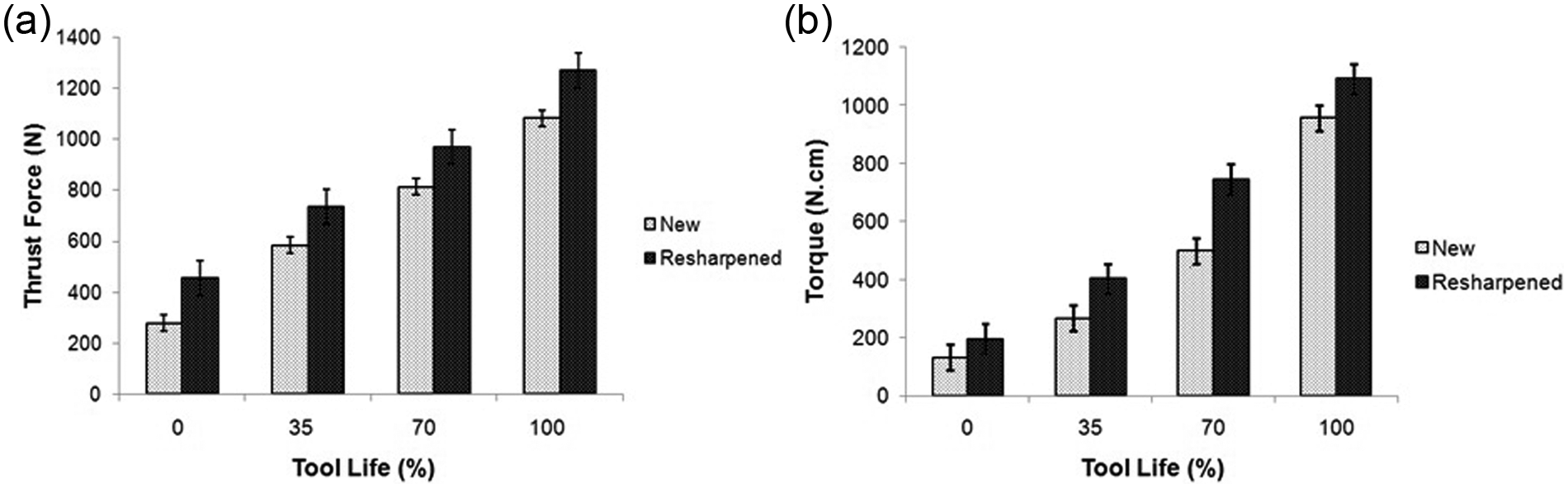
(a) Thrust force and (b) torque of new and reground AlCrN-coated drills.
Average percentage increase in thrust force throughout the life of reground drills compared to new drills—AlCrN coating.
As the tools approached their end of life (100% of life), the difference in the thrust forces of new and reground drills diminished. This tendency is explained by the fact that the maximum flank wear (VBBmax) showed the same behavior.
Figure 20(b) illustrates the evolution in torque of new and reground AlCrN-coated drills. The AlCrN-coated drills also showed increasing torque along their life in response to increasing wear.
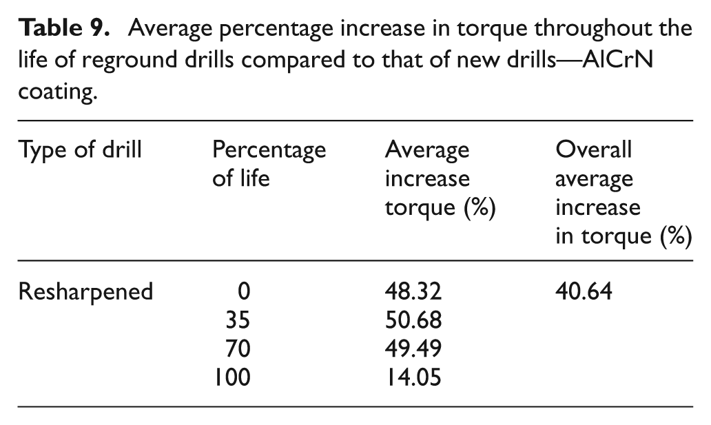
Table 9 shows the percentage increase in the average torque throughout the life of reground drills compared to that of new drills. The reground drills showed higher torque than the new drills, with an average increase of 40.64% (calculated based on comparison during the life of drill, that is, 0%, 35%, 70% and 100% of life). However, comparing only at the beginning of life, the average percentage increase was only 48.32%.
Average percentage increase in torque throughout the life of reground drills compared to that of new drills—AlCrN coating.
Comparison of coatings
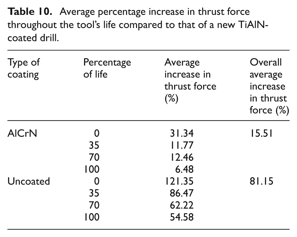
Figure 21 illustrates the influence of coating on thrust force and torque during tool life. The uncoated drills showed higher thrust force and torque than the TiAlN-coated drills (on average 81.15% and 74.44%, respectively). The same applies to AlCrN-coated tools, but in smaller proportions (on average 15.51% and 13.71%, respectively). Coatings reduce the adhesion of workpiece material to the tool, thus reducing the chip–workpiece–tool contact area and the machining forces. 16 The values in Figure 21 correspond to new drills. Coldwell 17 and Harris et al. 18 claim that high values of friction found in uncoated drills can contribute to the occurrence of wear mechanisms such as adhesion and abrasion, which directly influence tool wear, and hence, machining forces. The coating probably increased lubricity at the chip/tool interface. According to Ferraresi, 19 Khabeery 12 and Stemmer, 20 there is a greater tendency for cutting forces to increase due to the increased wear of the drill’s cutting edges when approaches its end of life.12,19 –21 Tables 10 and 11 describe the average percentage increase in thrust force and torque, respectively, during the life of a new AlCrN-coated drill and a new uncoated drill in relation to a new TiAlN-coated drill.
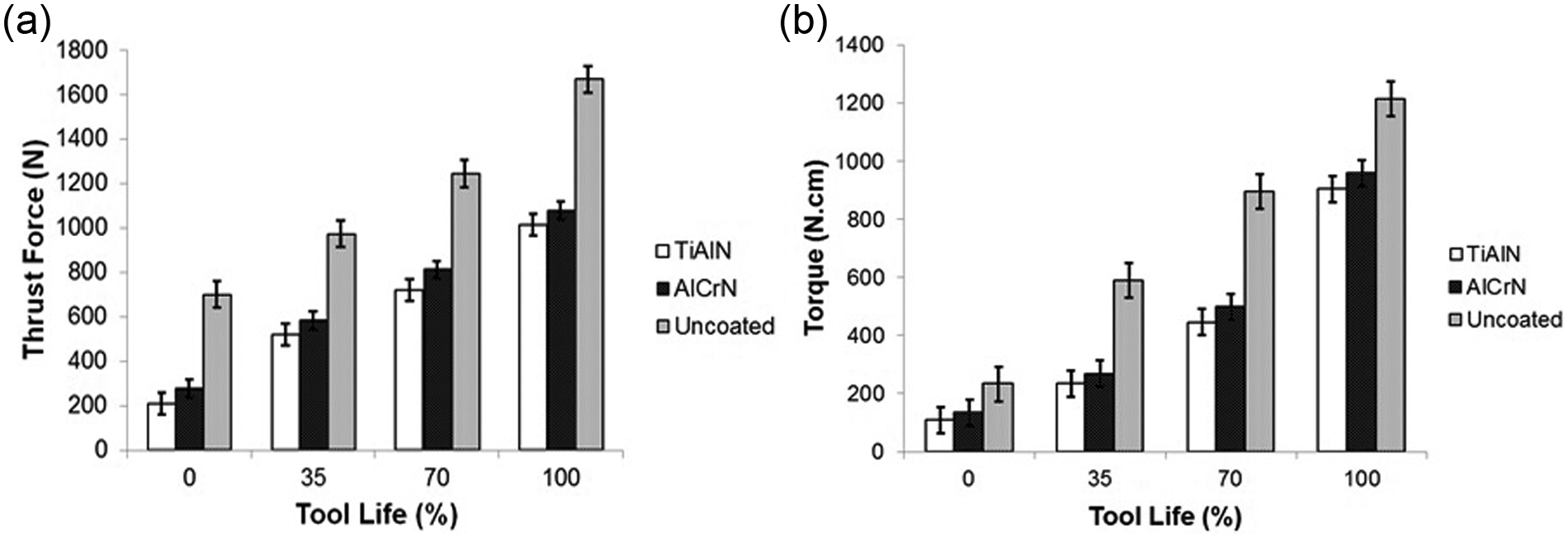
Comparison of types of coating: (a) thrust force and (b) torque.
Average percentage increase in thrust force throughout the tool’s life compared to that of a new TiAlN-coated drill.
Average percentage increase in torque throughout the tool’s life compared to that of a new TiAlN-coated drill.
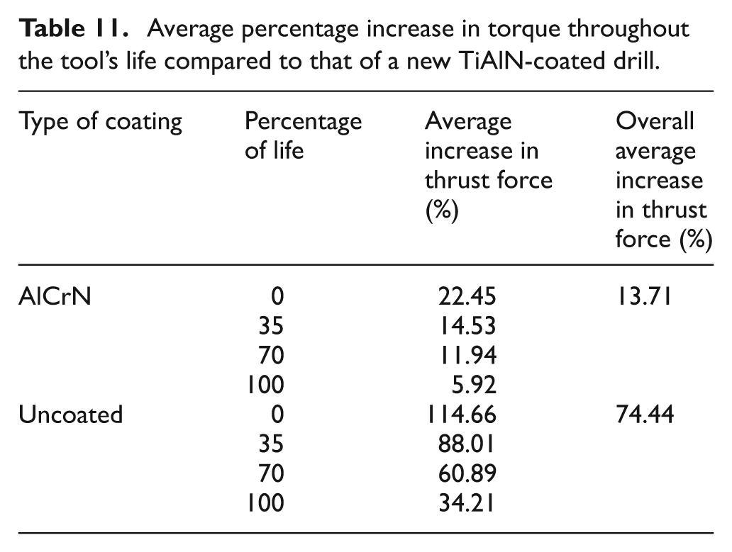
In Tables 10 and 11 and Figure 21, the thrust force and torque of all the tested drills showed a tendency of augmenting during their life. The increase in these variables is attributed to the drill’s increasing wear along its life. In their experiments, Castro, 7 Chen and Liao 22 and Wang 23 demonstrated that both thrust force and torque increased with the progression of wear. In the two parameters (thrust force and torque), the average increase in relation to new drills declined when the drills approached their end of life (100% of life).
Comparison of the treatments
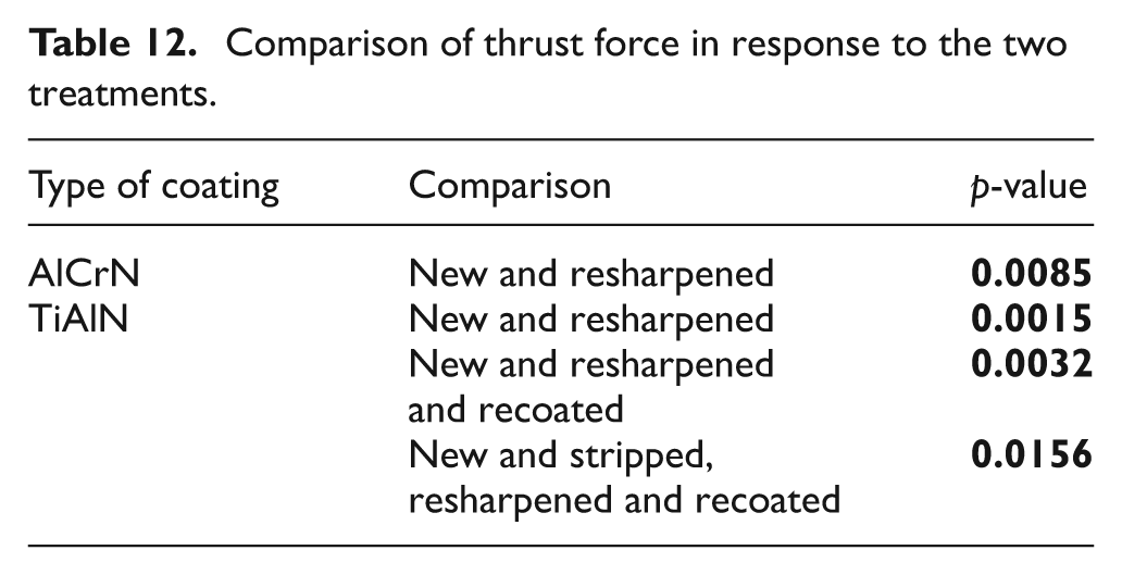
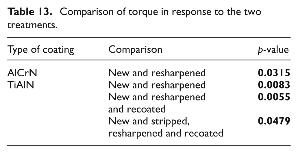
To compare new and reground drills, statistical tools were used to ensure reliability. The statistical tool used Student’s t test for paired comparisons of the results, considering 95% of confidence index and 5% of level of significance. They were applied to evaluate the thrust force and torque performance of the two coatings, respectively. The p-value < 0.05 indicates that the results obtained with all the tested drills differ statistically. Tables 12 and 13 present only the pairs of tools that differ significantly (p-values < 0.05). Reground drills showed higher thrust force and torque values than new drills. Of the two tested coatings, TiAlN showed slightly lower thrust force and torque values than AlCrN, although the confidence interval did not support this observation. However, this tendency was visible throughout the life of the drills, including new drills with 0% of wear, indicating that from the standpoint of thrust force and torque, the TiAlN coating is more suitable for machining DIN 10MnCr5 steel.
Comparison of thrust force in response to the two treatments.
Comparison of torque in response to the two treatments.
Conclusion
The results presented allow the following conclusions to be drawn:
Reground drills underwent higher wear (on average 33.85% more, considering all the tested drills) than new drills.
Among the TiAlN-coated drills, the ones that were stripped (removal of the existing coating), reground and recoated (application of a new TiAlN coating) reached the closest wear values to those of new drills (on average 11.74% more wear, calculated based on comparisons during the life of drills, that is, 0%, 35%, 70% and 100% of life). However, comparing only in the end of life, the average percentage increase was only 5.38%. Analyses of variance with 95% reliability indicated that these differences were not statistically significant. This indicates that removing the existing coating before recoating is the best routine to be applied in practice.
Among the AlCrN-coated drills, the reground drills showed higher wear than new drills (on average 45.15% higher, calculated based on comparisons during the life of the drills, that is, 0%, 35%, 70% and 100% of life). However, comparing only in the end of life, the average percentage increase was only 22.91%, which in this case was statistically significant.
The reground drills showed a significant increase in thrust force and torque values when compared with new drills (on average 29.13% and 32.04%, respectively).
The TiAlN-coated drills that were stripped (coating removed), reground and recoated (application of a new TiAlN coating) achieved thrust force and torque values closest to those of the new drill with the same coating (on average 24.56% and 34.99%, respectively, calculated based on comparisons during the life of the drills, that is, 0%, 35%, 70% and 100% of life. However, comparing only at the beginning of life, the average percentage increases were 29.45% and 45.79%, respectively).
Among the AlCrN-coated drills, the reground tools showed higher thrust force and torque values than new drills (an increase of 31.42% and 40.64%, respectively, calculated based on comparisons during the life of the drills, that is, 0%, 35%, 70% and 100% of life. However, comparing only at the beginning of life, the average percentage increases were 63.64% and 48.32%, respectively).
The uncoated drills showed higher thrust force and torque than TiAlN-coated drills (average increases of 81.15% and 74.44%, respectively).
Like the uncoated drills, the AlCrN-coated drills also showed higher thrust force and torque values than the TiAlN-coated drills (average increases of 15.51% and 13.71%, respectively).
Footnotes
Acknowledgements
The authors thank Fiat Powertrain Technologies for its logistic support, OSG Sulamericana de Ferramentas Ltda for its donation of drills, and Oerlikon Balzers Revestimentos Metálicos Ltda (Brazil) for reconditioning the drills.
Declaration of conflicting interests
The authors declare that there is no conflict of interest.
Funding
The authors are indebted to the Brazilian research funding agencies CAPES, CNPq and FAPEMIG for their financial support of this study.