
Abstract
The new developed metal/composite co-cured material composed of carbon fiber–reinforced plastic and Al phases has been increasingly applied for manufacturing of attitude control flywheel in aerospace industry. However, drilling of co-cured material is still a challenging task to produce holes with high quality and low cost in the assembly chain and dynamic balance debugging of attitude control flywheel. In other words, the relevant mechanisms and experimental findings involved in the drilling process of carbon fiber–reinforced plastic/Al co-cured material is not clearly defined, which impedes the progress of attitude control flywheel production. To this end, this article specially addresses the experimental studies on the drilling process of carbon fiber–reinforced plastic/Al co-cured material with standard TiAlN-coated cemented carbide twist drill. The significance of this work aims to reveal the regardful cutting responses of the hole characteristics and tool wear modes during the practical drilling process of co-cured material. A full factorial experiment including three levels of feed rate and four levels of cutting speed was performed. The hole diameter shows different values in different positions while it indicates consistent pattern regardless of the cutting variables: the largest in the Al phase, followed by the upper and lower carbon fiber–reinforced plastic phases, respectively. Grooves and matrix degradation are the major machining defects for carbon fiber–reinforced plastic layers, while a great chip debris adhered to the machined surface is the case for Al layer. Subsequent wear analysis showed that abrasion was mainly maintained at the vicinity of major/minor cutting edges and drill edge corner, followed by chip adhesion on the chisel edge region. Carbide substrate of drill flank face is exposed, and thereafter cavities are formed under the strong mechanical abrasion. These results could provide several implications for industrial manufacturers during the attitude control flywheel production.
Introduction
Lightweight agile satellite (LAS) has been widely used for target observation in military reconnaissance due to its high-precision/attitude movement with fast and stable speed. Attitude control flywheel (ACL) with lightweight, high integration, high reliability, long-life and a big moment of momentum is an indispensable component of LAS. 1 The traditional ACLs are usually integrally fabricated with metals, such as stainless steel, titanium alloy and/or aluminum alloy, improving the system mass and reducing the energy density. Nowadays, it becomes of popularity to introduce the high-performance composite materials in the ACL manufacturing process to reduce the system mass and improve the system strength. 2 Carbon fiber–reinforced plastic (CFRP) is in particular increasingly applied in the aerospace, automotive and naval industries due to its high specific strength, high specific modulus, corrosion resistance and favorable designability.3–7 For example, the stack structures composed of CFRP and Al have been abundantly utilized in the connection of wing and fuselage of Boeing 787 and Airbus A380.8,9 Apart from the above stack structures, the main trend has also arisen to combine the composite materials and metals to produce the metal/composite co-cured material used for the fabrication of ACL. 10
The co-cured material composed of composites and metal has been successfully applied in some novel structures. Dai et al. 11 designed a new type of automobile transmission shaft by co-curing the aluminum alloy and composite materials to replace the conventional steel or aluminum materials. In this way, the previous two shafts can be reduced to only one, leading to the reduction of system mass. Han et al. 12 designed a new pantograph used for the high-speed train, based on the co-cured structure of composite and metal. The performance of high stiffness, high strength and lightweight of the co-cured structure has made it possible to undergo severe impact load. During the dynamic balance debugging and assembly chain of co-cured structures, plenty of holes through the entire material are needed. However, drilling is still a challenging task for manufacturing engineers due to the varying tool-work interaction when drilling co-cured material. Up to now, many investigations have been reported in terms of composite machining13–24 and composite/metal stack machining.25–31 Much attention was in particular paid on the drilling operations of the above materials.
Murphy et al. 13 investigated the effect of coatings on the performance of tungsten carbide drill bit when drilling of CFRP. It was shown that tool wear could promote the thrust forces and torques over the tool life and the coatings were not found to reduce either tool wear or damage to the composite. Salur et al. 22 studied the effects of the production parameters such as temperature, pressure and reinforcement ratio on thrust force and surface roughness during dry drilling of metal matrix composites. They found that the reinforcement ratio plays an important role in affecting the surface roughness of the metal matrix composites for both feed rate while the same singularity was not mattered on thrust force because of close contribution rates of parameters and high error rates of analysis. Feito et al. 23 focused on the influences of the cutting parameters on the cutting forces and delamination damage with four different tool geometries during drilling of woven CFRP. They concluded that the feed rate is the factor with the highest effect on the cutting forces and exit-delamination and the cutting speed is the significant factor in in-delamination, both of which are independent of the tool geometry. This indicated that the manufacturers may make use of the feed rate effect to control the out-delamination and the point angle effect to control the in-delamination. Sugita et al. 24 proposed a novel design of a drill bit with the aim to suppress burrs and delamination during drilling of composites. The tool shape such as tip, groove and land was determined, and a nick shape was employed to cut off chips and reduce generated heat. Wang et al. 27 investigated the influence of machining parameters on the drilling of stack composed of T800/X850 CFRP and 7075-T651 Al with a diamond-coated drill. It was indicated that the maximum drilling temperature increases with the increase in spindle speed while decreases with the increased feed. Kim et al. 28 reviewed the nature of hole defects and postulated the cause of hole defects during drilling of CFRP-Ti stacks using tungsten carbide (WC) and polycrystalline diamond (PCD) twist drills. It was concluded that large flank wear and margin wear formed at the high spindle speed for WC drills, resulting in a reduction of the hole size and elevation of hole roundness. Besides, the PCD drill maintained smaller hole defects at all the estimated cutting parameters. Wang et al. 31 compared the tool wear based on drilling experiments of CFRP/Ti stack and its individual plates (CFRP-only and Ti-only) with coated and uncoated tungsten carbide drill bits. They found that the tool life when drilling CFRP/Ti stacks was improved more than three times of that in drilling Ti-only for each drill due to the elimination of severe edge chipping induced by the carbon fibers brushing off the Ti adhesion.
As a matter of fact, attention should also be paid to the interlayer gaps between different laminates when drilling of such stack structures since the shape errors influence the drilling performance and thereby hole quality for the assembly chain. 32 However, this case is avoided owing to the special manufacturing process of the co-cured material. From the literature survey, it can be noted that there are very few studies considering metal/composite co-cured material machining while it is different and of importance to be understood for manufacturers in the assembly of co-cured components. Machining operations must be assigned ensuring competitive productivity and cost per operation while obtaining the required machined quality. For this purpose, the main aim of this work is to investigate the hole quality distribution and tool wear modes during drilling of a new developed co-cured material consisting of M30/AG80 CFRP and 7050-T7451 Al representative of ACL components. The influence of cutting speed and feed rate on the hole quality was evaluated with the objective of looking for more productive cutting parameters. On the other hand, tool wear was monitored with a scanning electron microscope (SEM) to determine the dominant wear mechanisms. The results gathered in this work can be used for the enhancement of metal/composite co-cured material machining and the improvement of the process competitiveness.
Materials and experimental procedures
The workpiece material used for drilling tests is composed of M30/AG80 CFRP and 7050-T7451 Al, which was manufactured by co-curing technology. The CFRP layer presents a thickness of 5 mm, distributed around the Al layer. The center of the specimen is the Al layer which has a thickness of 10 mm and goes throughout the length direction. The whole size of the specimen employed is 50 mm × 45 mm × 20 mm. In CFRP, the reinforced fiber is M30 high modulus carbon fibers (average diameter of 5 μm) impregnated with an epoxy matrix of AG80 and the fiber volume content is 60%. The lay-up sequence of the CFRP layer is [−45/45]20. The 7050-T7451 Al, that is, Al–Zn–Mg–Cu aluminum alloy with excellent corrosion resistance and mechanical properties is utilized to fabricate the co-cured specimen together with the CFRP. The details of properties between M30/AG80 CFRP and 7050 Al are outlined in Table 1.
Comparison of properties between M30/AG80 CFRP and 7050 Al.
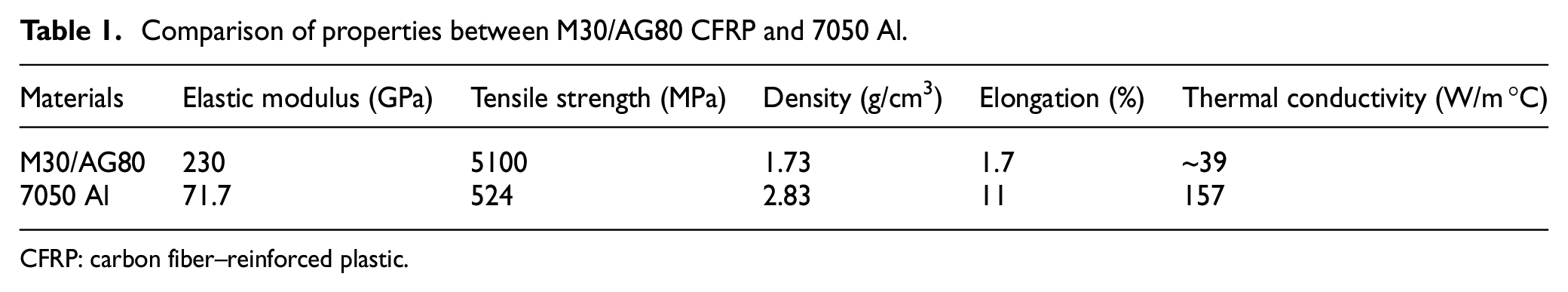
CFRP: carbon fiber–reinforced plastic.
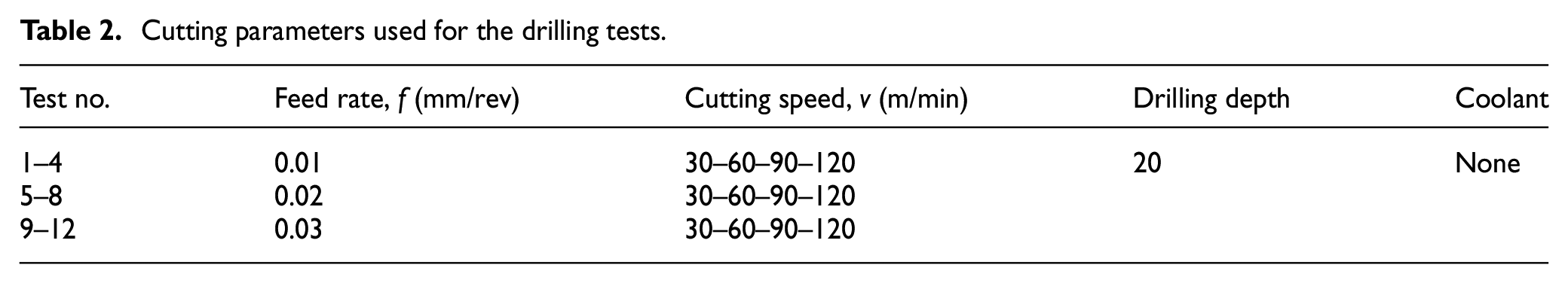
All the dry drilling tests were carried out on a HURCO VMX42 vertical machining center. The force signals were captured by a Kistler 9272 piezoelectric dynamometer connected with a multichannel Kistler 5070A charge amplifier. The drilling temperatures were obtained by a rotational measuring system (RMS) based on the thermocouples embedded in the drill bit. In the RMS, the temperature data for each trail can be stored by a micro acquisition card during the drilling tests and then exported to a PC by USB for data analysis. It should be noted that the force signals and drilling temperatures were obtained at different machining conditions. There was no attempt to analyze the force and temperature signals as this was beyond the scope of the current investigation while they were carefully recorded during the processing. A fresh TiAlN-coated cemented carbide drill bit was used for each of the drilling tests. The specific drill information includes a nominal diameter of 6 mm, a point angle of 140°, a helix angle of 30° and two drill lips. It should be noted that the tool specification was selected according to the designer recommendation and was consistent with that used in practical industrial production. A full factorial experiment was designed and the drilling conditions employed were recommended by the manufacturers of the ACL, as shown in Table 2. The cutting parameters were selected to match the requirements of both the CFRP and Al phases during the processing. All the tests were performed without any coolant similar to the practical industrial production.
Cutting parameters used for the drilling tests.
After all the tests, the typical hole characteristics with respect to the hole diameter, hole cylindricity and roundness were detected by a coordinate measuring machine (CMM). In this article, the hole diameter and hole cylindricity were selected as the main topics for analysis since they directly influence the assembly performance. The drilled hole surfaces under different machining parameters and the tool wear morphology were subsequently observed by an SEM (MIRA3 TESCAN SEM). Furthermore, the hole profiles were also measured by a laser scanning confocal microscope (KEYENCE VK-X200 Series 3D&Profile). The details of workpiece material and experimental procedures are shown in Figure 1.
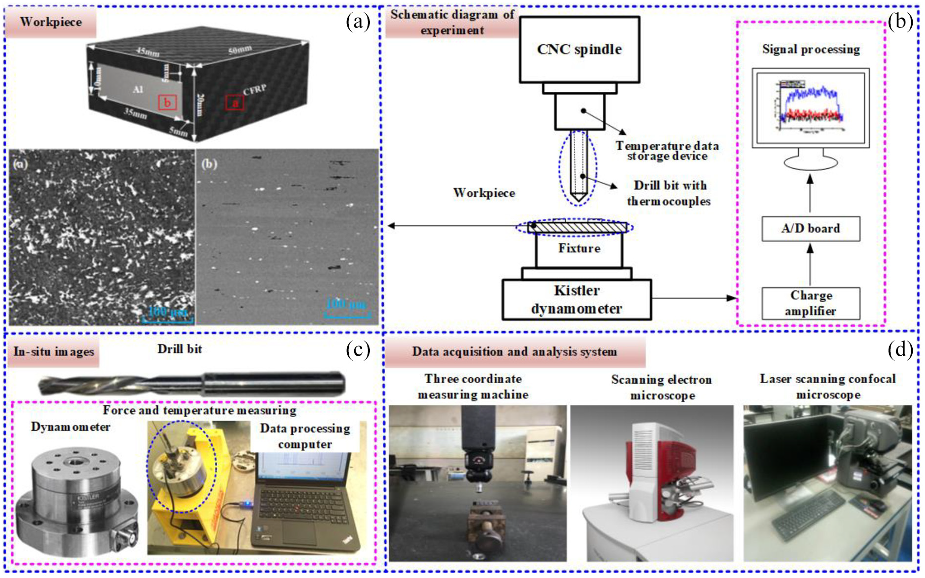
Details of workpiece material and experimental procedures: (a) workpiece material, (b) schematic diagram of experimental setup, (c) drill bit and testing devices, and (d) data acquisition and analysis system.
Results and discussion
Hole diameter
The dimensional tolerance of holes plays an essential role in the assembly and dynamic balance debugging of co-cured material, especially for the military field. However, the different expansion coefficients between the composite layer and metal layer add great difficulty in fabricating consistent holes. The CMM with a ruby ball head of 3 mm was used for measuring and determining the influence of cutting parameters on the hole size distribution. The hole diameters were measured at three positions, which are located at the upper CFRP layer, Al layer and lower CFRP layer, respectively. The measured point in metal layer locates in the middle of Al layer, with details outlined in Figure 2. It should be noted that a fresh tool was used for drilling each hole during the processing to minimize the tool wear effect on the machining results.
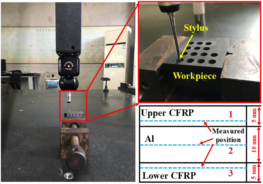
Schematic illustration of the hole diameter measurement.
The evolution of hole diameters for each layer under the employed cutting parameters is plotted in Figure 3. It can be noted that it is obvious the feed rates have a significant influence on the hole diameter of Al layer, especially under a higher cutting speed. However, the hole diameters of both the upper and lower CFRP layers show slight change with the increasing of feed rates, especially under a lower cutting speed. In the lower cutting speeds of 30 m/min and 60 m/min as depicted in Figure 3(a) and (b), the hole diameters of Al layer first increase and then decrease with the elevation of feed rates while the hole diameters in the upper and lower CFRP layers keep basically unchanged. As the cutting speed increases as depicted in Figure 3(c) and (d), the hole diameter of Al layer increases greatly while the hole diameter of lower CFRP decreases. This phenomenon indicates that the cutting speed plays an essential role in determining the hole size during drilling the Al phase since the material deformation was sensitive to the cutting temperatures.
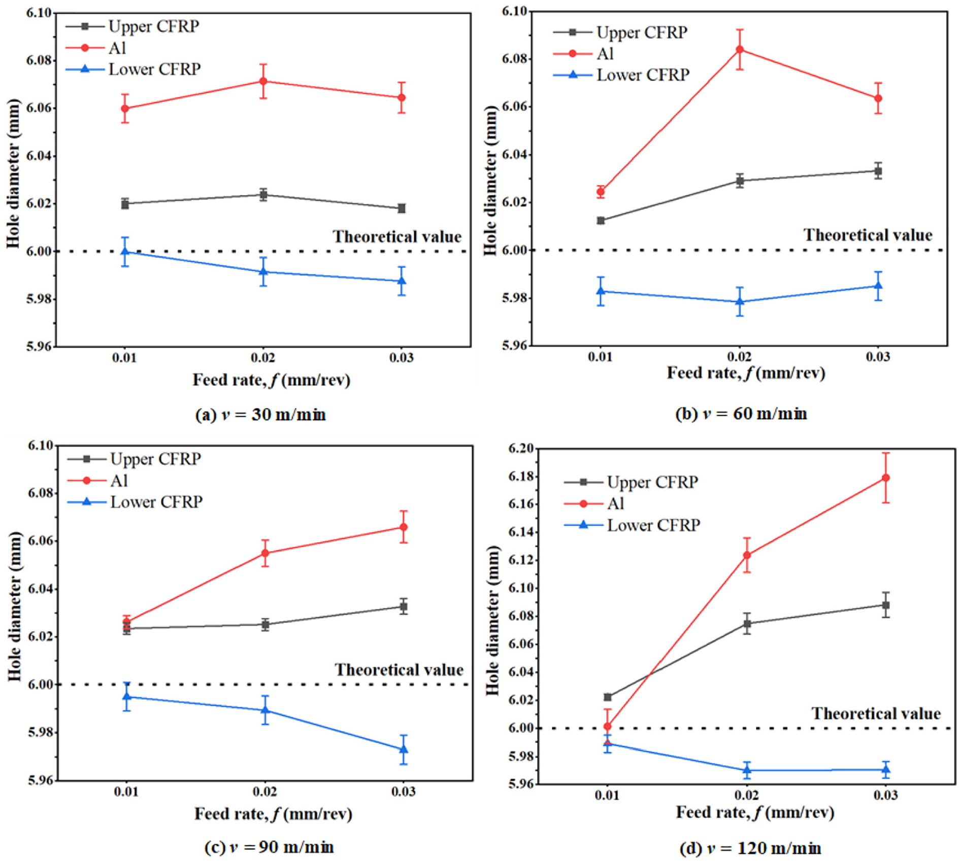
Hole diameter as a function of feed rate in different cutting speeds.
Furthermore, it is clear that the diameter of Al layer is always bigger than both the upper and lower CFRP, indicating strong expansion effect for the utilized Al material during the drilling process. Meanwhile, the produced hole size in either Al phase or upper CFRP phase is totally oversized (the theoretical diameter is 6 mm) regardless of the cutting speeds and feed rates. The predominant factor may be attributed to the influence of chip evacuation on the hole wall circumferences. As the drill bit starts to attack the Al layer, the deformed Al chip shall cause detrimental abrasion on the drilled hole surface of upper CFRP layer. Hence, the original hole size will be enlarged during the chip evacuation process. In contrast, the hole diameter produced in the lower CFRP phase is totally undersized, irrespective of the cutting speeds and feed rates. In this case, the elastic bounce back becomes dominant in shrinking the hole size of lower CFRP layer. As the feed increases, the effect of bounce back becomes gradually obvious.
Hole cylindricity
During the assembly of ACL with other functional components or dynamic balance debugging, the hole cylindricity directly influences the operating performance. In terms of its definition, cylindricity specifies a tolerance zone surrounded by two coaxial cylinders within which the actual surface must lie. The schematic diagram of drilled hole cylindricity is shown in Figure 4(a), and its evolution with the varying cutting speeds at different feed rates is illustrated in Figure 4(b). Note that the cylindricity shows a downtrend as the cutting speed is lower while it gradually increases as the cutting speed becomes higher, especially at increased feed rate. Under the cutting speed of 90 m/min, the cylindricity presents relatively low value irrespective of the feed rate. Meanwhile, the cylindricity shows higher values with the increasing of feed rate, with the minimum values maintained at the lowest feed rate of 0.01 mm/rev at all the used cutting speeds. At lower feed conditions, the material removal rate is relatively small, leading to low friction and heat generation. In this case, the material deformation is reduced while it will become obvious as the feed increases, as shown in Figure 4(b). Meanwhile, the concentricity of the tool was measured at different positions using the dial indicator. The maximum value of the concentricity of the tool is detected as 0.008 mm, which shows the feasibility to obtain the convincing results of hole cylindricity under varying cutting parameters.
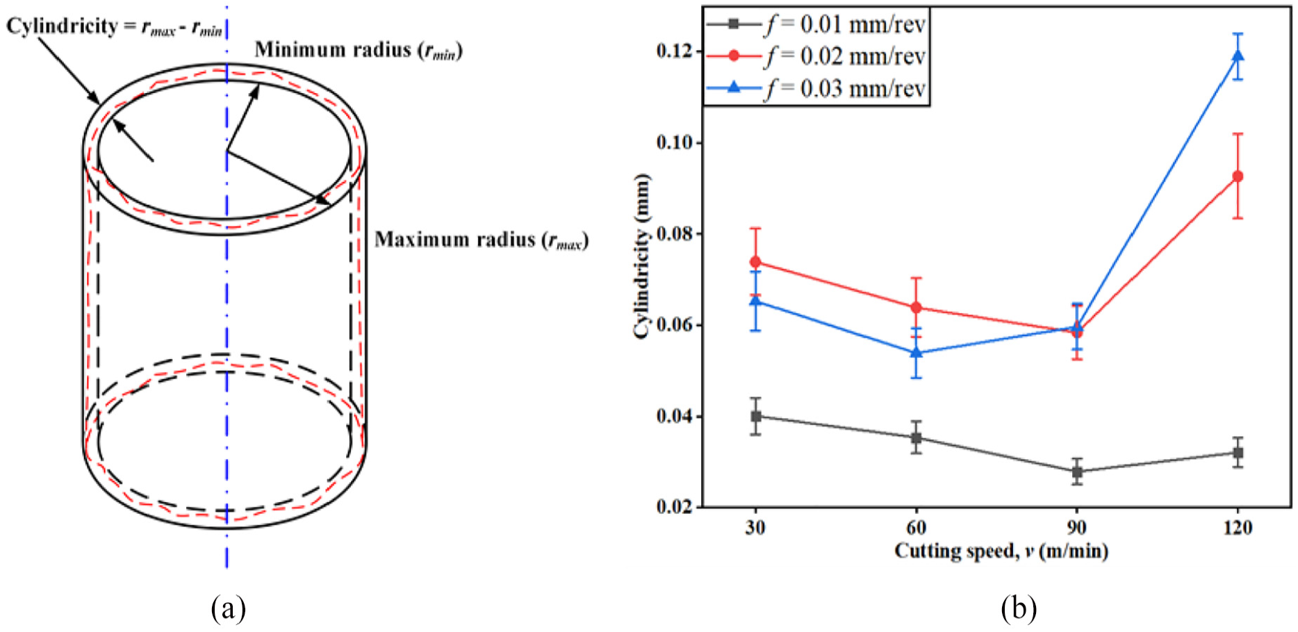
(a) Schematic diagram of hole cylindricity and (b) its evolution as a function of cutting speeds at different feed rates.
Hole surface characteristics
The drilled hole surface quality is another significant aspect influencing the assembly accuracy and product life. During the drilling process of CFRP/Al co-cured materials, three layers are involved in the one-shot cutting process and each phase has its different material removal mechanism. Figure 5 plots the typical mechanisms of material removal process in terms of CFRP and metal cutting. 33 It can be noted that the cutting essence of CFRP is quite different from that of traditional metals when engaged with the rotary tools due to its meso-heterogeneity and macro-anisotropy. In general, fiber crack, resin removal and interface debonding constitute the overall material removal process for CFRP cutting. In this issue, the fiber cutting angle plays an essential role in determining the machined surface quality. As for the metal cutting, the material will undergo the elastic and plastic deformation and then is removed by the cutting tool.
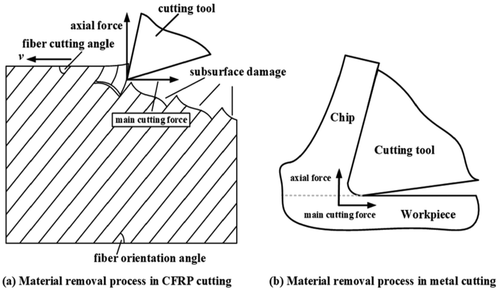
Material removal process in CFRP and metal cutting. 33
The typical three-dimensional (3D) morphologies of hole surfaces in upper and lower CFRP layers and Al layer at different cutting speeds with a constant feed rate of 0.01 mm/rev are shown in Figures 6 and 7, respectively. It is clear that a number of grooves appear on the hole surfaces of CFRP due to the varying fiber cutting angles along the cutting process. Besides, the surface quality in view of the surface roughness presents similar trend with the elevation of cutting speeds. The value of average surface roughness Ra for upper CFRP layer presents lower magnitudes compared to that in lower layer regardless of the cutting parameters. This phenomenon can be attributed to the higher thrust forces and higher drilling temperatures produced in the lower CFRP layer since matrix degradation and thermal alteration are easily to occur under high cutting temperatures. As for the hole wall of Al layer, fiber debris and a great amount of chip stick to the surface after the drilling. This can be explained by the fact that the temperature is much higher during drilling the lower CFRP and hot CFRP powders as well as the Al chip will be generated and easily adhered to the hole wall of Al during the evacuation process. During the drilling of CFRP/Al co-cured materials, the chips are produced in the form of powders for CFRP and continuous strips for Al. Due to the semi-closed feature of drilling operation in addition to the special structure of the utilized workpiece, it is difficult to produce an excellent surface finish on both the CFRP and Al layers. In order to better identify the drilled hole surface morphology, gold powders were sprayed on the samples and then observed by SEM.
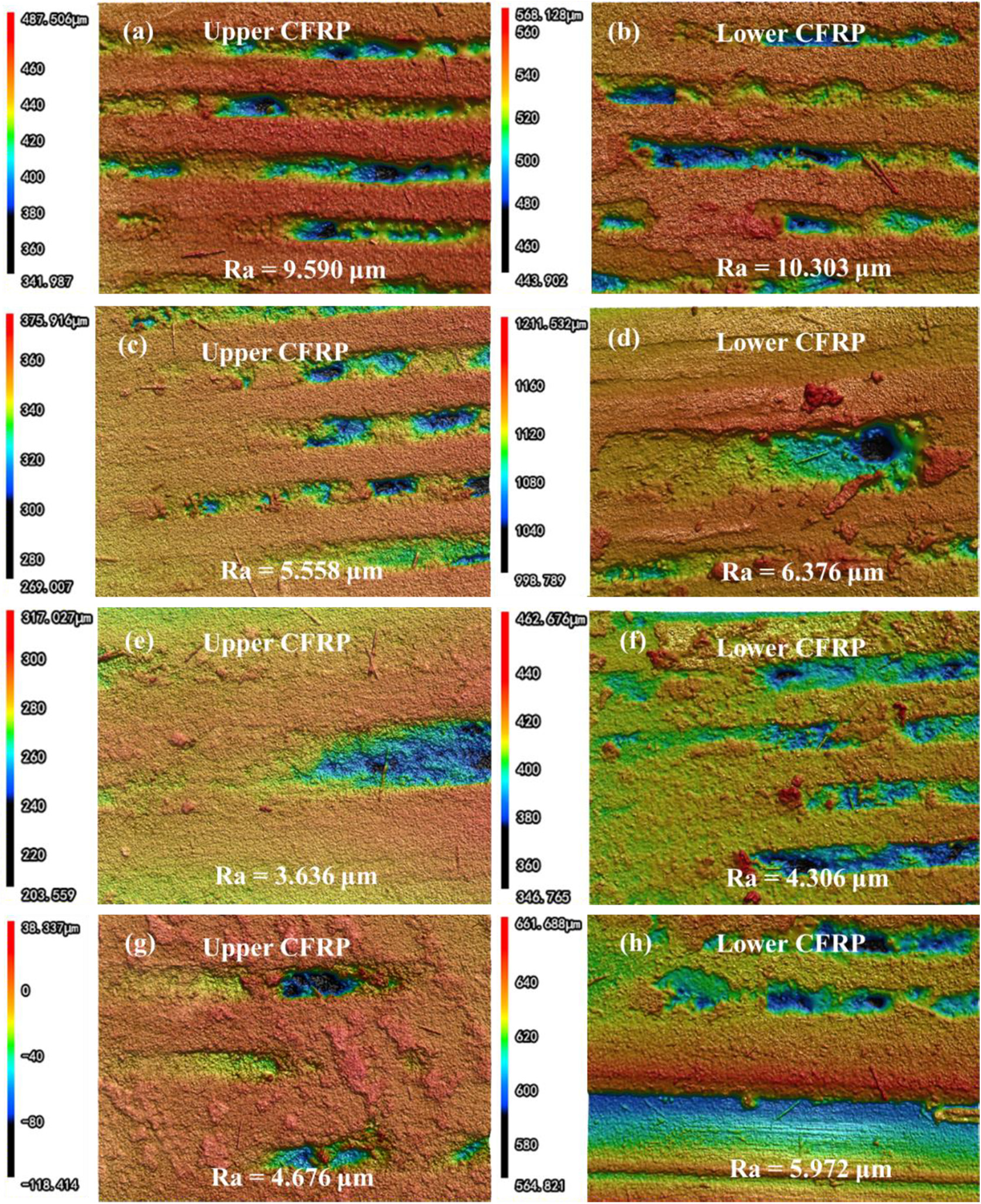
Hole surface morphologies of the upper and lower CFRP phases with a constant feed of 0.01 mm/rev and cutting speeds: (a, b) 30, (c, d) 60, (e, f) 90, (g, h) 120 m/min.
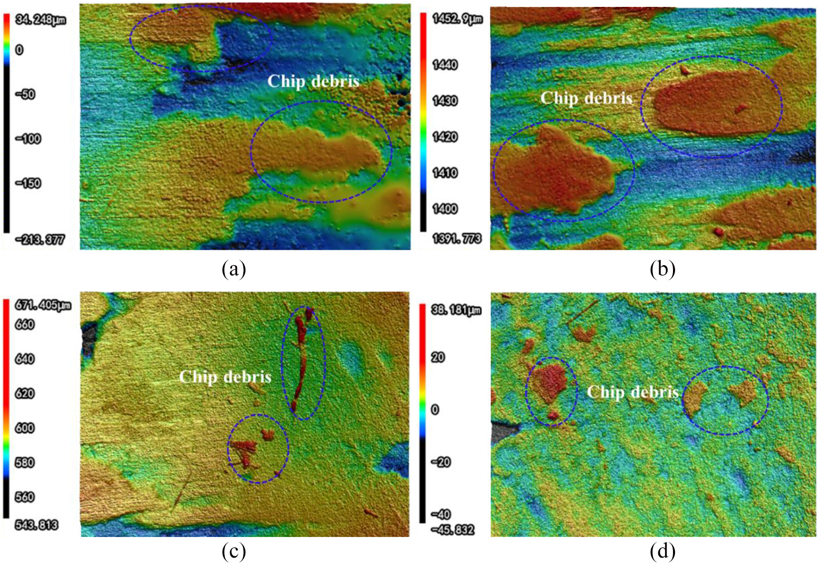
Hole surface morphologies of the Al phase at different machining conditions: (a) v = 30 m/min, f = 0.01 mm/rev; (b) v = 60 m/min, f = 0.01 mm/rev; (c) v = 90 m/min, f = 0.01 mm/rev; and (d) v = 120 m/min, f = 0.01 mm/rev.
Figures 8 and 9 show the typical machining defects by SEM in the CFRP and Al layers, respectively. It can be noted that several types of machining defects for CFRP drilling appeared, which can be categorized as the cavity area and smooth area. The defects produced on the cavity area can be attributed on the one hand that the fiber/matrix debonding, fiber bending cracks and shearing cracks, and on the other hand the Al chip evacuation rubbing against the hole surface. Rough surfaces induced by the fiber debris and chip residue also appeared on the hole surface of Al layer, which is different from the results obtained by Wang et al. 27 During drilling the lower CFRP layer, hot CFRP powder chips induced by the high drilling temperatures expel from the upper surface of the workpiece, which go through the entire hole wall of Al phase. Therefore, much fiber debris and Al chip would stick to the hole wall, causing rough hole wall surfaces for the Al layer.
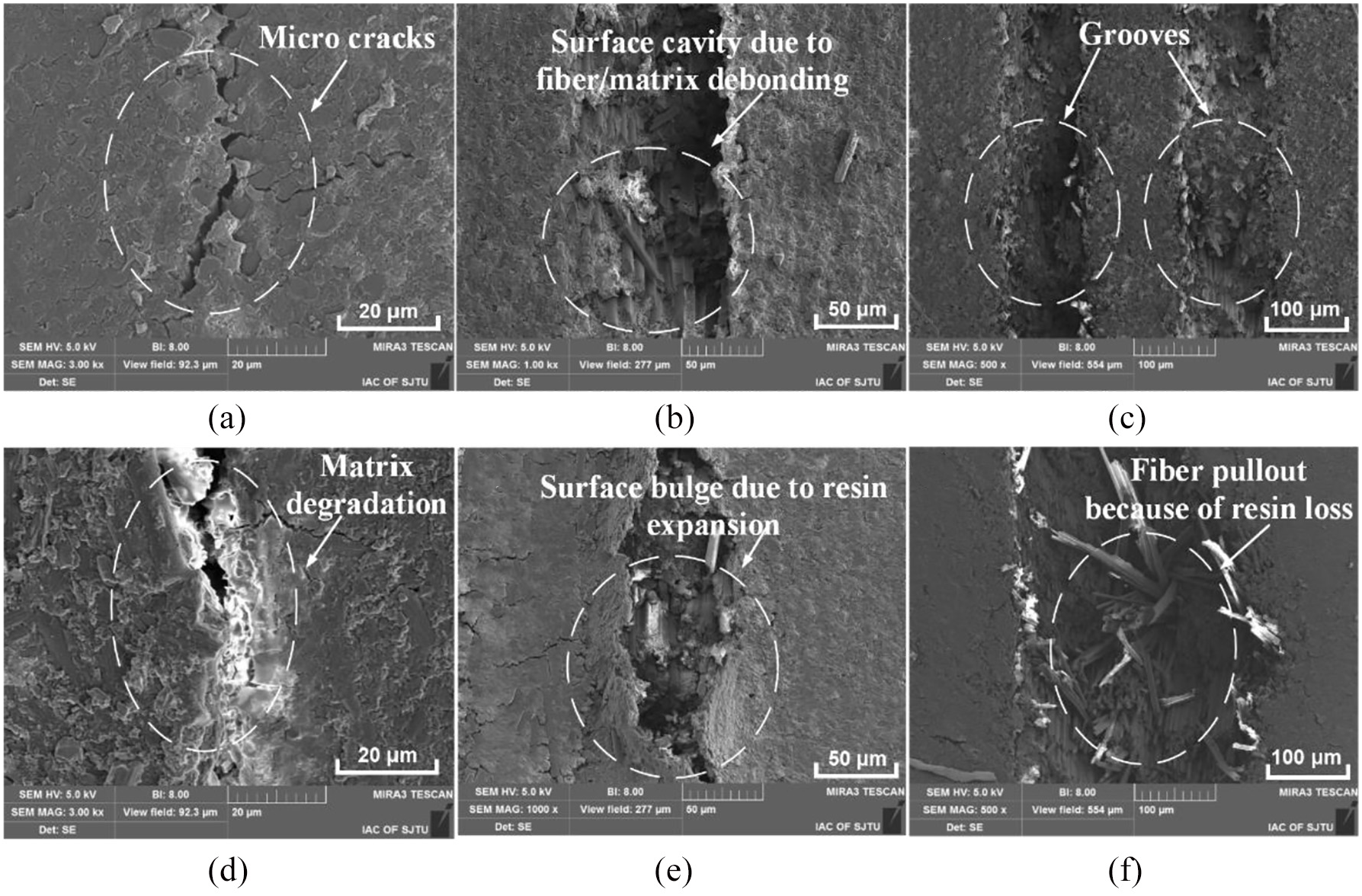
Typical machining defects in the drilled hole surfaces of CFRP layers: (a) micro cracks, (b) surface cavity, (c) grooves, (d) matrix degradation, (e) surface bulge, and (f) fiber pullout.
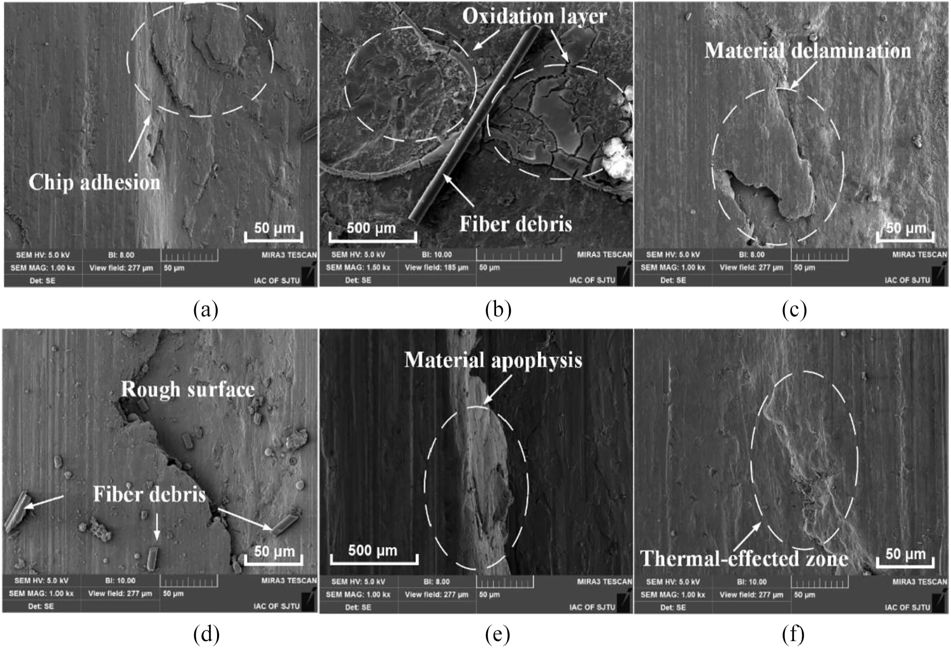
Typical machining defects in the drilled hole surfaces of Al layer: (a) chip adhesion, (b) oxidation layer, (c) material delamination, (d) fiber debris, (e) material apophysis, and (f) thermal-effected zone.
Tool wear characterization
In the drilling operations of CFRP/Al co-cured material, the contact condition between the drill bit and machined workpiece physically changed as the drill cuts from one layer to another layer. The wear modes of the active zones in drill bit will thereafter be affected by the tool-work contact conditions. As a matter of fact, tool wear is known as one of the most essential criteria in evaluating the machinability of the workpiece. In other words, tool wear modes directly influence the tool life, machined quality and production cost. In this work, the morphologies of all the tested worn tools after the drilling tests were measured by SEM in order to figure out the dominant wear mechanisms during drilling CFRP/Al co-cured material. The SEM micrographs were focused on the zones of chisel edge, main and minor cutting edges and drill edge corner since the extent of flank wear affects the hole quality while the extent of chisel edge wear determines the magnitudes of thrust forces, while both of them are key factors in evaluating the tool life.
Figure 10 shows the typical drill morphology after conducting the drilling test under the cutting parameter of the feed rate of 0.03 mm/rev and cutting speed of 120 m/min. The SEM results reveal that the mechanical abrasion operates as the dominant wear mode for cutting edges in view of their wear signatures. When machining CFRP layers, the reinforcing carbon fibers act as strong abrasives, resulting in the edge blunting (cutting edge rounding). A uniform wear trace formed on the drill flank face and no adhesion was found near the cutting edge due to the strong mechanical abrasion, followed by the carbide substrate exposure. Besides, some micro cavities due to adhesive Co loss were observed in the close-up view of point A on the wear region (see Figure 10).
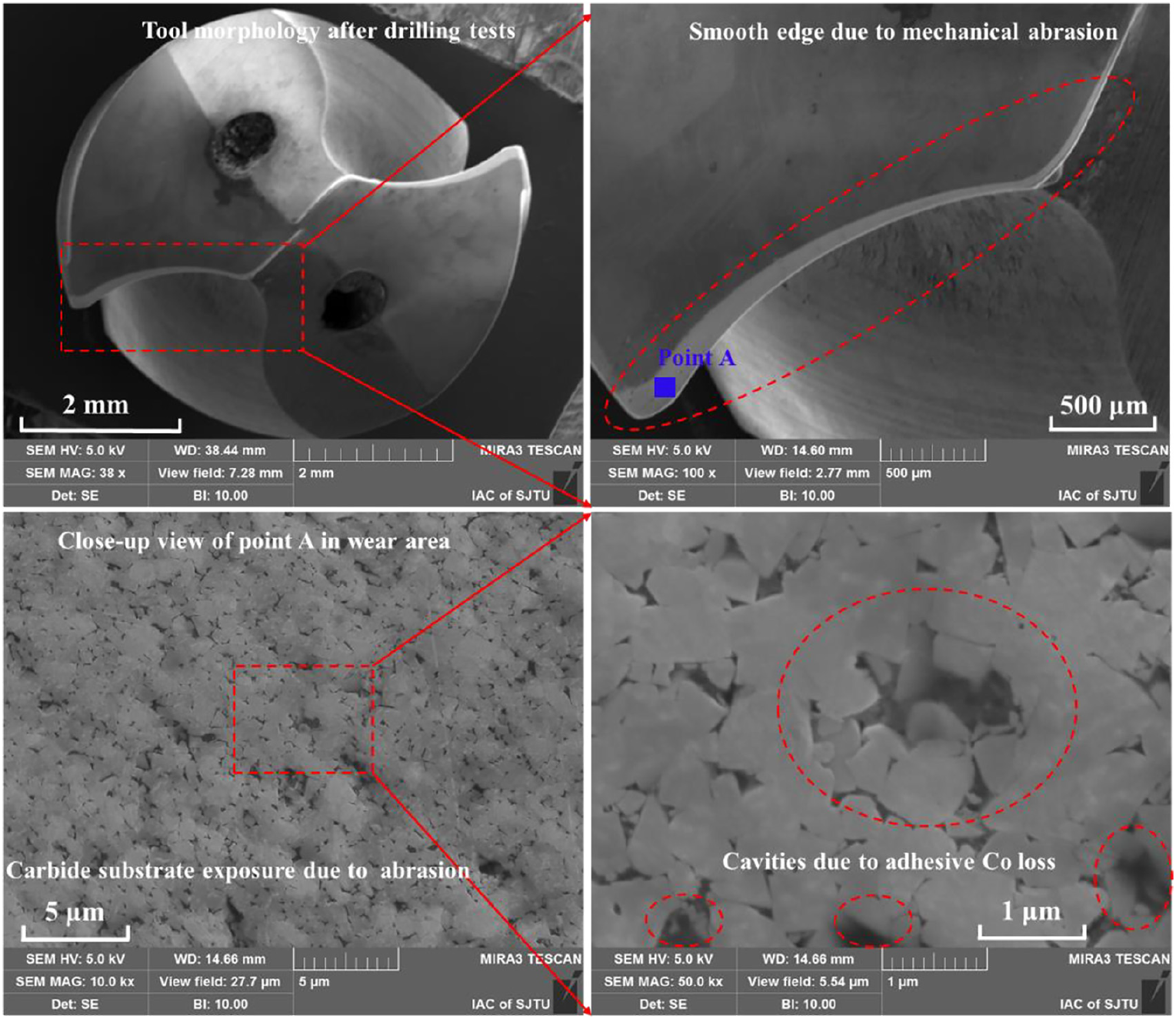
Signs of strong mechanical abrasion during the drilling process.
Figure 11 depicts the typical close-up views of chisel edge, major cutting edge, minor cutting edge and drill edge corner of the drill bit in Figure 10 in order to comprehensively understand the dominant wear mechanisms when machining the assigned co-cured material. It can be noted that the formation of composite debris adhesion and Al chip adhesion within the chisel edge zone concerns with the high temperatures and pressures due to the strong extrusion action between the drill and workpiece instead of shearing. It is obvious that abrasive marks formed in the vicinity of both major cutting edge and minor edge, with average flank wear (VB) maintained at 130 μm. Besides, the tool coating on the drill edge corner was also peeled off with the action of mechanical abrasion, which will eventually accelerate the tool wear and induce catastrophic failures like plastic deformation or edge fracture. However, there is no evidence of Al chip adhesion and chipping within the edge regions due to the brushing effect of carbon fibers when the CFRP layers are machined. The adhesion of Al chips near the tool cutting edges will be smoothed away when the drill finalized the lower CFRP layer cutting since the carbon fibers are characterized as high hardness and high abrasives, and edge chipping based on adhesion is thereafter restrained.
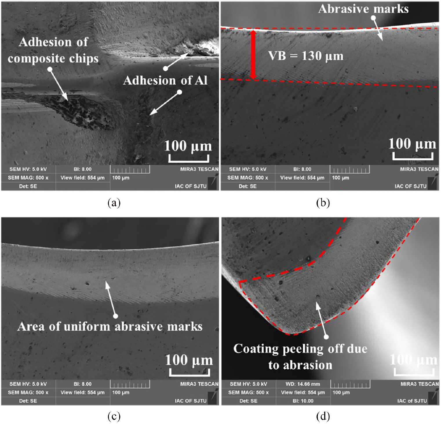
Morphologies of (a) chisel edge, (b) major cutting edge, (c) minor cutting edge and (d) edge corner after drilling tests.
Figure 12 shows the examined zones of wear regions and detected points as well as their element distribution using energy dispersive spectrometer (EDS) technology. Point A was inspected on the adhered material on the tool rake face and point B was inspected on the tool coating layer, both of which are located near the tool chisel edge. Furthermore, another two points C and D are inspected on the worn region near the minor cutting edge. The element distribution of points A and B reveals the presence of Al chips welding onto the drill chisel edge zone. However, extents of Al chips show a sharp downtrend near the drill main edges due to the brushing effect of carbon fibers when the CFRP layer is drilled. Meanwhile, the abrasive wear becomes apparent and the radius of the cutting edge is enlarged under the mechanical abrasion.
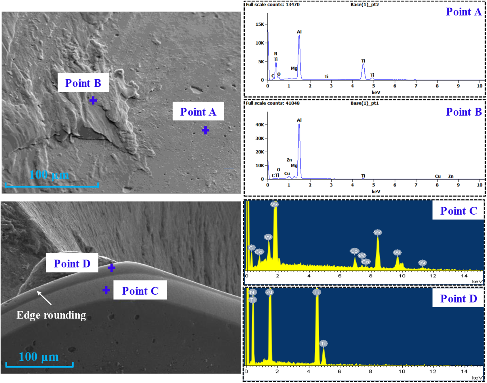
EDS results of the wear area after drilling tests.
Table 3 quantitatively illustrates the element contents of point A, B (near chisel edge), C and D (near minor cutting edge) in Figure 12 in order to identify the element distribution of tool wear region. The element distribution of point A represents the constitution of tool coating material while elements Al, Zn, Mg, Cu in point B show the original material components of workpiece Al layer that to be drilled. The recorded elements in point C are the typical ingredients of tungsten carbide drill bit employed while elements in point D indicate the characteristics of unworn area near the cutting edge.
The EDS analysis of point A, B, C and D in Figure 12.
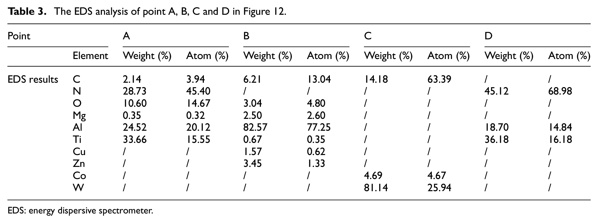
EDS: energy dispersive spectrometer.
Conclusion
The main objective of this article was to figure out the associated hole characteristics and tool wear modes during dry drilling of a new developed CFRP/Al co-cured material. For this purpose, drilling studies were carried out with the manufacturer-suggested cutting parameters being cutting speed and feed rate varied.
The hole quality was investigated with a particular focus on the hole diameter, hole cylindricity and hole surface characteristics. It was noted that the hole diameter at different layers shows disparate values but similar size regularity being the Al layer the largest one followed by the upper CFRP and lower CFRP layer, respectively. The hole diameters of both Al layer and upper CFRP layer were totally oversized while it became downsized for the lower CFRP due to the dominant bouncing back effect. Higher cutting speed and feed rate promote an increased level of hole diameter for Al and upper layers, enlarging the hole cylindricity as a consequence of cutting heat accumulation. Furthermore, it was found that the cutting speed of 90 m/min and feed rate of 0.1 mm/rev are more productive parameters in view of the desired hole quality. Grooves and matrix degradation are the main machining defects for CFRP layers while chip adhesion is the case for Al layer under the mechanical and thermal action.
The tool wear modes observed in the assigned cutting conditions were mainly abrasive wear being maintained at the vicinity of major/minor cutting edges and drill edge corner, followed by chip adhesion on the chisel edge region. Regarding the morphologies of tool edges, it was observed as the formation of cutting edge rounding and more smooth abrasive wear due to the brushing effect of carbon.
The results gathered to fulfill a twofold aim: understanding the characteristics of drilled holes and tool wear mechanisms under the assigned cutting conditions and increasing the hole quality using more productive cutting variables. By this means, it would be possible to give explicit guidance and thereby improve drilling performance during the assembly of co-cured material and dynamic balance debugging, enhancing the competitiveness of the process.
Footnotes
Declaration of conflicting interests
The author(s) declared no potential conflicts of interest with respect to the research, authorship, and/or publication of this article.
Funding
The author(s) disclosed receipt of the following financial support for the research, authorship, and/or publication of this article: Financial support for the research is acknowledged. This work was supported by the National Natural Science Foundation of China (no.: 51605281, 51875355) and SAST-SJTU Joint Research Center for Aerospace Advanced Technology (USCAST2016-14).