
Abstract
Both electrical discharge machining and electro-arc machining are non-contact machining processes, which use high temperatures produced by discharges to erode material. The gap between the tool and the workpiece is usually filled with liquid dielectric medium. Moreover, liquid flushing is commonly used in the machining processes of electrical discharge machining and electro-arc machining. Much research has been conducted to study the effects of flushing on these processes. However, there has been little study on the mechanism of the flushing procedure for these machining processes. In this article, electrical discharge machining and electro-arc machining experiments adopting different polarities and flow rates were designed and implemented. The plasma tunnel and crater morphology were studied. It was found that the plasma tunnel was lengthened, compressed and broken by flushing in the electro-arc machining experiment; however, the electrical discharge machining experiment did not produce this result. Similarly, tailing discharge craters and polarity effects caused by flushing were observed in the electro-arc machining experiment, while no such performances caused by flushing were found in the electrical discharge machining experiment. The flushing in electro-arc machining was able to reduce the material removal rate, tool wear rate and surface roughness simultaneously, while the effects of flushing in electrical discharge machining were inconspicuous. Moreover, the characteristics of the plasma tunnels of the electro-arc machining experiment were similar to those of arcs, which were different from those of the electrical discharge machining experiment. These results help to verify that the electro-arc machining process adopts arcs, while the electrical discharge machining process adopts sparks, during their respective material removal processes.
Keywords
Introduction
Electrical discharge machining (EDM) is widely used for the machining of difficult-to-cut materials using the thermal energy of pulsed electric sparks generated between the tool and the workpiece. 1 The discharge gap between the tool and the workpiece is filled with a dielectric medium, usually liquid. 2 Debris and bubbles generated by the sparks are expelled in the dielectric medium. 3 Since this aggregated debris and bubbles may cause abnormal discharges, arcs and short circuits, two methods are commonly adopted to improve the EDM process, namely, the mechanical motion arc breaking method and the flushing arc breaking method. 4 The mechanical motion arc breaking method adopts the relative movement of the tool and the workpiece, including any jumping, shaking, vibrating or rotating of the tool or the workpiece. The flushing arc breaking method adopts dielectric flushing, including central ejecting or imbibing through holes of the tool or the workpiece, as well as side flushing which ejects dielectrics through nozzles near the discharge gap.
The machining speed of EDM is low; therefore, the electro-arc machining (EAM) technique has been proposed and researched recently. In contrast with EDM, which uses sparks with a duration within 1000 µs, 5 EAM adopts arcs with a duration, that is, usually longer than 100 µs to erode materials. 6 Essentially, to distinguish between EDM and EAM, the discharge current should also be considered. The boundary between EDM and EAM is fuzzy. 7 For sure, both sparks and arcs are plasma tunnels. The arcs are more stable and higher in energy density than the sparks; this stability and density promotes the machining speed of EAM.4,5 The commonly used EAM processes, including arc dimensional machining (ADM), electro-melting-explosion (EME), short electrical arc machining (SEAM), blasting erosion arc machining (BEAM) and ultra-high-speed combined machining of EDM and arc machining, are similar to EDM in that they all adopt flushing to overcome discharge concentrations and to break arcs. The commonly used EDM and EAM processes and their flushing methods are listed in Table 1.
EDM and EAM processes and their flushing methods.
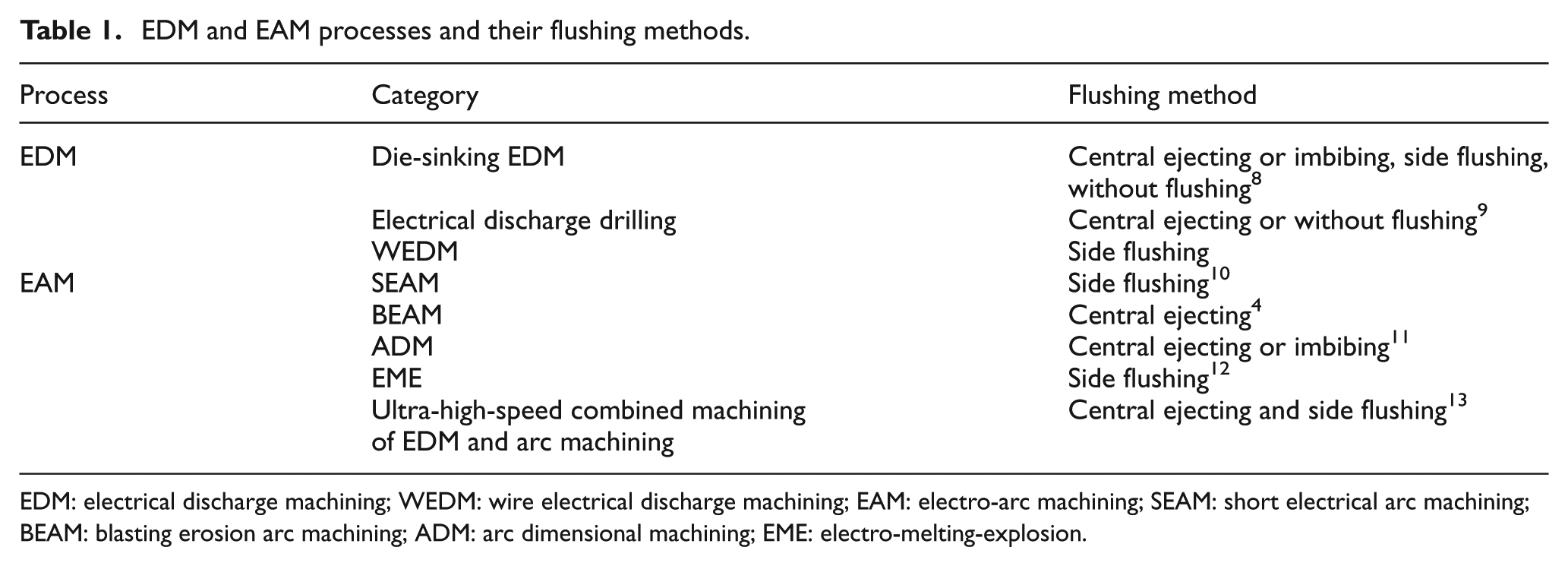
EDM: electrical discharge machining; WEDM: wire electrical discharge machining; EAM: electro-arc machining; SEAM: short electrical arc machining; BEAM: blasting erosion arc machining; ADM: arc dimensional machining; EME: electro-melting-explosion.
As shown in Table 1, EDM and EAM processes adopt similar flushing methods. More interestingly, tailing discharge craters caused by flushing have been found in both EDM and EAM processes,4,14–16 which are similar in geometry but different in size. The tailing discharge crater is an important implication of flushing.
Much research about the effects of flushing on the material removal rate (MRR), tool wear rate (TWR) and surface roughness (Ra) using the Taguchi method and multi-objective optimization has been carried out.17–19 However, little research has been done on the mechanism of flushing. The effects of flushing on EDM and EAM are still ambiguous. In practical machining, the flow rate of flushing is selected by experience merely, which is unfounded and unscientific. Therefore, this research was performed to study the mechanism of flushing in EDM and EAM. Single-pulse experiments covering EDM and EAM with different polarities and flow rates were designed and carried out. The results including the plasma tunnel, crater geometry and element distribution were adopted to reveal the mechanisms of flushing in EDM and EAM.
Experimental setup and procedure
The experimental setup and procedure are shown in Figure 1. The experiments were conducted on a computer numerical control (CNC) machine tool developed by our research group. The single-pulse power source was self-made with an open-circuit voltage of 260 V and a real-time measuring and controlling system. The system started a timer when the discharge current was measured and shut the discharge off when the discharge duration (timed by the timer) was reached, thus equal energy of each discharge can be realized. The discharge duration could be adjusted from 60 to 65,535 µs. The current-limiting resistance was 2.5 Ω. The discharge voltage and current were recorded by an oscilloscope with a current probe. The polarity of the workpiece was switched by a reverse switch. The tools were brass needles with a cone angle of 37°. The workpieces were made of tool steel W18Cr4V. Pure water was selected as the dielectric medium and pumped to the discharge gap through a nozzle. The flow rate was adjusted by a regulator and monitored by a flowmeter. The diameter of the flushing hole in the nozzle was 3 mm. The angle between the axis of the nozzle and the workpiece surface was 20°. The distance between the lowest point of the nozzle and the discharge point was 4 mm, as shown in Figure 1(a). Since the nozzle was fixed on the tool fixture, the flushing direction and position remained constant during each trial.
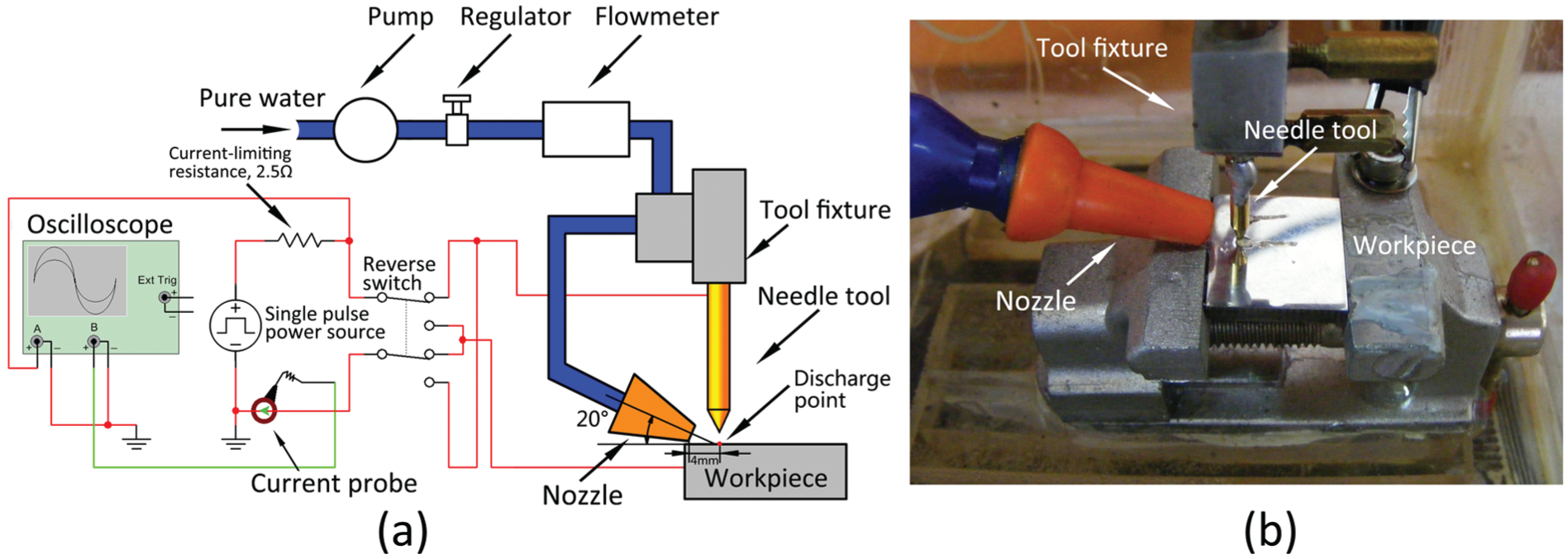
(a) Experimental setup illustration and (b) photograph of the experimental procedure.
The discharge gap was 20 µm, adjusted before every trial. The peak current was 80 A. The typical discharge durations, including 60 and 20,000 µs, were selected. Thus, two experiments covering EDM and EAM were constituted, namely, the EDM experiment and the EAM experiment. The workpiece polarity (the polarity discussed in this article) has two levels, and the flow rate has four levels. The arrangements of the two experiments are given in Table 2.
Arrangements of the two experiments.
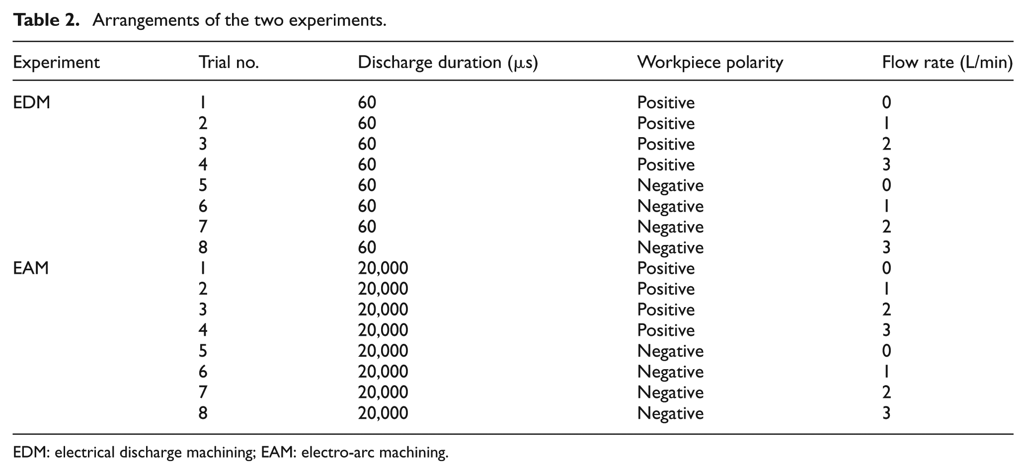
EDM: electrical discharge machining; EAM: electro-arc machining.
Results and discussions
The two experiments were carried out one by one, and each trial was repeated four times. All craters in the EDM experiment are shown in Figure 2. The crater geometries of the different trials were uniform, although different machining parameters were adopted. The difference among these craters is that the craters of positive polarity, shown in Figure 2(a), have less Cu than those of negative polarity, shown in Figure 2(b), which will be discussed further below.
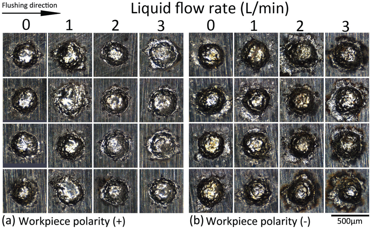
Craters of (a) positive and (b) negative polarities with different flow rates produced by the EDM experiment.
The craters of the EAM experiment were significantly affected by the polarity and flow rate, as shown in Figure 3. The craters became smaller and tails were formed when the flushing was adopted. The polarity also affected the distribution of Cu.
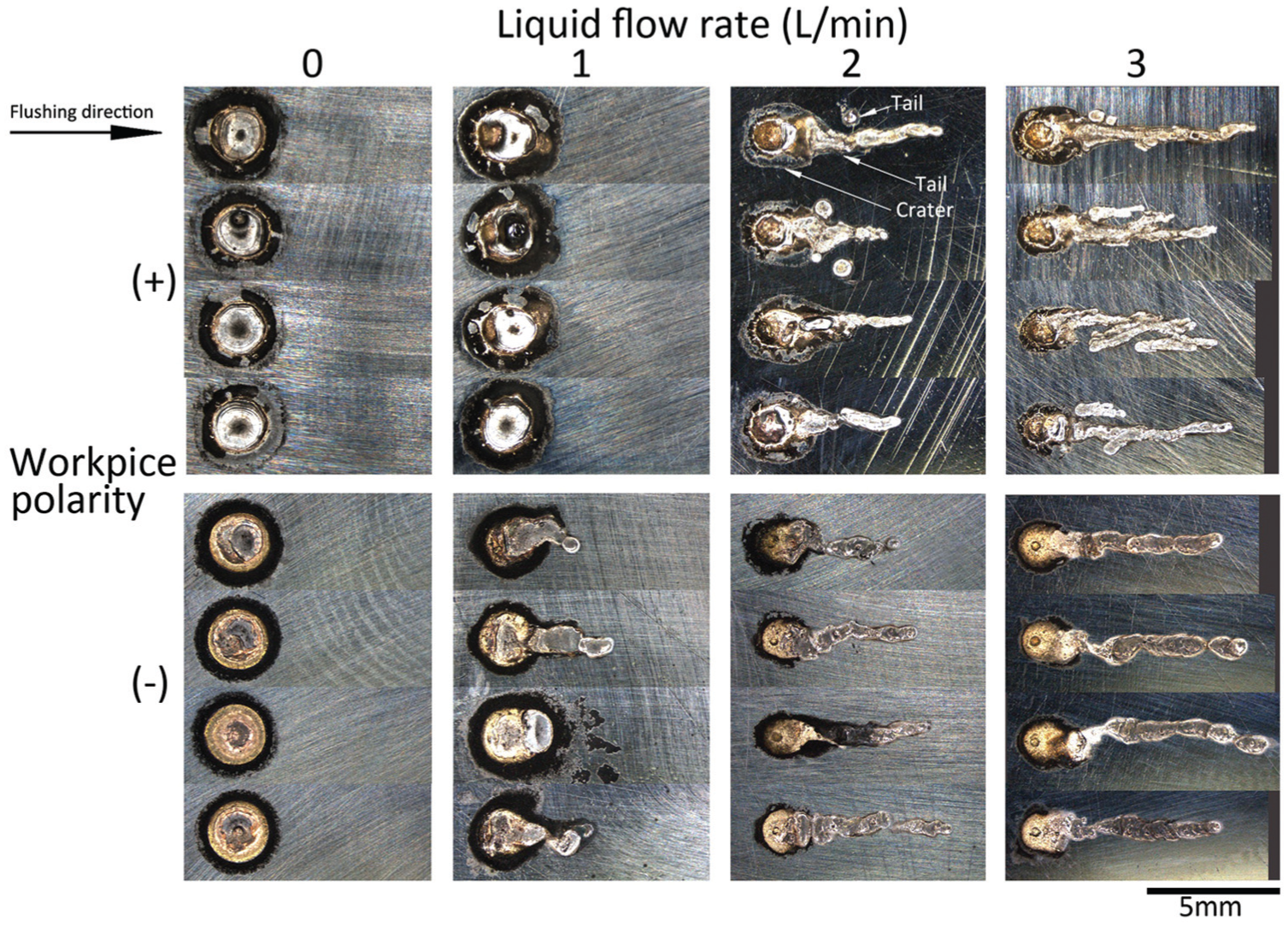
Craters of (a) positive and (b) negative polarities with different flow rates produced by the EAM experiment.
The flushing created tailing discharge craters in the EAM experiment. In contrast, no tailing discharge crater was found in the EDM experiment. It was gas or frog flushing adopted by the literatures14–16 about tailing discharge craters of EDM. However, there is no research about tailing discharge craters of EDM generated by liquid flushing. Only one study 20 achieved tailing discharge craters using the relative movement of the tool and the workpiece in a liquid medium. However, to generate the tailing discharge crater in EDM, the relative speed of the tool and the workpiece should be faster than 30 µm/µs, 20 while the flushing speed cannot be reached easily. This could explain why a tailing discharge crater cannot be produced using liquid flushing in EDM.
Discussions on details about the plasma tunnel, crater, breaking of arcs and polarity effects of the two experiments are shown as follows.
Plasma tunnel and crater diameter
The plasma tunnel diameter is little larger than the crater diameter. 21 However, the plasma tunnel is non-uniform, and it is difficult to observe and measure the plasma tunnels. The assumption that the plasma tunnel diameter equals the crater diameter is employed in this article. The schematics of flushing in the experiments are shown in Figure 4. The plasma tunnels of the EDM experiment and the trial 1 of the EAM experiment were formed after the breakdown, as shown in Figure 4(a). When the discharge duration was long enough and the flushing was adopted, as in the trials 2–4 of the EAM experiment, the plasma tunnels were lengthened and compressed, as shown in Figure 4(b). A right triangle was formed by the gap width, tailing length and maximum plasma tunnel length. Since the gap width (20 µs) was much less than the tailing length (more than 1 mm), as shown in Figure 4(b), it was recognized that the maximum plasma tunnel length equaled the tailing length. The changes in crater diameter (Dc) with the flow rate of the two experiments are shown in Figure 4(c) and (d). The maximum plasma tunnel length (i.e. the tailing length) was measured and shown in Figure 4(e). It can be seen in Figure 4 that the crater diameters of the EDM experiment were similar, even though different flow rates were chosen. However, the crater diameters of the EAM experiment decreased as the flow rate increased. Moreover, the length of the tailing discharge crater and the maximum plasma tunnel length grew as the flow rate increased.
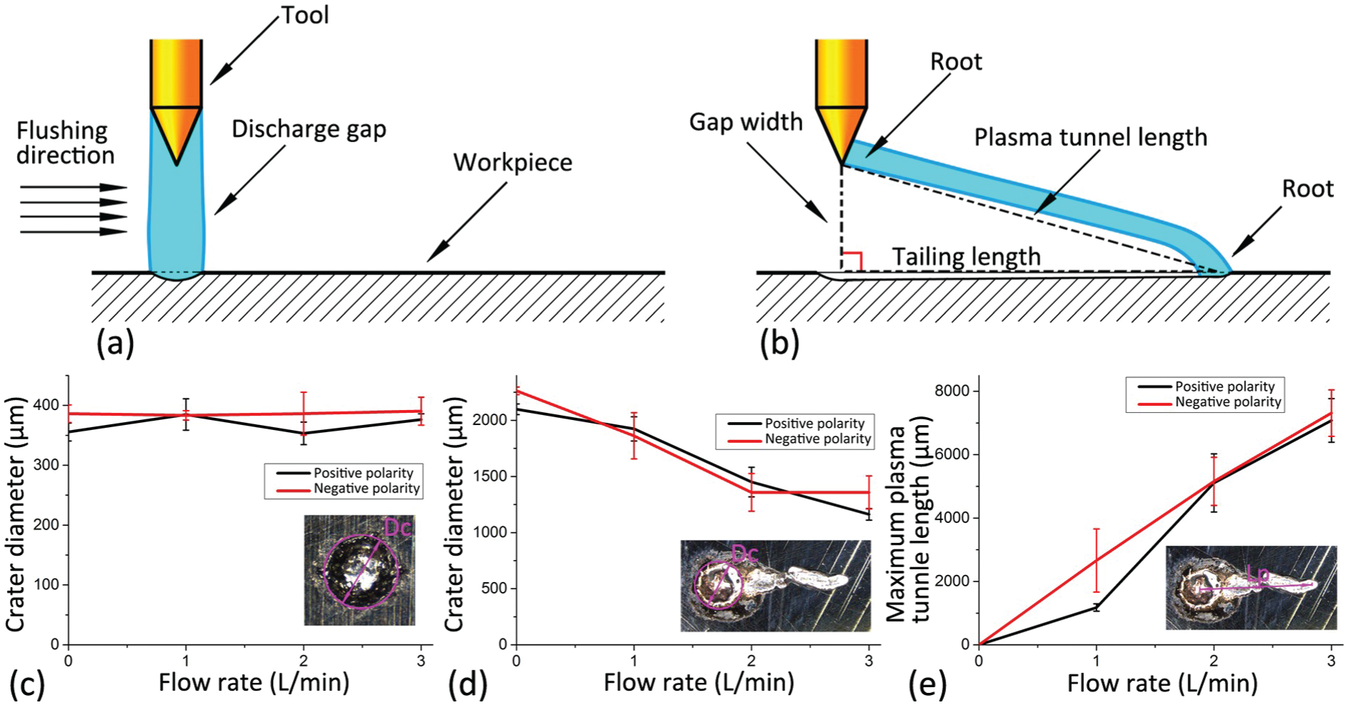
Illustrations of (a) unaffected and (b) affected plasma tunnels by flushing, effects of the flow rate on the crater diameter of (c) the EDM and (d) EAM experiments, and (e) the maximum plasma tunnel length of the EAM experiment.
The plasma tunnel diameter decreased and the maximum plasma tunnel length lengthened as the flow rate grew, which revealed the effects of flushing on the plasma tunnel. It is concluded that the flushing can lengthen and compress the plasma tunnel at the same time. The compression can be explained by the minimum voltage principle. As the plasma tunnel is force-cooled by the flushing medium, the plasma tunnel diameter contracts to decrease heat dissipation. 22 Moreover, the flushing cools down the tool and the workpiece, which indirectly cools the plasma tunnel, especially the roots (the ends of the plasma tunnel), and ultimately decreases the plasma tunnel and crater diameter. In addition, flushing can compress the plasma tunnels as well. An experimental equation has been put forward to describe the compression of plasma tunnels in air by air flushing as 23
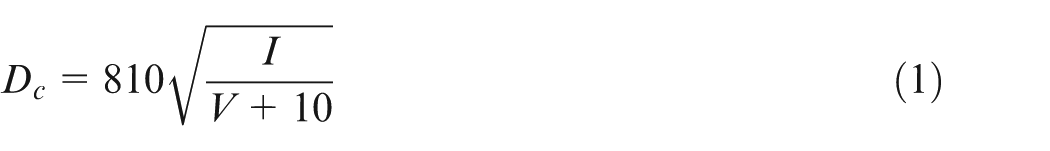
where Dc is the plasma tunnel diameter (µm), I is the discharge current (A), and V is the flushing speed (µm/µs). The flow rate was 0–3 L/min in the experiments, so the flushing speed was approximately 0–7.14 µm/µs considering the nozzle diameter of 3 mm. The actual plasma tunnel diameter in the experiments was smaller than the corresponding calculated value in equation (1). The explanation for this is that the liquid dielectric medium can compress the plasma tunnel more strongly and absorb more heat than air. However, the plasma tunnel diameter is inversely related to the flushing speed, which is coincident with the results in equation (1). On the whole, the cooling and lengthening caused by flushing can compress the plasma tunnel simultaneously.
Breaking of plasma tunnels
Both the spark of EDM and the arc of EAM are plasma tunnels. The understanding of the spark is not enough because of its tiny size, rapid changes and short lifetime. The arc, on the other hand, has been well researched and its related features have been introduced by plasma physics. The discharge durations of the two experiments were 60 and 20,000 µs, respectively. The lifetime of the plasma tunnel (the plasma tunnel in this article refers to a spark or an arc) should be equal to the corresponding discharge duration if no breaking of plasma tunnels occurs. The lifetime of the plasma tunnel was determined by the actual discharge duration measured by the discharge waveforms. The discharge waveforms of the EDM experiment of different flow rates were uniform. The lifetime of every plasma tunnel in the EDM experiment was 60 µs, and no breaking of plasma tunnels was found.
The results of the EAM experiment were different from those of the EDM experiment, and breaking of plasma tunnels did occur. The discharge waveforms of the flow rates of 0 and 3 L/min are shown in Figure 5(a) and (b). The discharge voltage and current without flushing changed slightly after breakdown while those with flushing changed dramatically. Meanwhile, the discharge voltage changed in the opposite direction of the current, which reveals the disturbance of the flushing on the plasma tunnel. The lifetime of the plasma tunnel in Figure 5(a) was 20,000 µs and equaled the discharge duration, which indicates that there was no breaking of plasma tunnels when the flow rate was 0 L/min. The lifetime of the plasma tunnel in Figure 5(b) was shorter than 20,000 µs. The discharge ended early; when the discharge voltage was restored, the discharge current dropped to 0 A at the same time, which indicated that the plasma tunnel was broken by flushing. The lifetime of the plasma tunnel of positive and negative polarities is shown in Figure 5(c), which indicates that the high flow rate can break the plasma tunnels. An empirical formula 23 was put forward to describe the maximum length of the plasma tunnel free burning in air as
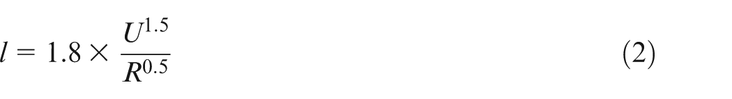
where l is the maximum length of the plasma tunnel (µm). U is the voltage of the power source (equal to the open circuit voltage) (V). R is the current-limiting resistance of the discharge circuit (Ω). The calculated maximum length of the plasma tunnel was shorter than the corresponding experimental result when the maximum flow rate was chosen. The reasons are as follows: the compression of the plasma tunnel caused by the liquid dielectric medium reduced the plasma tunnel diameter. The energy density of the plasma tunnel was simultaneously increased, which made the breaking of the plasma tunnel more difficult.
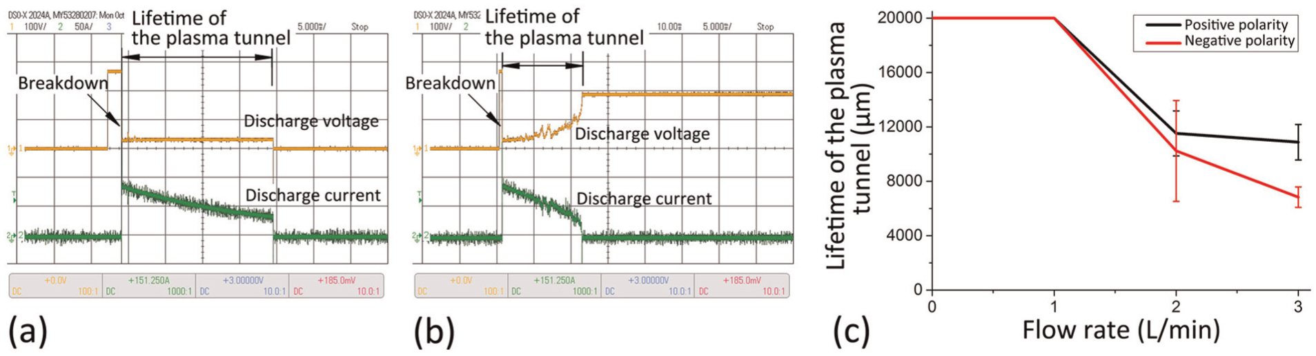
Discharge waveforms of the flow rates of (a) 0 L/min and (b) 3 L/min, and (c) effect of flushing on the lifetime of the plasma tunnel in the EAM experiment.
Polarity effects
Both the EDM and EAM processes stressed the importance of polarity effects. However, the EDM processes can adopt either positive polarity or negative polarity while all EAM processes mentioned above adopt positive polarity except ADM, the polarity of which is as yet unpublished.
The crater diameters of both the polarities of the EDM experiment were similar, but the distribution of elements was affected by the polarity. Moreover, the flow rate had no effect on the distribution of elements. The distribution of elements of the positive polarity craters was similar to that of the unprocessed workpiece surface; those of negative polarity were rich in Cu. Accumulated Cu was found on the craters, as shown in Figure 6. The accumulated Cu appears golden in color in Figure 6(a) and is indicated by white dots in Figure 6(c) by energy-dispersive spectroscopy (EDS) analysis. That could be attributed to the energy distribution of EDM. Although both the polarities are used in EDM processes according to materials, dielectrics and machining parameters, the anode always acquires more energy than the cathode.24,25 One symptom is that the crater of positive polarity is usually deeper than that of negative polarity. 26 The other symptom is that the material acquired by the cathode from the anode is more than that acquired by the anode from the cathode. The transformation of elements has been verified by a molecular dynamics simulation conducted at a micro scale. 27 These conclusions are suitable for the experimental results. Since the anode acquired more energy, more materials were ejected from the anode and adhered to the cathode. The tool was brass, so the crater of negative polarity contained more accumulated Cu than that of positive polarity, as shown in Figure 6.
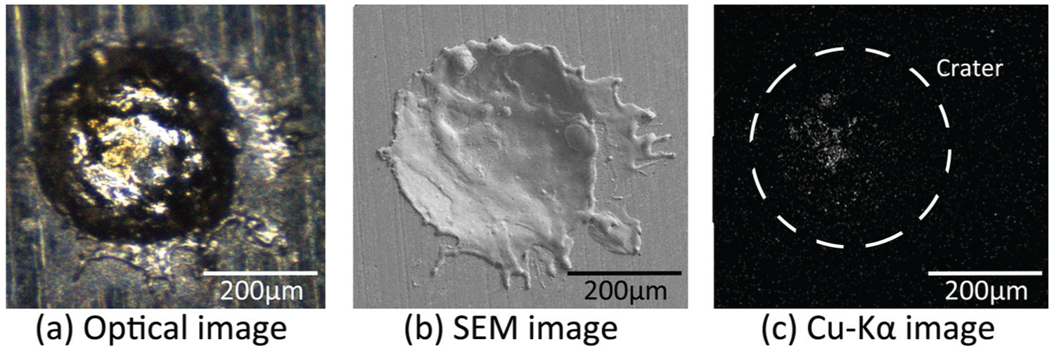
(a) Optical, (b) SEM and (c) EDS images of a crater of negative polarity.
The flow rate and polarity affected the distributions of elements in the EAM experiment, as shown in Figure 7. Figure 7(a) and (b) are craters of positive polarity while Figure 7(c) and (d) are craters of negative polarity with the flow rates of 0 and 3 L/min, respectively. The distribution of elements of tailing discharge craters is similar to that of the unprocessed workpiece surface, so the tails in Figure 7 are ignored.
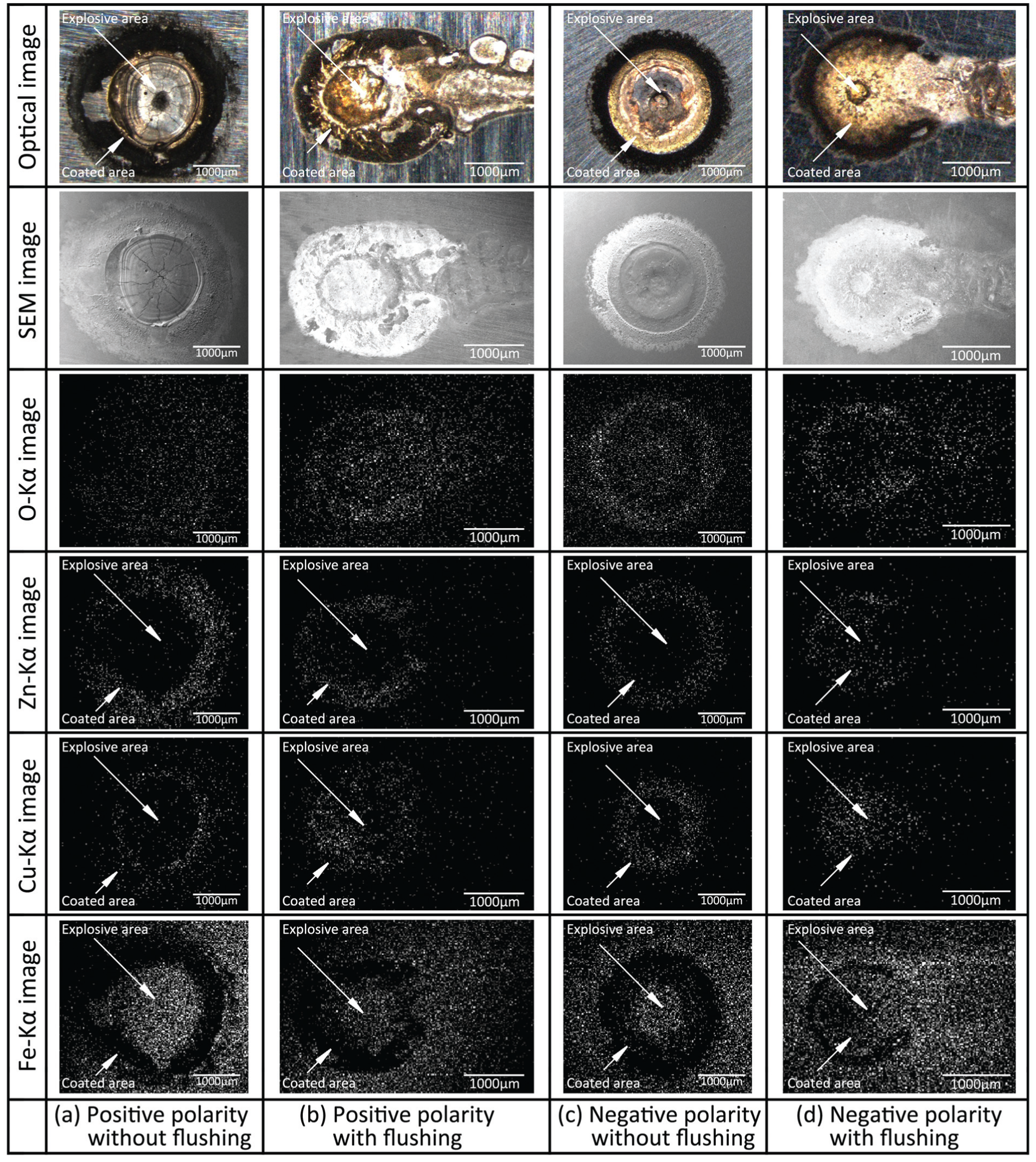
Craters of positive polarity with flow rates of (a) 0 L/min and (b) 3 L/min and craters of negative polarity with flow rates of (c) 0 L/min and (d) 3 L/min in the EAM experiment.
It was found in our previous studies that the crater geometry of EAM is seriously affected by polarity. Moreover, the long discharge duration of EAM has the characteristic of enhancing the polarity effects. Previous studies by our research group have verified the differences caused by extending the discharge duration. The evolution of the crater geometries of positive and negative polarities by extending the discharge duration is shown in Figure 8(a)–(f). The crater of positive polarity becomes bigger when longer discharge duration is adopted while the crater geometry is kept constant, as shown in Figure 8(a)–(c). The crater of negative polarity becomes shallower when longer discharge duration is adopted. Little material is removed and most of the material is re-solidified as white layer when the discharge duration is long enough for a certain peak current, as shown in Figure 8(f). The above mechanism is the reason that the TWR of EAM is low. Top views and profiles of craters of the previous experiment are shown in Figure 8(g)–(n). The peak current is 600 A, and the pulse durations are 100, 500, 2500 and 12,500 µs, respectively.
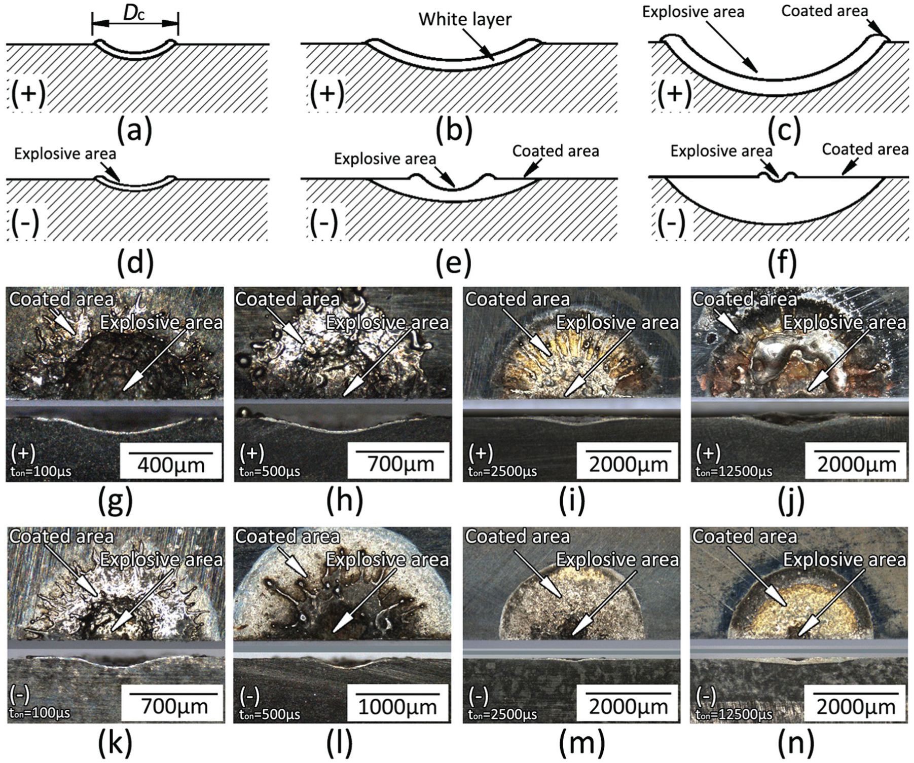
Evolutions of crater profiles of (a–c) positive and (d–f) negative polarities with the extending of discharge duration and top views and profiles of craters of (g–j) positive and (k–n) negative polarities with the extending of discharge duration.
The explosive area and the coated area were proposed based on the previous studies. The explosion of overheated material plays an important role in the erosion processes of EDM and EAM. The concave area formed by the explosion is named as the explosive area. Since the explosion expels the surface material, the explosive area is mainly constituted by the matrix materials of the workpiece, as indicated by arrows in Figures 7 and 8. In contrast, the coated area often lies around the explosive area and contains materials from the tool, the workpiece and the dielectric medium. It is supposed that the electrode material is melted and expelled and then adheres to the workpiece. The materials from the workpiece and dielectric medium are also involved in the formation process of the coated area. As a result, the coated area is formed. It has been found that the explosion of negative polarity is weakened with the growing of the discharge duration, and that the coated area takes up a larger proportion of the crater than the explosive area. The coated area contains more of the Cu and Zn expelled from the tool. The explosive area contains more Fe, less Cu and Zn because the explosion has expelled the coated surface. The crater of Figure 7(a) contains a large explosive area and a small coated area as shown in Figure 8(c). In contrast, the crater of Figure 7(c) contains a large coated area and a small explosive area as shown in Figure 8(c). The explanation for this is the typical energy distribution of EAM, as the anode acquires more energy than the cathode. The effects of flushing, as shown in Figure 7(b) and (c), are that the explosive areas of both the polarities were reduced. The flushing of the EAM experiment reduced the explosions of the tools and the workpieces and then reduced the MRR and TWR simultaneously. In agreement with the research22,28,29 about cryogenic cooling of the electrodes, reducing the crater diameter will lower both the MRR and TWR. The Ra of the machined surface will be reduced as well, because the Ra is determined by the crater diameter. 30 The above discussions can help to explain why only the proper flushing rate can improve the EDM and EAM processes. When the flow rate is too low, accumulations of debris and bubbles will be caused, which will deteriorate the machining process. In contrast, the MRR will be reduced if the flow rate is too high for the reduction of crater diameter and the breaking of plasma tunnels in EAM. Moreover, it is supposed that an excessive flow rate would reduce the discharge frequency by reducing breakdowns in EDM.
An interesting phenomenon was found that a crater of positive polarity usually had many tails, while a crater of negative polarity had only one tail, which agrees with the arc root moving theory, which holds that the movement of the anode root is discrete while the movement of the cathode root is continuous. 31 Also the length of the plasma tunnel of positive polarity was shorter than that of negative polarity, and the lifetime of the plasma tunnel of positive polarity was longer than that of negative polarity. This agrees with the conclusions of arc research, which holds that the root of cathode moves more easily and quickly than that of the anode.32,33
Conclusion
Two single-pulse discharge experiments covering EDM and EAM with different polarities and flow rates were designed and carried out. The plasma tunnels and craters were measured and studied. The effects of flushing on the fundamental phenomena of EDM and EAM including the tailing discharge craters, crater diameters, compressing and breaking of plasma tunnels and polarity effects were discussed. Main conclusions are as follows:
It is obvious in EAM that the plasma tunnel is lengthened and compressed by flushing. The plasma tunnel can be broken if the flow rate is high enough; however, the plasma tunnel in EDM is unaffected by flushing.
In EDM, the flushing has little impact on the polarity effect and element distribution. While in EAM, the polarity effect is strengthened and the element distribution is affected by flushing.
In EAM, the flushing reduced the crater diameters of both anode and cathode, which has the advantages of reducing TWR and Ra and the disadvantage of reducing MRR. The craters of EDM were unaffected by flushing.
Tailing discharge craters were found in the EAM experiment, while no tailing discharge crater was found in the EDM experiment. A crater of positive polarity has many tails while a crater of negative polarity only has one tail. Moreover, the root on the workpiece moves more easily and quickly when the polarity is negative. All of the conclusions above agree with the arc characteristics. The fact that EAM process adopts arcs while the EDM process adopts sparks to finish the machining process is verified.
Footnotes
Appendix 1
Declaration of conflicting interests
The authors declare that there is no conflict of interest.
Funding
This work is supported by grants from the National Natural Science Foundation of China (Grant No. 51375274), Scientific Starting Research Foundation for the Returned Overseas Chinese Scholars, Ministry of Education, China (2010), Research Fund for the Doctoral Program of Higher Education of China (Grant No. 20130131120077) and Independent Innovation Foundation of Shandong University (Grant No. 2012TS042).