
Abstract
In this study, a new kind of ultra-high-speed combined machining of electrical discharge machining and arc machining was developed. A rotating graphite electrode and a workpiece were connected to the negative and positive poles of the power supply, which consisted of a pulse generator and direct current power. Efficient electrode injection flushing and side flushing yielded a noncontinuous arc and achieved a maximum material removal rate of 12,688 mm3/min at a relative electrode wear ratio of 2.3% during quenched mold steel machining. The characteristics of the combined machining process were determined by studying the effects of flushing, rotation, peak current, and peak voltage on process performance, such as on the material removal rate and relative electrode wear ratio. The recast layer and surface defects were also investigated. The result shows that the novel combined machining process has great potential to reduce machining time.
Introduction
Electrical discharge machining (EDM) is a nonconventional technology developed since the 1940s. 1 EDM is widely used in manufacturing dies, molds, and parts with complex shapes because of its unique characteristics. EDM can machine any conductive material regardless of its hardness. In EDM, the tool electrode and workpiece have no direct contact; therefore, the forces applied to both the tool electrode and the workpiece are weak compared with those in traditional manufacturing processes. These extremely weak forces eliminate chatter and vibration during machining. 2
During EDM, heat energy is transformed from continuous pulse discharge. However, only a small portion of this energy (1%) is effectively used to remove electrodes, 3 and more than 90% of the heat is conducted into the workpiece and tool electrode. As to removal efficiency, the ratio of removal volume to the total molten volume is about 1%–10%, indicating that most of the molten material resolidifies in the crater.1,4 Thus, EDM efficiency is lower than the efficiency of high-speed machining, which has rapidly been developed in the aerospace and mold die industries and has largely replaced EDM in machining difficult-to-cut workpiece materials.5,6
Many studies have enhanced the removal efficiency of EDM. Using traditional sinking EDM to create a desired cavity usually requires special three-dimensional (3D) electrodes that are costly and time-consuming. To overcome these problems, simple frame and wire frame electrodes have been developed to machine workpieces and thus improve the material removal rate (MRR).7,8 A similar plate tool electrode driven by a computerized numerical control (CNC) EDM machine was used to machine a 3D cavity. The machining results indicated an MRR higher than that of the 3D tool electrode. The MRR achieved a maximum of 275 mm3/min at a current of 64 A. 9 However, such tool electrodes have long manufacturing time and cannot machine several 3D cavities with complex shapes. Thus, to reduce preparation time and cost, a bundled electrode consisting of many small hollow cell electrodes was created by Li and colleagues,10,11 who fabricated an approximate 3D end surface by adjusting the length of each electrode. The unique structure of this electrode and intensive inner flushing maximized the MRR to 789.8 mm3/min at a current of 127 A. However, this bundled electrode also took a long time to fabricate.
EDM milling has been proposed to minimize the time required to fabricate complex 3D tool electrodes. EDM milling is a promising machine process that uses a simple standard tool electrode and follows a programmed path to create a particular shape, as in traditional CNC milling. 12 Kunieda et al. 13 developed a method to improve EDM efficiency by supplying oxygen gas into the gap. The activated chemical reactions of oxygen increased the MRR. Kunieda et al. 14 also developed high-speed 3D dry EDM milling. Increasing discharge power density beyond a certain threshold increased the MRR because of the thermally activated chemical reaction between the workpiece and oxygen gas. The maximum MRR of dry EDM milling for quenched steel was almost equal to that of high-speed milling. However, the intense chemical reaction prevented material removal from being controlled and thus undermined accuracy. Yu et al. 15 investigated the capacity of dry EDM milling to machine cemented carbide material and found that the MRR of this technique during groove machining is about six times higher than that of oil EDM milling. However, because the melted material solidifies on the machined surface, dry EDM milling cannot achieve both the required MRR and the desired surface roughness. 16 The MRR of near-dry EDM improves only slightly.16,17 Han et al. 18 developed a high-speed EDM milling method using moving electric arcs obtained by connecting a rotating copper electrode and a workpiece to a direct current (DC) power supply with a peak current of 6 A. The experiment results indicated that the MRR was much higher than that of traditional EDM. However, the feasibility of this machining method in cases of high discharge energy was not indicated. During machining, high electrode speed with respect to the workpiece is necessary.
In this study, an ultra-high-speed combined machining of EDM and arc machining was developed to mill mold steel heat-treated to 51 HRC. In contrast to the moving electric arcs developed by Han et al., 18 a noncontinuous arc was obtained and used to remove materials. Efficient flushing and proper rotation of electrodes yielded an MRR of 12,688 mm3/min at a relative electrode wear ratio (REWR) of 2.3%. The effects of flushing, rotation, peak current, and peak voltage on process performance, such as on the MRR, REWR, and surface quality, were investigated. Experiment results show that this combined machining process reduces machining time.
Principle
The ultra-high-speed combined machining of EDM and arc machining is illustrated in Figure 1(a). The electrode and workpiece were connected to the negative and positive poles of the power supply, respectively; the power supply consisted of a pulse generator and DC power. The voltage/current signal in a single discharge is illustrated in Figure 1(b). When the pulse generator switched the power on, the electric field reached its highest strength in areas where the electrode surface was near the workpiece. Ignition occurred when the electrode was sufficiently close to the workpiece. Ignition abruptly formed a plasma channel. Adding current from the DC power to the plasma channel created an electric arc. The current from the pulse generator and DC power flowed through the plasma channel, inside which very high temperature (as high as 20,000 °C) 2 caused the material to evaporate and melt on both the electrode and workpiece. Flushing and electrode rotation caused the plasma channel to deionize and the pressure and temperature of the plasma channel to decline; thus, the dielectric fluid started ejecting and cooling the molten material. The dielectric fluid also flushed away debris in the gap and thus ensured machining stability. Video 1 (available online) shows the combined machining process.
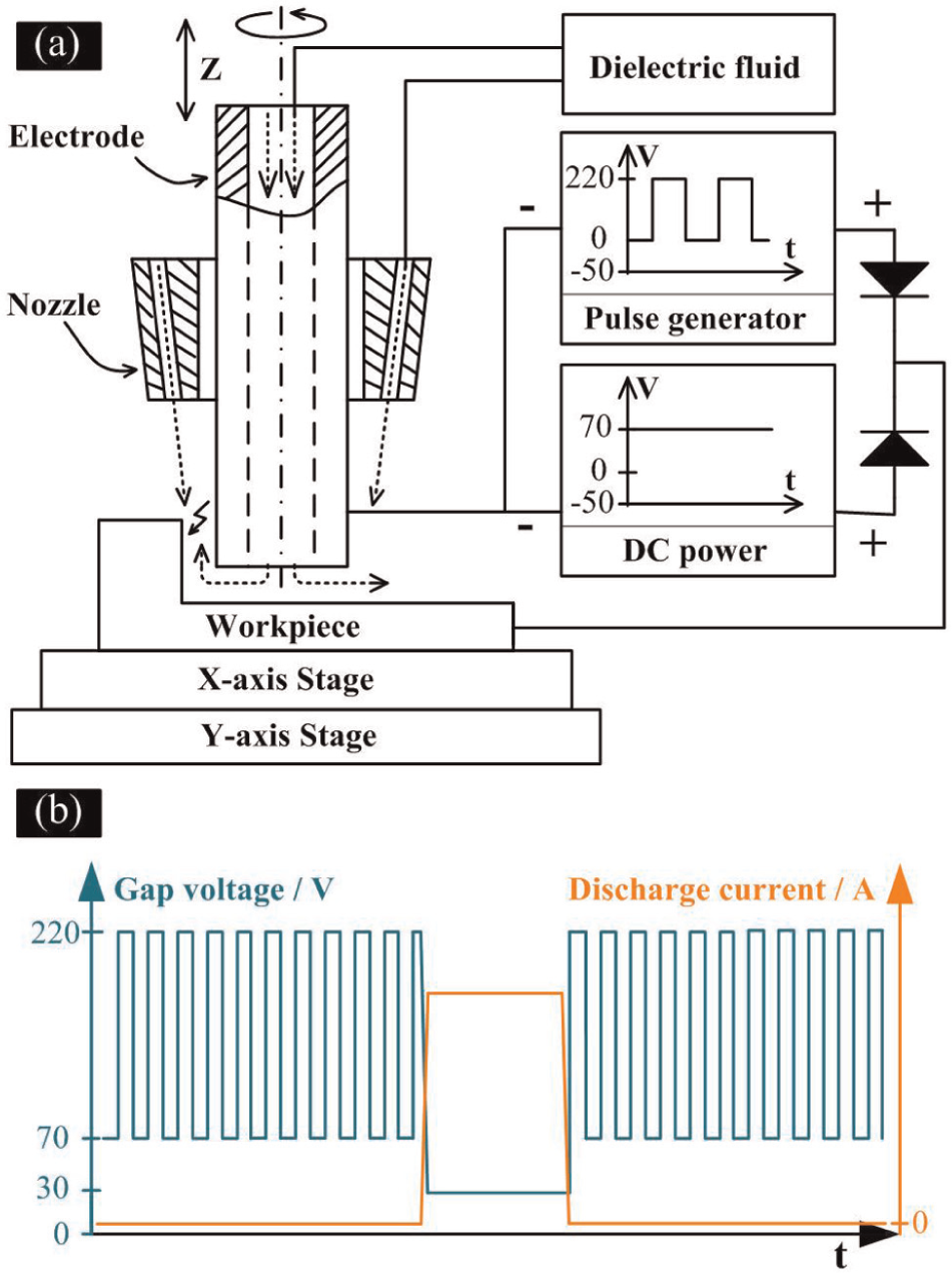
Illustration of (a) ultra-high-speed combined machining of EDM and arc machining and (b) voltage/current signal during single discharge.
Experimental equipment and setup
Experimental equipment
The machine tool used in the combined machining process is shown in Figure 2. A pipe graphite electrode was mounted on a rotary spindle fixed on the Z-axis stage. An alternating current (AC) inverter enabled the spindle to rotate from 0 to 3000 r/min. All the stages and the spindle were controlled by a control system consisting of a motion controller (Turbo PMAC; Delta Tau Data Systems, USA) and a control personal computer. Side flushing and electrode injection flushing were conducted by external circular flushing and internal tube electrode flushing, respectively. The pressure of the electrode injection flushing was adjusted by a pump controlled by the AC converter. A filter was used to clean the dielectric fluid before it flowed to the tank. The maximum peak voltage of the pulse generator was 220 V, and the peak current was 30 A; the voltage of the DC power was 70 V, and the maximum peak current was 700 A. These two types of power were isolated from each other by diodes.
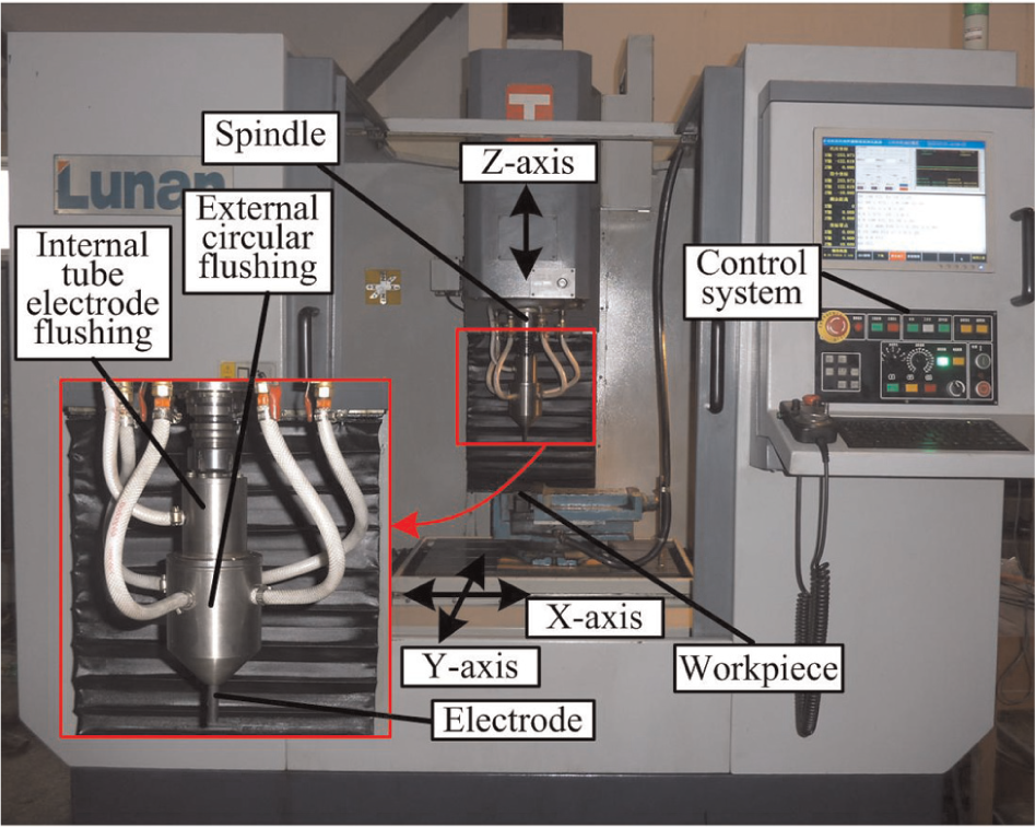
Photograph of the experimental machine tool.
The waveforms of the gap voltage and discharging current are shown in Figure 3. The normal discharge gap voltage was about 28 V. During the combined machining process, the average gap voltage, which reflected the discharging state, was collected and processed by the motion controller to determine the feed rate of the process.
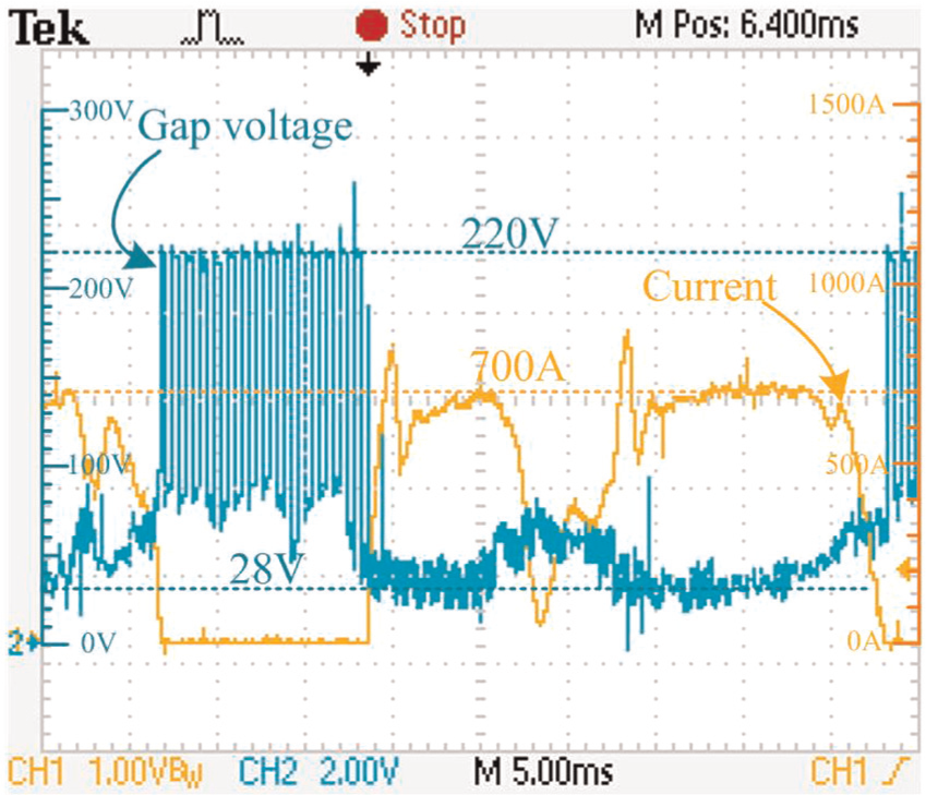
Waveforms of the gap voltage and current.
Experimental setup
The workpiece material was AISI H13 heat-treated to 51 HRC. The electrode was a pipe graphite electrode with an outer diameter of 10 mm and an inner diameter of 4 mm. Grooves were machined on the workpiece to determine the machining characteristics of the combined machining process under different conditions. The electrode moved toward the surface of the workpiece at 5 mm, and the workpiece then moved at a length of 50 mm, driven by the Y-axis stage.
The dielectric fluid was a water-based emulsion composed of 10 mass% emulsified oil (DX-1; Nanjing Special Oil Factory, China) and 90 mass% distilled water. The fluid had a conductivity of 37 µS/cm.
Comparison experiments were conducted to reveal the differences between electrode injection flushing and electrode suction flushing. Debris formed by exorbitant discharging current blocked the electrode because of the small inner diameter of the electrode. Thus, the peak current was set to a maximum of 230 A. A hole and a groove were machined under the same flushing conditions.
A precision balance (Sartorius BS224S) with an accuracy of 0.1 mg was used to measure the weight losses of the electrode and workpiece. MRR and REWR were then calculated. MRR was expressed as the ratio of the volume of the removed workpiece to the machining time
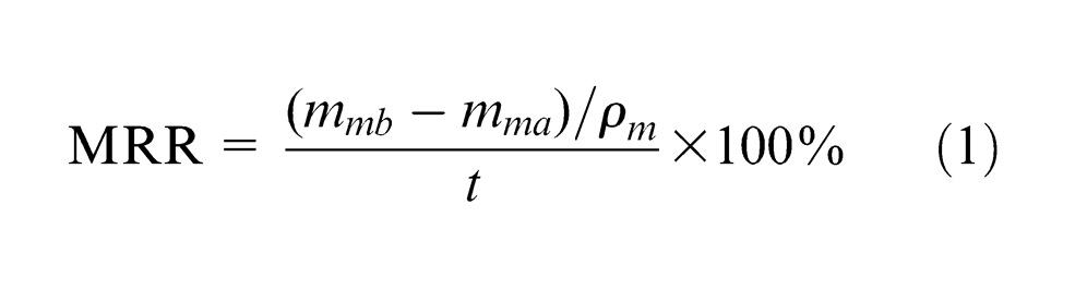
where
REWR was expressed as the volume percentage of the electrode wear relative to the removed workpiece
where
A scanning electron microscope (SEM; Hitachi S4800), energy dispersive spectrometer (EDS), and metallographic microscope (Nikon Eclipse ME600P) were used to examine surface characteristics after the combined machining process. The machining experimental parameters are listed in Table 1.
Machining parameters used in experiments.
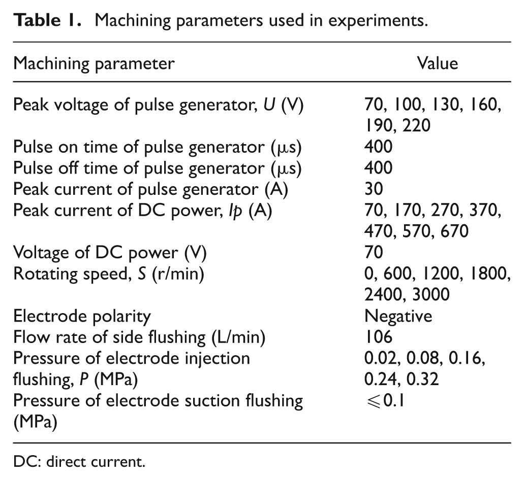
DC: direct current.
Results and discussion
Effect of machining conditions on process performance
Comparison experiments were conducted, and the machining parameters are shown in Table 2. Compared with arc machining alone, the combined machining process had a similar MRR but a low REWR (Figure 4). Furthermore, although the REWR of the combined machining process was slightly higher than that of conventional EDM, the MRR was much higher. This phenomenon can be explained as follows. During conventional EDM, only 1% of the energy is used to remove electrodes, 3 resulting in a lower MRR than that of the combined machining process. Compared with the gap of the combined machining process at a peak voltage of 220 V, that of arc machining at a peak voltage of 70 V was small. Debris became increasingly difficult to eject with a narrowing gap; debris accumulation in the gap increased the possibility of tool electrode shock caused by the debris and thus increased the REWR. Furthermore, both arc machining and the combined machining obtained energy primarily from the DC power and thus achieved similar MRRs.
Comparison experiment parameters.
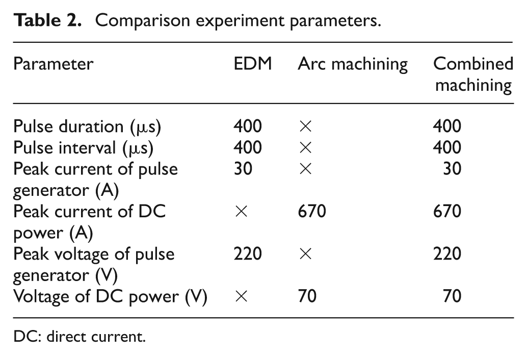
DC: direct current.
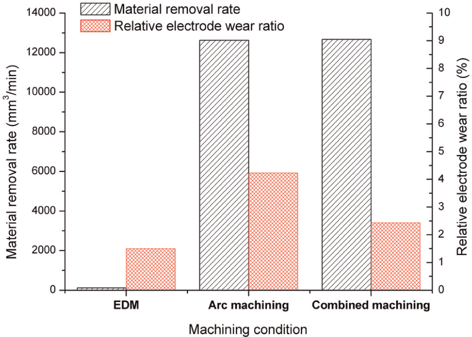
Result of comparison experiments with different machining conditions.
Effects of peak current on MRR and REWR
The effects of peak current on MRR and REWR are shown in Figure 5, which reveals that MRR increased with increasing peak current. A peak current of 700 A yielded an MRR of 12,688 mm3/min. The REWR only slightly changed and fluctuated at around 2.3% because the thermal energy density increased with increasing peak current. High thermal energy density increased the amount of materials that can be melted and removed from the workpiece and electrode during a single discharge. Thus, the MRR of high peak current was higher than that of low peak current. However, the increased electrode wear ratio only slightly changed the REWR regardless of the peak current.
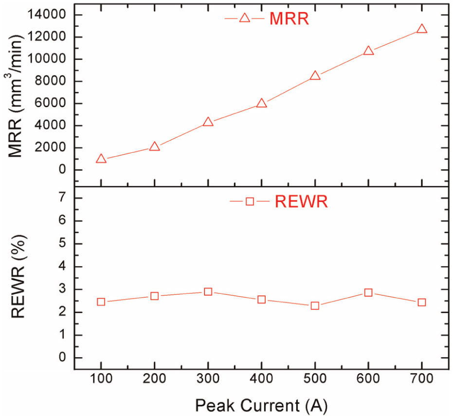
Effects of peak current on MRR and REWR (U: 220 V, P: 0.32 MPa, S: 3000 r/min).
Effects of peak voltage of pulse generator on MRR and REWR
The effects of peak voltage on MRR and REWR are shown in Figure 6. The REWR decreased with increasing peak voltage, whereas the MRR only slightly changed. The main discharging energy was supplied by the DC power, and the maximum discharging energy remained the same regardless of the peak voltage; thus, the MRR only slightly changed. During machining, the discharging gap increased with increasing peak voltage; with a small discharging gap, the electrode was shocked by debris. Therefore, the REWR of high peak voltage was lower than that of low peak voltage.
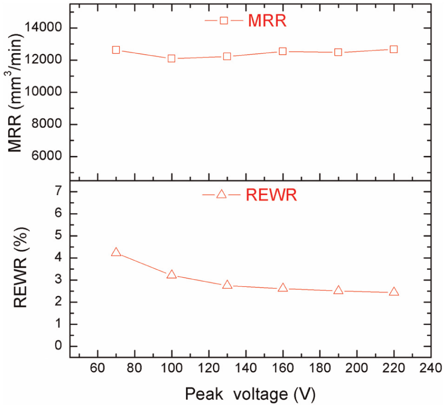
Effects of peak voltage on MRR and REWR (Ip: 700 A, P: 0.32 MPa, S: 3000 r/min).
Effects of flushing on process performance
Effects of electrode injection flushing and electrode suction flushing on process performance
During discharging, flushing the dielectric fluid benefits traditional EDM.2,19,20 The different machining effects with electrode injection flushing assisted by side flushing as well as electrode suction flushing assisted by side flushing during the combined machining process are shown in Figure 7(a) and (b), respectively. Electrode suction flushing created a better sidewall groove but a worse cylindrical boss-shaped workpiece drilling hole than electrode injection flushing. A part of the bottom surface of the groove was deeper than the rest of the surface, and the discharge crater significantly differed from the other (Figure 7(b)). Electrode injection flushing created a better groove bottom surface and cylindrical boss-shaped workpiece than electrode suction flushing. This phenomenon can be explained as follows. During the injection flushing, the fresh dielectric was supplied through the electrode, hence the breakdown strength was high, and the discharge gap was small, which caused good internal geometry and bottom surface. Then, the contaminated dielectric caused by the ablated particles decreased the breakdown strength and increased the discharge gap, thence the external diameter was large. During the suction flushing, the fresh dielectric was sucked into the electrode, thus the external diameter was small. Then, the contaminated dielectric with low breakdown strength increased the discharge gap, and therefore, the smaller remaining plateau and bad bottom surface were obtained.
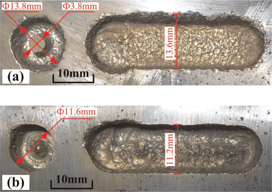
Different machining effects with (a) electrode injection flushing assisted by side flushing and (b) electrode suction flushing assisted by side flushing (Ip: 230 A, U: 220 V, S: 3000 r/min).
Comparison of electrode injection flushing and side flushing
Different cross sections and partial metallographic micrographs of the workpiece with different flushing methods are shown in Figure 8. The target diameter and depth of the bores were 10 and 4 mm, respectively. The effects of side flushing are shown in Figure 8(a). A huge undesired discharge crater was formed by a long arc at points (a)-(1), (a)-(2), and (a)-(3). The metallographic micrographs indicate the occurrence of huge cracks and blowholes and a recast layer with a thickness larger than 300 µm. In the normal discharging region, as shown at points (a)-(4) and (a)-(5), small cracks and a recast layer with a thickness smaller than 150 µm were found. These features were created because side flushing cannot reach the entire bottom of the hole and thus formed an undesired long arc (longer than 100 ms) without dielectric fluid flushing. The ejection of overheated molten material to the dielectric fluid formed cracks, blowholes, and a thick recast layer. In the normal discharging region, the arc was deionized by side flushing.
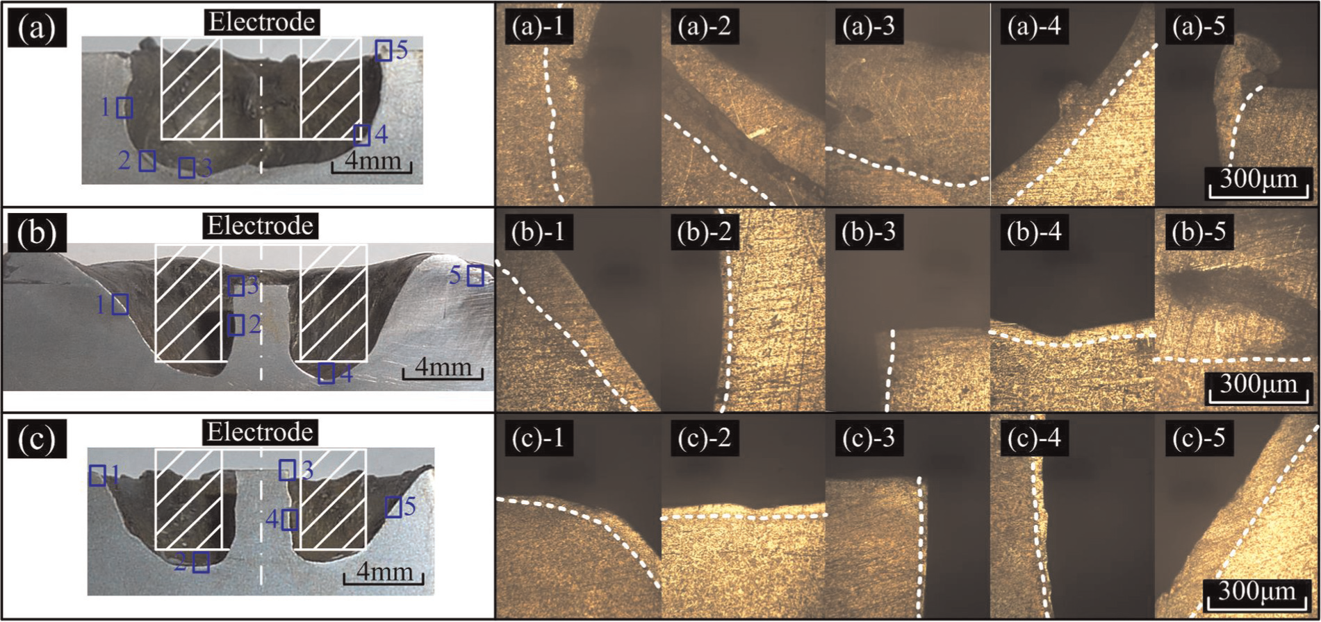
Cross sections and partial metallographic microscopes of the workpiece with (a) side flushing, (b) electrode injection flushing, and (c) electrode injection flushing assisted by side flushing (Ip: 700 A, U: 220 V, S: 3000 r/min).
The effects of electrode injection flushing are shown in Figure 8(b). Compared with side flushing, electrode injection flushing formed no huge cracks but solidified part of the molten material on the surface and created a blowhole at point (b)-(5). At point (b)-(1), the recast layer grew increasingly thick from bottom to top. The diameter of the cylindrical boss-shaped workpiece was 2.82 mm, and the recast layers were thinner than 50 µm at points (b)-(2) and (b)-(3). The recast layer at point (b)-(4) was thinner than that at point (b)-(1) because the arc plasma expanded by the flow of the dielectric fluid, the annulus between the cylindrical boss-shaped workpiece, and the electrode were smaller than those of the outlet. Thus, the flow velocity of the inlet was higher than that of the outlet, facilitating the flushing of the molten material near the inlet. Ejected molten material accumulated on the surface of the workpiece because flushing and cooling were not conducted.
The effects of electrode injection flushing assisted by side flushing are shown in Figure 8(c). Only little of the molten material solidified on the surface in this assisted method compared with mere electrode injection flushing. At points (c)-(2), (c)-(3), and (c)-(4), the recast layer was thinner than 50 µm, but that of point (c)-(5) was thinner than 150 µm. In contrast to the recast layer of point (b)-(1), that of point (c)-(1) was increasingly thinner from bottom to top because side flushing rapidly cooled the molten material ejected to the dielectric fluid to avoid solidification on the surface. At point (c)-(5), both side flushing and electrode injection flushing weakened and thus reduced the flushing and cooling effects and increased layer thickness. The bore diameter was 16.4 mm.
Effects of pressure of electrode injection flushing on MRR and REWR
The effects of the pressure of electrode injection flushing on MRR and REWR are shown in Figure 9. Increasing pressure from 0.02 to 0.08 MPa rapidly increased the MRR initially and slowly increased it thereafter. By contrast, the REWR rapidly decreased initially and then slightly changed at a pressure beyond 0.08 MPa. The reason may be that at a pressure smaller than 0.08 MPa, the plasma channel cannot efficiently deionize, and parts of the molten material solidified on the machined surface. Inefficient cooling would constantly heat the electrode. Increasing pressure enhanced the flushing and cooling effect and increasingly shortened the arc and thus increased the MRR and decreased the REWR. Increasing the pressure beyond 0.08 MPa increased both the MRR and electrode wear ratio and thus only slightly changed the REWR.
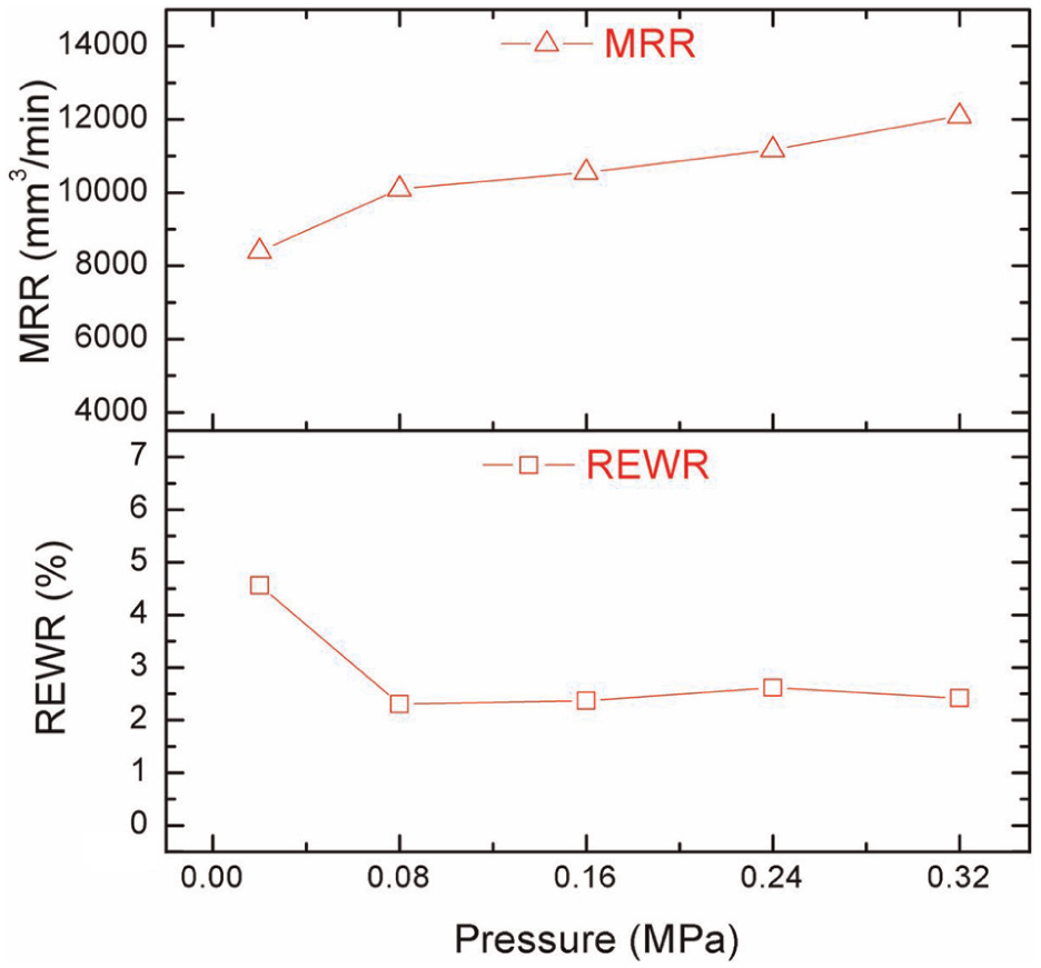
Effects of pressure of electrode injection flushing on MRR and REWR (Ip: 700 A, U: 220 V, S: 3000 r/min).
Effects of electrode rotation on process performance
The effects of rotation are shown in Figure 10. The effect of the rotation speed of 0 r/min is shown in Figure 10(a). The edge of the groove was worse than that of the groove for 3000 r/min (Figure 10(b)) because the arc freely expanded without electrode rotation during machining and the arc was deionized on both edges. The effects of rotation in the counterclockwise and clockwise directions at 3000 r/min are shown in Figure 10(b) and (c), respectively. The left edge of the groove was steeper than the right edge (Figure 10(b)), whereas the right edge of the groove was steeper than the left edge (Figure 10(c)). This difference may be attributed to the formation of an arc on one edge of the groove when the electrode moved along a certain direction; the arc expanded in the direction of the rotation through rotation and flushing. Thus, the edge of the starting point was better than that of the end point.
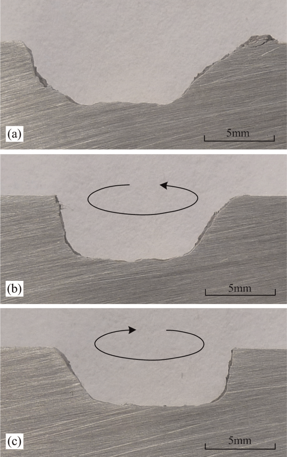
Effects of rotation with (a) 0 r/min, (b) 3000 r/min (anticlockwise direction), and (c) 3000 r/min (clockwise direction) (Ip: 700 A, U: 220 V, P: 0.32 MPa).
The effects of different rotation speeds on MRR and REWR are shown in Figure 11. The MRR initially decreased slowly with increased rotation speed; however, rotation speed beyond 1200 r/min slightly changed the MRR. The REWR only slightly changed. These results can be explained by the following. Increased rotation speed facilitated the deionization of the arc and reduced both the MRR and electrode wear ratio. A speed beyond 1200 r/min restricted the maximum energy of the single discharging arc and only slightly changed both the MRR and electrode wear ratio. Thus, the REWR only minimally changed.
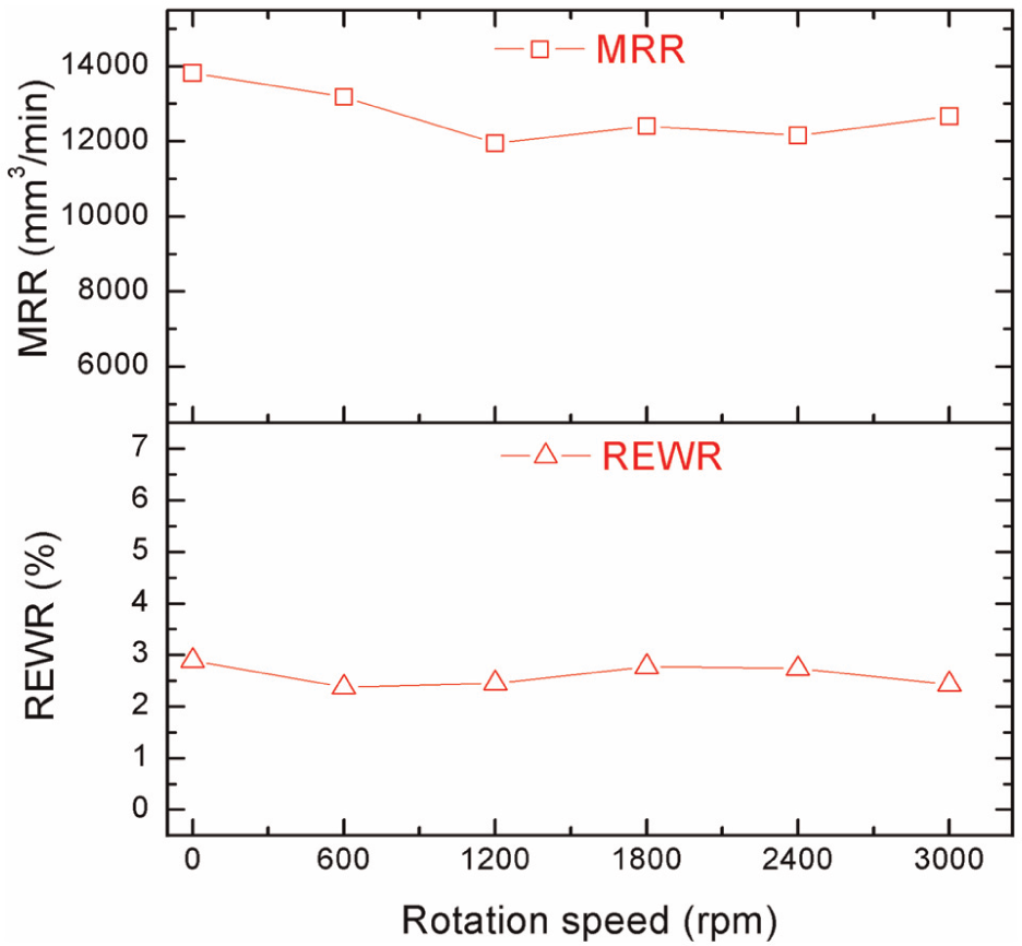
Effects of different rotation speed on MRR and REWR (Ip: 700 A, U: 220 V, P: 0.32 MPa).
Surface quality
Figure 12 shows a machining sample obtained by the combined machining process. The layer-by-layer method was used during the machining process. Combined machining with peak current of 700 A was performed for 25 min. A photograph of the machining sample is shown in Figure 12(a). Combined machining with peak current of 400 A was then conducted for 12 min. A photograph of the machining sample is shown in Figure 12(b).
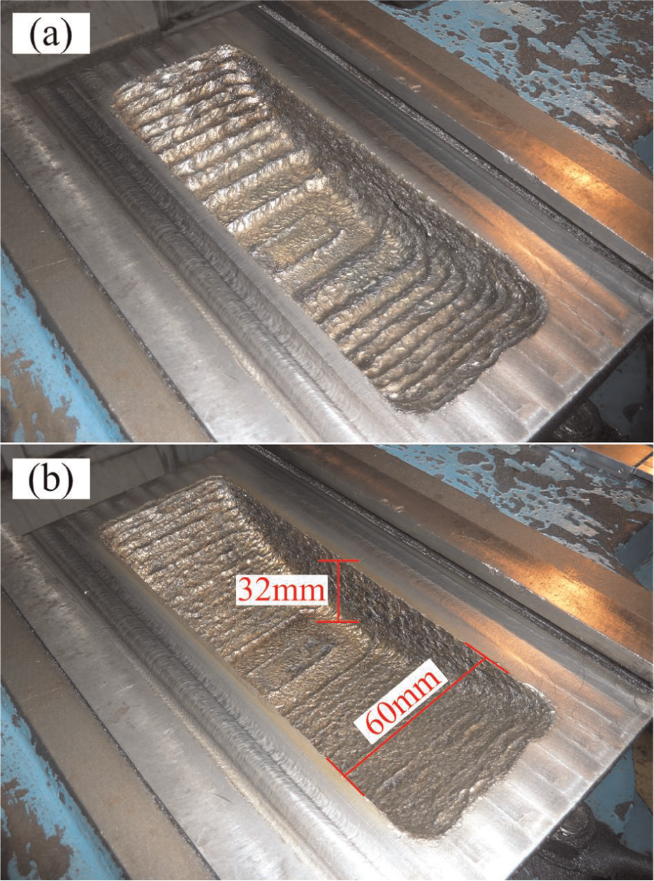
Photographs of the machining sample: (a) after combined machining with discharge current of 700 A and (b) after combined machining with discharge current of 400 A (U: 220 V, P: 0.32 MPa, S: 3000 r/min).
The original contour curve of the machined surface with peak current of 700 A is shown in Figure 13. The depth and diameter of the maximum crater were about 370 µm and 4.5 mm, respectively. SEM micrographs of the machined surface and cross section are shown in Figure 14(a) and (b), respectively. Many fish scale–like craters and droplets were observed on the machined surface probably because a part of the former crater was covered by molten material ejected by the latter discharge, as evidenced by the boundary of the two craters in Figure 14(b). The ejection of the molten material to the dielectric fluid led to the formation of cooled tiny liquid bubbles, parts of which stuck to the machined surface. Consequently, droplets with a diameter smaller than 17 µm formed on the surface.
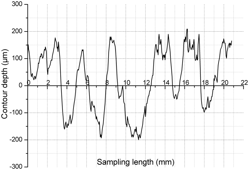
Original contour curve of the machined surface (Ip: 700 A, U: 220 V, P: 0.32 MPa, S: 3000 r/min).
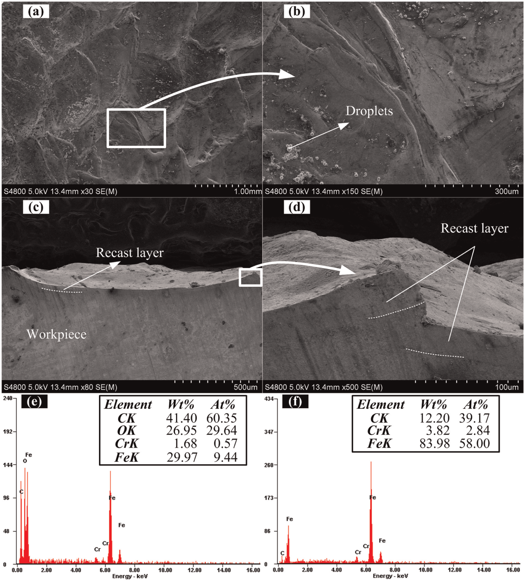
SEM micrographs of (a, b) machined surface and (c, d) cross section, and EDS results of (e) machined surface and (f) cross section of unmachined workpiece (Ip: 700 A, U: 220 V, P: 0.32 MPa, S: 3000 r/min).
SEM micrographs of the cross section of the workpiece are shown in Figures 14(c) and (d). A micrograph of the cross section of one crater is shown in Figure 14(c). The width of the crater was larger than the depth, and the recast layer was thinner than 100 µm because the arc plasma had a large diameter and the heat was thus distributed on a large area and could not reach deep into the workpiece. Efficient flushing removed the molten material and thus formed a thin recast layer. A cross-sectional photograph of the boundary of the two craters is shown in Figure 14(d). A part of the right crater was covered by the left one.
The EDS results of the machined surface in Figure 14(e) and the cross section of the unmachined workpiece in Figure 14(f) indicate that the proportion of carbon on the machined surface was much higher than that in the cross section of the unmachined workpiece. These results indicate a large amount of carbon deposits on the machined surface, which had a high proportion of oxygen. Oxidation reactions seem to have occurred between the material and oxygen during the combined machining process.
Conclusion
The ultra-high-speed combined machining of EDM and arc machining is introduced in this article. A rotating pipe graphite electrode was connected to the negative poles of a power supply consisting of a pulse generator and DC power. Several experiments were conducted to study the characteristics of the combined machining process. The following conclusions can be drawn from the results of the experiments and analysis.
The arc can be deionized by efficient electrode injection flushing assisted by side flushing and proper rotation. Workpiece materials can be removed by combined machining at an MRR of 12,688 mm3/min. Combined machining achieved a lower REWR than arc machining.
The MRR increased with increased peak current, whereas the REWR only slightly changed. The peak voltage affected the discharging gap, and increased peak voltage significantly reduced REWR.
Flushing significantly affected the combined machining process. The MRR of electrode suction flushing was minimal because of the electrode size. However, electrode suction flushing obtained higher dimensional accuracy than electrode injection flushing. Electrode injection flushing assisted by side flushing reduced the resolidification of molten materials. Increasing electrode injection flushing pressure increased MRR.
Electrode rotation restricts arc expansion. Rotation direction affected the direction of arc expansion. Suitable movement and rotation directions can be used to obtain desired steepness for edges.
Footnotes
Declaration of conflicting interests
The authors declare that there is no conflict of interest.
Funding
We would like to thank the Chinese National Natural Science Foundation (Grant No. 51275529), the Science and Technology Development Plan of Qingdao City (Grant No. 12-1-4-7-(2)-jch), the Taishan Scholar Construction Project of Shandong Province (Grant No. TS20110823), and the Fundamental Research Funds for the Central Universities (Grant No. 11CX06065A) for their support for this research.