
Abstract
Electrical discharge machining is one of the widely used noncontact-type advanced machining processes in which material removal takes place due to melting and vaporization by thermal energy of electric sparks. Electrical discharge machining has the capability of machining difficult-to-cut materials such as superalloys, advanced ceramics, and composites with complex shapes at both macro- and micro-levels. But its application is limited to electrically conductive materials. Other limitations include low material removal rate, high tool wear rate, recast layer formation, and geometrical inaccuracy in the form of taper and overcut. To overcome such limitations, the mechanism of electrical discharge machining has been combined with the mechanism of one or more other machining/physical/chemical processes. The mechanism of two constituent processes may be applied simultaneously or sequentially to constitute the hybrid machining process. It has been found that the performance of hybrid machining processes is better than the constituent processes. This article presents the comprehensive review of the research work carried out so far in the area of electrical discharge machining–based hybrid machining processes. It discusses about the experimental and theoretical studies of electrical discharge machining–based hybrid machining processes to elucidate the effects of various control factors or input parameters on process performances. This article includes modeling and optimization studies and discusses the future trend of the research work in this area.
Keywords
Introduction
The evolution of technology has put tremendous pressure on manufacturing industries to come out of the arena of conventional machining processes and develop the manufacturing processes that are able to machine extremely hard materials, and generate complex profile with high surface quality and geometrical accuracy. The development of unconventional machining processes (UMPs) took place to meet these challenges. A multitude of UMPs has been developed by researchers to fulfill specific objectives. These UMPs may be classified depending on the source of energy and the mechanism of material removal as shown in Figure 1. The electrical discharge machining (EDM) is such an UMP, which is widely used in the industries to machine electrically conductive materials. The brief description of EDM has been presented in the following section.
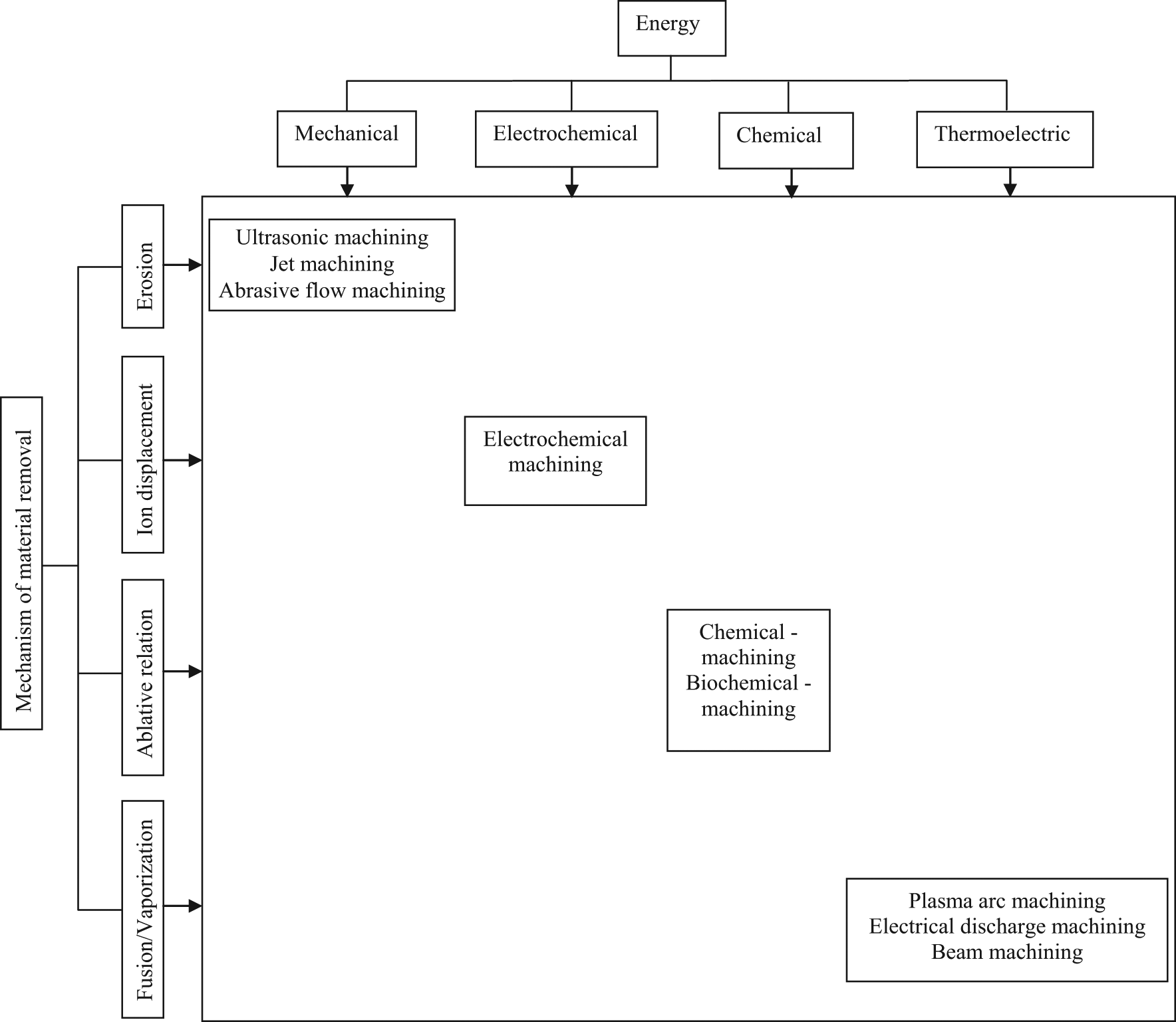
Classification of unconventional machining processes.
EDM
EDM is a thermoelectric process in which heat energy of a spark is used to remove material from the workpiece. EDM system consists of four basic components: (1) tool electrode and workpiece submerged into dielectric, (2) pulsed power supply system, (3) dielectric supply system, and (4) electrode feeding system, as shown in Figure 2. The power supply produces high-frequency pulsed voltage. The dielectric supply system includes the dielectric fluid, reservoir, filter, and pump to ensure proper supply of clean dielectric. The electrode feeding system maintains the predetermined gap between two electrodes through servo control mechanism.
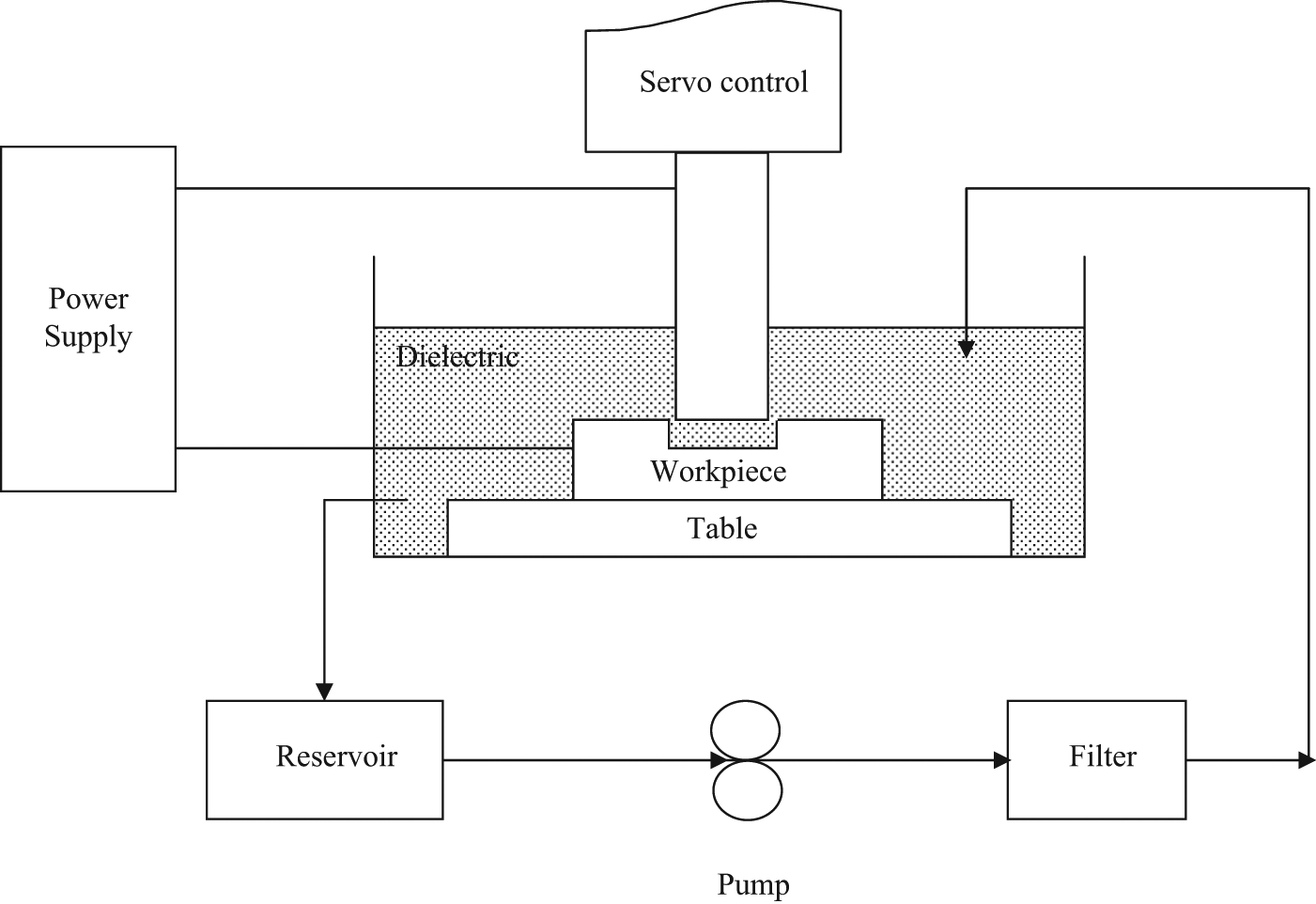
Components of EDM system.
Mechanism of material removal
The mechanism of material removal during EDM is as follows: (1) melting, (2) vaporization, and (3) thermal spalling, especially during machining of materials having high coefficient of thermal expansion, low thermal conductivity, and low ultimate strength. 1 The mechanism of spark generation in EDM is shown in Figure 3. As the voltage of suitable magnitude is applied between the two electrodes, the electrostatic force develops and the free electrons on the surface of cathode accelerate toward anode at a point where local gap between anode and cathode is minimum. While moving, electrons collide with the molecules of dielectric and in the process ionization of dielectric takes place, and thus more electrons and positive ions are generated. These electrons and positive ions further create electrons and positive ions by collision. Very soon the concentration of electrons and ions becomes very high, which is known as plasma. Plasma is a narrow column of ionized dielectric fluid molecules. The electrons with high velocity collide with the anode surface and their kinetic energy is converted into heat and local temperature rises to 8000 °C–12,000 °C. 2 Such a high temperature melts and/or vaporizes the work material. Similarly, positive ions collide with the cathode surface, resulting in melting and vaporization there. The pressure of plasma channel is so high that melted material does not get ejected. As soon as the pulse-off time starts, the plasma channel collapses, and due to shock wave and flowing dielectric, the melted material is removed.
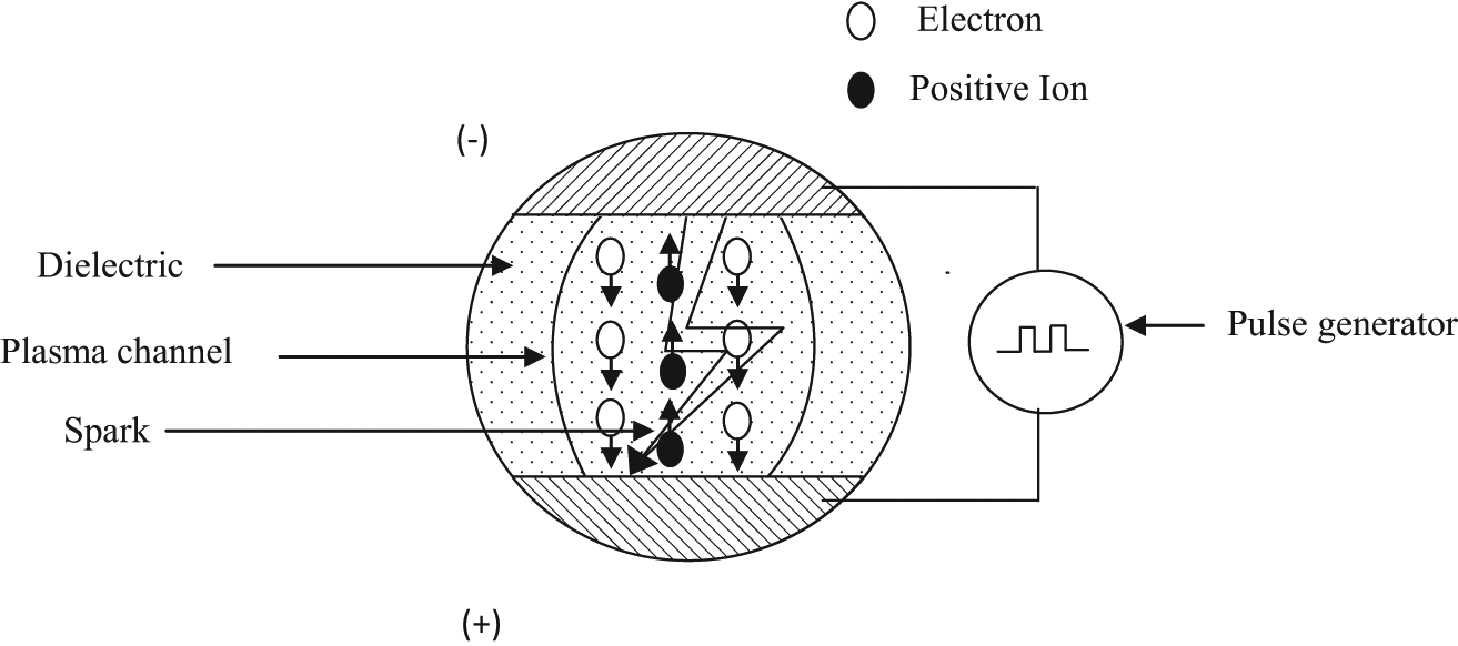
Mechanism of spark generation.
EDM variants
EDM can be used to perform different operations such as cutting, drilling, milling, and grinding as shown in Figure 4. The process may also be varied by changing the characteristics of dielectric medium. Different variants of EDM are briefly described below.
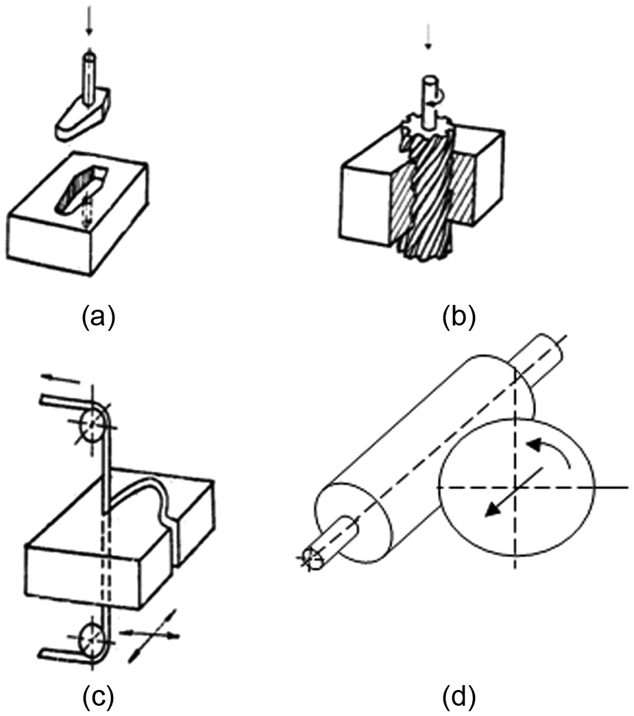
EDM variants: 3 (a) sinking, (b) drilling, (c) cutting, and (d) grinding.
Sinking EDM
In sinking EDM, the required shape is formed negatively in the workpiece with a tool having the exact replica of the feature to be produced. In sinking EDM, the relative speed between the tool and workpiece is coincident with the penetration speed in the workpiece. 3 This process has wide industrial applications in die manufacturing industry, wire drawing industries, and so on.
Drilling EDM
In drilling EDM, a rotating cylindrical-shaped electrode is fed toward the workpiece. This process is used to create blind or through holes of circular or some other cross section.
Milling EDM
In milling EDM, a rotating toothed wheel, acting as tool electrode, is traversed along a predefined path to machine large surface area. Milling EDM is a potential candidate for creating complex three dimensional (3D) profile and machining low conductivity ceramic materials such as SiC, B4C, and Si3N4. 4
Cutting EDM
There are several variants of cutting EDM such as wire cut EDM (WEDM), disk cutting EDM, and ribbon cutting EDM. In WEDM, the machining takes place due to a series of discrete sparks occurring between the workpiece and the wire (generally 0.05–0.3 mm in diameter) separated by a stream of dielectric, which is continuously fed to the machining zone. This process is used to create complex shapes especially in difficult-to-cut materials. 5 In disk cutting EDM, a rotating or stationary disk is fed toward the workpiece and the material is removed by melting and vaporization. The disk cutting EDM is used to cut off or notch the difficult-to-cut material.
Electric discharge grinding
Electric discharge grinding (EDG) is the process that works on the same principle as EDM. A rotating wheel, made of electrically conductive material, is used as a tool electrode. The complete workpiece and part of the grinding wheel are immersed in the dielectric. The mechanism of material removal is similar to conventional EDM. The rotary motion of the wheel enhances the molten material ejection.
Micro-EDM
Micro-EDM (µEDM) is a technology that is used to create the features which ranges from 1 µm to less than 1 mm. The mechanism of material removal in µEDM is same as that of conventional EDM or macro-EDM, except that the plasma channel radius in µEDM is much smaller than the macro-EDM. Special EDM components in terms of pulse generator and high precision systems are required in µEDM. Since the discharge energy is quite low and there is no contact between the electrodes, the process can be used to create very precise micro-features. 6
Powder mixed EDM
Powder mixed EDM (PEDM) is a process in which a suitable conductive powder is mixed into the dielectric. When a voltage of suitable magnitude is applied across the electrodes, the powder fills up the spark gap and bridges the gap between the tool electrode and the workpiece. Due to this bridging, the gap voltage and insulating strength of dielectric fluid reduce and discharge frequency increases which results in faster erosion. The powder particle enlarges the plasma channel which ultimately results in uniform distribution of spark. 7
The copper, graphite, titanium, and silicon powder are generally added in the dielectric. The concentration and size of the powder used play a vital role to improve material removal rate (MRR), tool wear rate (TWR), and surface integrity. PEDM is also used for surface modification to achieve desired hardness. Chemical and corrosion resistance surfaces 8,9 used graphite nano-powder during µEDM of cemented tungsten carbide and found that surface integrity in terms of surface finish and crater distribution has improved with the addition of nano-powder. Jahan et al. 10 observed similar improvements in surface integrity during µEDM of tool steel using graphite powder. Furutani et al. 11 added titanium powder in the dielectric and found that due to formation of TiC, the surface of workpiece hardened. Prihandana et al. 12 found that suspension of nano-powder reduces the surface crack.
Dry EDM
Dry EDM is a variant of EDM, in which conventional mineral oil–based dielectric is replaced by a high-pressure gas. Dry EDM is a “green” machining process since it does not generate toxic fumes and there is no fire hazard. Dry EDM is characterized by low TWR and high surface integrity in terms of lower residual stresses and thin recast layer. The major disadvantages include low MRR and process instability. 13,14
EDM applications
EDM process is most widely used in the mold-making, tool, and die industries. 15 It has wide applications in the manufacturing of prototypes and products in the aerospace, automobile, surgical components, and electronics industries in which production quantities are relatively low. 16 EDM plays a significant role in machining of superalloys such as Inconel718, used in the aerospace industry. Besides metals and alloys, it is also used to machine metal matrix composites (MMCs) and conductive ceramics which find wide applications in automobile industry, cutting tools, dies, and other special tools. 17,18 One of the novel applications of EDM is to alter the metallurgical and physicochemical nature of the surface by using a powder-metallurgy processed electrode. 19 EDM is used to remove broken taps and drill. WEDM is most widely applied in the manufacturing of the stamping and extrusion tools and dies, fixtures and gages, prototypes, aircraft and medical parts, and grinding wheel form tools. The silicon wafers used in the electronic industry are cut by WEDM. 20 WEDM is also useful in cutting fine details in prehardened stamping and blanking dies. EDG is used in the manufacturing of polycrystalline diamond (PCD) cutting tools. 21 EDG has also been used in the removal of cusps and fitting of a pair of dies. 22 µEDM is widely used to create micro-features in nozzles, orifices, and dies with dimensions ranging from a few micrometers to hundreds of micrometers. 23 A shaft of less than 5 µm diameter, prepared by µEDM, has been reported. 24 The hole in oblique plane can easily be drilled by µEDM. µEDM milling has been used to produce the micro-components such as micro-compressor and turbine impeller as shown in Figure 5. 25 The wire electro-discharge grinding (WEDG) 26 finds applications in the manufacture of the micro-probes, micro-tools, micro-shaft of gears, ejector pins in forming tools, pin electrode for micro-electric discharge drilling, electron emitter, and needle-shaped parts. 27,28 Electrical discharge texturing is used for the texturing of cold rolled steel and aluminum sheets. Trajectory EDM technique, which facilitates the electrode to move along a smooth trajectory, has been applied to manufacture curved hole for water channel in the molds. 29
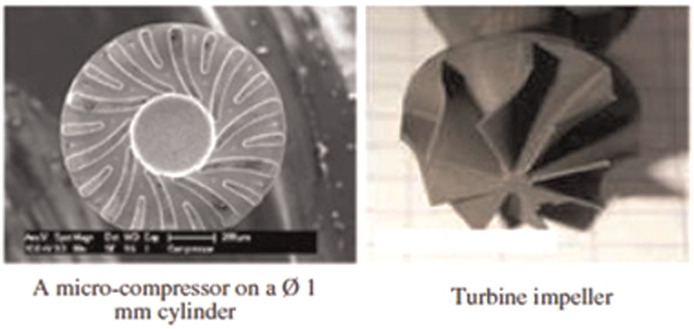
Micro-components made by milling EDM. 25
Limitations
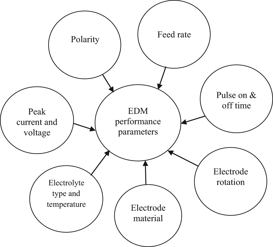
Being a thermal energy–based process, the performance of EDM depends on the thermal properties such as melting point, thermal conductivity, and to certain extent physical properties such as density. By virtue of the process, EDM can be applied to machine only electrically conductive materials. To apply EDM, the electrical conductivity of workpiece should be more than 100 Ω cm, 30 although researchers are trying to overcome this limitation by using assisting electrode and doping techniques. 31,32 Kucukturk and Cogun 32 developed an innovative method for machining nonconductive ceramic workpieces using EDM. They concluded that nonconductive workpieces such as Al2O3, ZrO2, SiC, B4C, and glass can be effectively machined using EDM by applying a conductive layer coating. The numerous research works done to investigate the effects of various control factors on quality characteristics (Figure 6) conclude that EDM results in low MRR, high TWR, formation of recast layer, and requires high specific energy. The typical MRR during EDM is 60 times less than the conventional milling. 3 EDM process is not able to reproduce sharp corners due to high tool wear. Sometimes, the application of EDM is restricted due to formation of recast layer on the workpiece surface. The recast layer results in hard and brittle surface and decreases the fatigue strength of material due to presence of micro-cracks, micro-voids, and residual tensile stresses. 33 Furthermore, overcut and taper of the electrical discharge machined geometry require careful design of the tool.
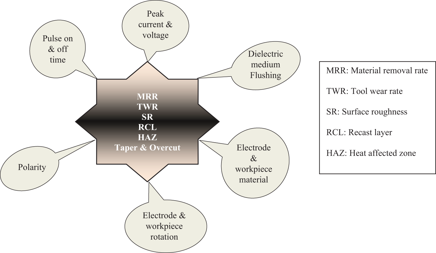
Process performances in EDM.
Hybrid machining processes
Despite tremendous research, the UMPs have their own limitations regarding MRR, high specific energy consumption, surface integrity, and geometrical inaccuracy. To offset these limitations, now researchers are focusing on hybrid machining processes (HMPs). The HMP is a concept that combines two or more different machining/physical/chemical processes in a simultaneous/sequential manner in order to accommodate the advantages and offset the limitations of constituent processes. It has been found that the performance of HMP is better than the individual constituent processes. The HMPs may be broadly classified into two categories: (1) primary HMPs (PHMPs) and (2) secondary HMPs (SHMPs). PHMPs are those processes where all the constituent processes simultaneously affect the machining zone and significantly contribute for the material removal mechanism, whereas in SHMPs only one process dominate for the material removal mechanism and others are just the assisting ones. 34 The PHMPs can further be subclassified into abrasion-assisted HMPs 35 and hybrid electrical–chemical machining process. Also, SHMPs can be subclassified into laser-assisted HMPs (LAHMPs), ultrasonic-assisted HMPs (UAHMPs), and magnetic force–assisted HMPs. These classifications are shown in Figures 7 and 8, respectively.
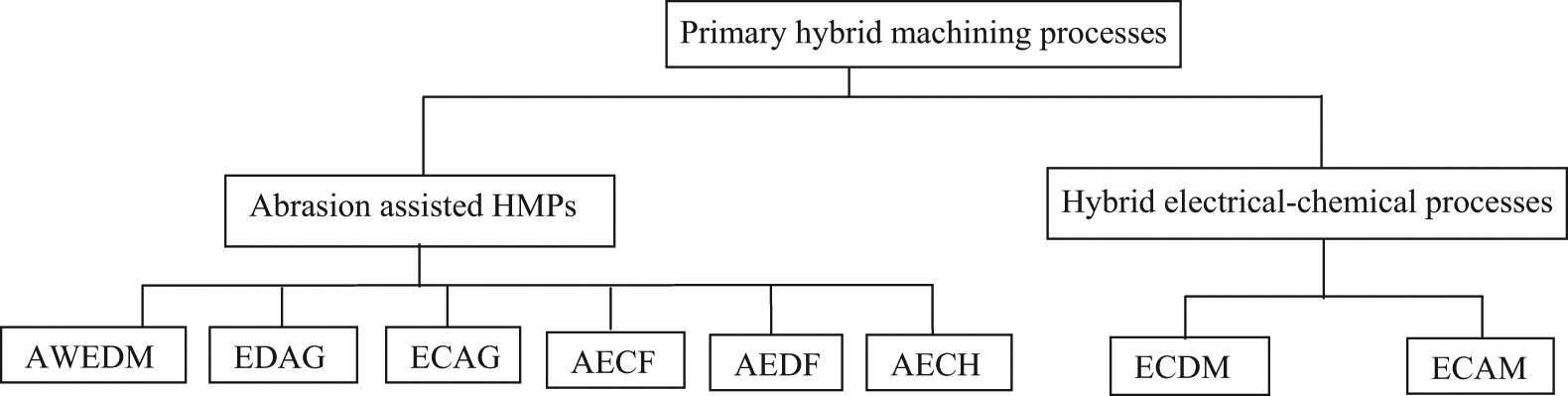
Primary hybrid machining processes.
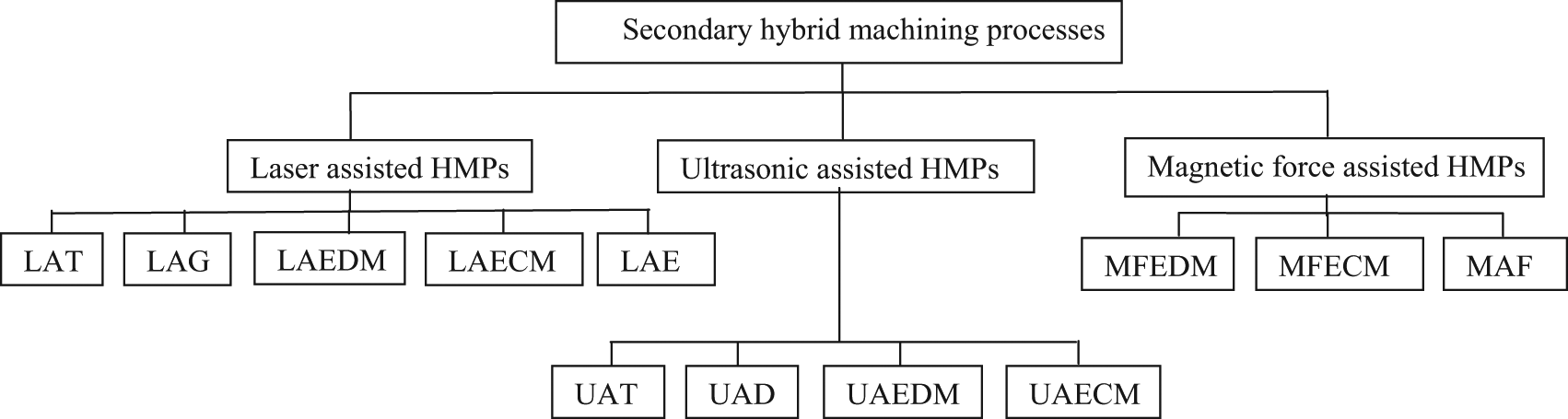
Secondary hybrid machining processes.
Abrasive WEDM (AWEDM) process, which utilizes the wire electrode embedded with abrasive, helps to minimize the recast layer and at the same time enhances the MRR. 36 Electrochemical abrasive grinding (ECAG), an HMP of electrochemical machining (ECM) and grinding, is suitable for machining sintered carbides and creep resisting alloys. 37 The performance index of ECAG is better than ECM due to combined action of micro-cutting, electrochemical action, breakdown of surface oxidation layer, and improved electrolyte circulation. Abrasive electrical discharge finishing (AEDF) and abrasive electrochemical finishing (AECF) are HMPs in which free abrasives are mixed with dielectric/electrolyte. The material is removed due to combined effect of mechanical action and electrical/electrochemical action. 35 Abrasive electrochemical honing (AECH) combines the fine abrasive action of honing with electrochemical action. AECH is much faster than conventional honing. 38
LAHMP is an innovative technology used to shape difficult-to-cut materials. LAHMP combines laser beam machining (LBM) with conventional and unconventional machining methods such as turning, milling, EDM, ECM, and etching. The laser is used as a heat source to soften the surface layer of the workpiece during machining of high wear resistance materials. Laser-assisted turning (LAT) has found to reduce the surface roughness (SR), tool wear, and cutting forces during machining of ceramics and composites. 39,40 In laser-assisted grinding (LAG), the machining zone is preheated by laser beam, before actual grinding and thus reduces the temperature gradient and surface damage. 41 In laser-assisted ECM (LAECM), the laser beam accelerates the electrochemical dissolution and hence enhances the MRR. 23,42 The laser-assisted etching (LAE) has been used for fabrication of superconductive ceramics and semiconducting devices. 43
UAHMP is achieved by imposing high-frequency, low-amplitude ultrasonic vibration to the cutting tool/medium during conventional and unconventional machining. Ultrasonic-assisted turning (UAT), which is used for machining of tough and brittle materials, improves the SR, tool life, and reduces the cutting forces as compared to conventional turning. 44 Ultrasonic-assisted drilling (UAD) helps to reduce the chip size and variation in torque, and thus improves the hole quality in terms of circularity, cylindricity, and SR as compared to conventional drilling. 45 Ultrasonic-assisted ECM (UAECM) is achieved either by imparting ultrasonic vibration to the tool or by immersing electrochemical cell into ultrasonic bath. UAECM demonstrates better performance due to increase in surface dissolution and electrochemical reaction. 46
Magnetic field–assisted ECM (MFECM) helps to achieve small gap with stable ECM action. 47 Magnetic abrasive finishing (MAF) is a super finishing operation in which abrasive particles are forced against the workpiece surface with the help of magnetic field. This process can be used to produce the surface finish of few nanometers on flat as well as curved surface. 48
Remarks
EDM is a big boon to the manufacturing industries. The biggest strength of EDM lies in its ability to machine any electrically conductive material irrespective of its hardness and strength. Since the process is independent of mechanical interaction, problems of vibration, chatter, and so on are eliminated and it is ideally suitable to machine thin and fragile components. With numerous EDM variants, it is possible to machine almost any kind of complex geometry. The EDG has replaced conventional grinding for machining PCD tools. The large surface area components having low electrical conductivity can now be machined effectively using milling EDM. The milling EDM could be a supplement to sinking EDM as well as conventional milling. WEDM has been widely accepted in the modern tooling industries. Besides micro-holes and micro-shafts, µEDM can be used to create complex 3D micro-profiles. EDM has expanded its arena as material addition process by using suitable additives, but still a lot of research work is required to make it industrially applicable. The thermal dependency of the process requires careful selection of process parameters to avoid thermal damage. The surface damage in EDM may be of the order of 125 µm, which is considerably higher than that produced by conventional machining and some of the other UMPs such as ultrasonic machining (USM), abrasive jet machining (AJM), ECM, and chemical machining (CHM). Since the performances of HMPs have been found to be better in comparison to constituent processes, the disadvantages of widely applied EDM process such as low MRR, tool wear, heat-affected zone, and recast layer formation may be removed or reduced by EDM-based HMPs (EHMPs).
EHMPs
EHMPs combine EDM and other conventional/UMPs or physical/chemical processes such as grinding, ECM, LBM, USM, and magnetic field. On the basis of the reported works, the classification of EHMPs is shown in Figure 9. This section provides the description of different EHMPs regarding the need, constructional details, working principle, mechanism of material removal, and applications.
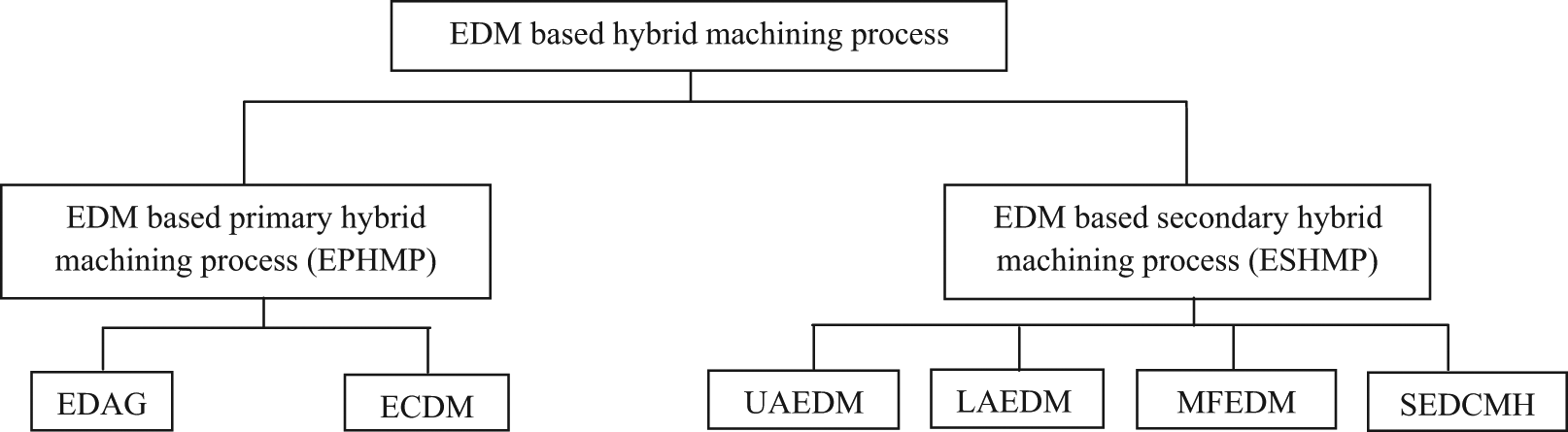
EDM-based hybrid machining processes.
EDM-based PHMPs
EDM-based PHMPs utilize the thermal effect of EDM and mechanical and electrochemical effects of grinding and ECM, respectively, in a simultaneous manner to enhance the process performances.
Electrical discharge abrasive grinding
The grinding of advanced materials is very difficult by conventional techniques due to their improved mechanical properties, for example, the grindability of MMCs still remains a challenge due to its hard reinforcement and hybrid nature of the constituents. It often results in poor surface quality (surface damage) in the form of surface cracks/residual stresses and requires frequent truing and dressing due to clogging of grinding wheel. Few researchers 49 –52 have studied the grindability of MMCs and tried to suggest optimum processing regime for improving the grinding performance, but their efforts could not overcome the above limitations up to the major extent.
EDM is suitable for machining of advanced materials, which are difficult to grind but results in low MRR. The limitations of both the processes, that is, poor grindability for advanced material and low MRR of EDM, can be overcome by combined process of EDM and grinding. Electrical discharge abrasive grinding (EDAG) utilizes the synergistic interactive effects of the conventional grinding and EDM. In this process, metal-bonded abrasive grit wheel is used in place of a simple electrically conductive wheel used in EDG. The whole workpiece and part of the wheel is submerged in the dielectric, and the spark is generated between the metal bond and the workpiece (Figure 10). The principle of spark generation in EDAG is similar to that of EDM. 53 Sparking occurs between the metal bond and the workpiece while the abrasive grains do the grinding action. In EDAG, the grain protrusion height Ph and interelectrode gap gw (Figure 10(b)) are very important parameters, which significantly affect the performance parameters as these directly control the depth of penetration. Here, the role of spark can be visualized in three ways: 54 (1) the sparking continuously does in-process dressing of grinding wheel so that active grains are continuously exposed to the work surface and wheel also does not clog, (2) the workpiece surface is softened by the spark so that it is easily machined by the abrasive grains, and (3) the spark substantially removes the material through melting and vaporization. EDAG can be operated in three different configurations, 55 that is, surface EDAG, cutoff EDAG, and face EDAG. Surface EDAG is used to machine flat surfaces by using periphery of grinding wheel which rotates about a horizontal axis. Cutoff EDAG is used to cut workpiece into pieces by using very thin wheel. Face EDAG is performed using flat face of the grinding wheel. The grinding wheel rotates about vertical spindle axis and is fed in a direction perpendicular to the machine table. Figure 11 clearly depicts various control factors and process performance parameters in EDAG. If the abrasive used is diamond, then EDAG is known as electric discharge diamond grinding (EDDG).
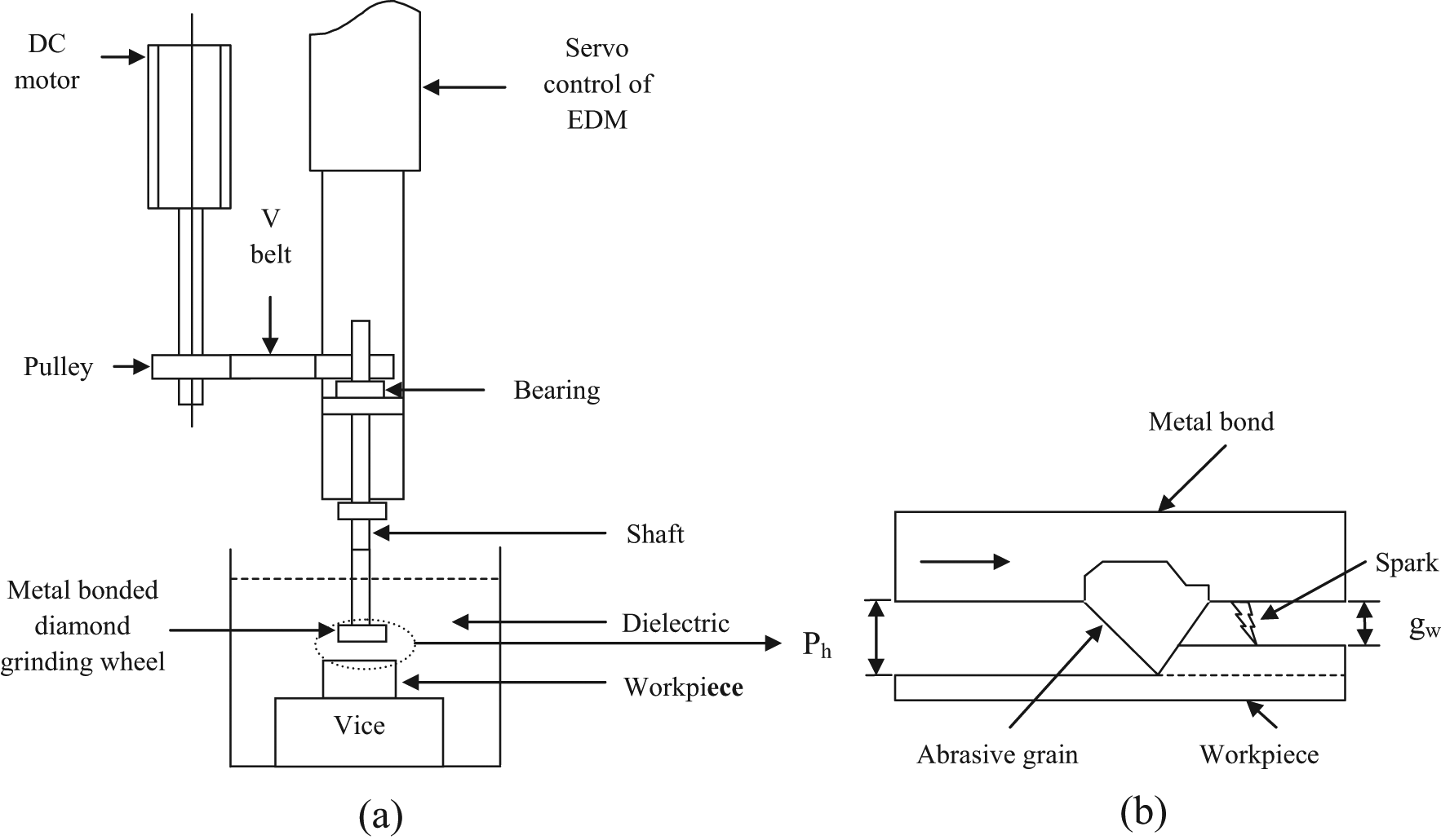
Electrical discharge abrasive grinding: (a) schematic diagram of machining setup and (b) schematic representation of wheel–work interface.
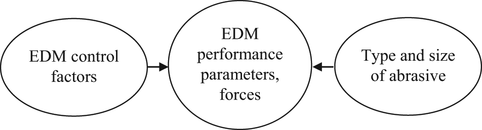
Process performances in EDAG.
EDDG is used for machining of cermets and superalloys. This process can be used for dressing/truing of metal-bonded abrasive wheel. 53
Electrochemical discharge machining
ECM is a process of anodic dissolution of electrically conductive workpiece by high current flowing through an electrolyte between shaped tool and workpiece. 56 Akin to EDM, the application of ECM is limited by electrical conductivity constraint. The electrochemical discharge machining (ECDM) has the potential to overcome this limitation. ECDM combines the features of both EDM and ECM and is generally used for the machining of nonconductive materials. This process has been given different names by different researchers, such as ECDM, electrochemical arc machining (ECAM), electrochemical spark machining (ECSM), and spark-assisted chemical engraving (SACE).
Figure 12 shows the typical arrangement of ECDM system. The system consists of a tool electrode, counter electrode, and power supply system, which generally supply constant direct current (DC) voltage and electrolyte. The tool electrode is dipped a few millimeters into the electrolyte. The counter electrode is far away from the tool electrode and has a much larger surface than tool electrode. As the voltage is applied across the electrodes, the electrolysis of electrolyte takes place and hydrogen gas bubbles are formed at the cathode and oxygen at the anode. With the increase in voltage, the bubble density and mean radius increase. When the voltage is increased above a critical voltage, bubbles coalesce into a gas film around the tool electrode and discharge occurs at the tip of the cathode. Machining takes place on the workpiece surface kept near the cathode tip where discharge occurs. 57 Different theories have been proposed by the researchers to explain the transition from gas film regime to discharge regime. Basak and Ghosh 58 proposed that due to bubble blanketing, the rate of change in current becomes very high, which is analogous to switching-off action of an electric circuit (Figure 13). Due to very high induced electromotive force (e.m.f.), the spark discharge takes place. Ghosh 59 also agreed that electric discharge is mainly due to switching-off action. Jain et al. 60 correlated the discharge phenomenon as arc discharge valves. They assumed that each hydrogen bubble with infinite resistance is parallely connected in the circuit, and once the hydrogen bubbles collapse, the circuit current changes drastically within no time and due to inductive effect discharge takes place. Kulkarni et al. 61 suggested that the breakdown of hydrogen layer is responsible for the electrochemical discharge. Most of the researchers 59,61 –63 have agreed that the mechanism of material removal is mainly due to melting and evacuation and partially due to chemical etching. 64,65 Figure 14 depicts various control factors and process performances in ECDM.
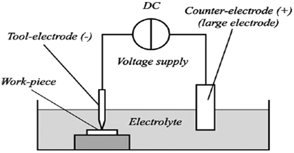
Schematic diagram of ECDM. 57
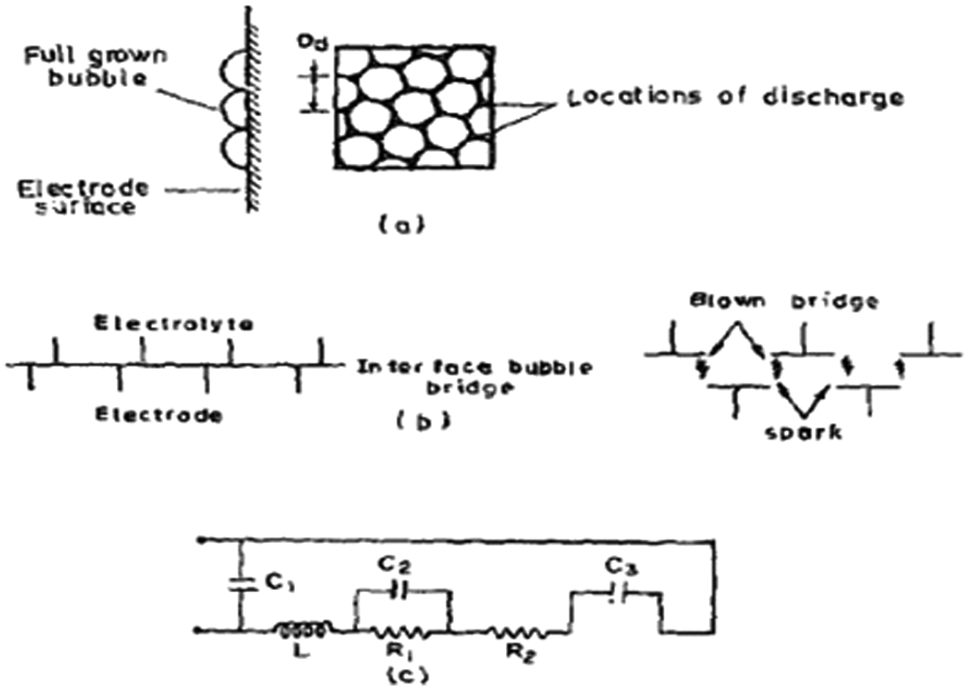
Mechanism of spark generation in ECDM: 58 (a) the discharge location with bubble distribution, (b) the idealized switching-off situation, and (c) the idealized equivalent circuit at discharge.
Process performances in ECDM.
ECDM is quite suitable for the machining of semi-conductive and nonconductive materials such as glass, quartz, and piezoelectric ceramic. It is also a potential candidate for micro-machining. Cao et al. 62 machined microgrooves and 3D structure less than 100 µm, which is shown in Figure 15. This process can be used for dressing/truing of metal-bonded abrasive wheel. 66 A micro-factory refers to a small dimension factory able to produce small dimension products. Wuthrich et al. 67 suggested SACE as a key machining method for micro-factories. SACE is used for manufacturing of channels, as shown in Figure 16, for microreactors. 68 SACE is a promising micro-machining technology for nano-/micro-texturing of micro-devices used in optical, electronics, and biomedical purposes. 69 Traveling wire ECDM can be used to slice the nonconductive materials such as silicon ingot, optical glass, and quartz of meso-size. 70,71
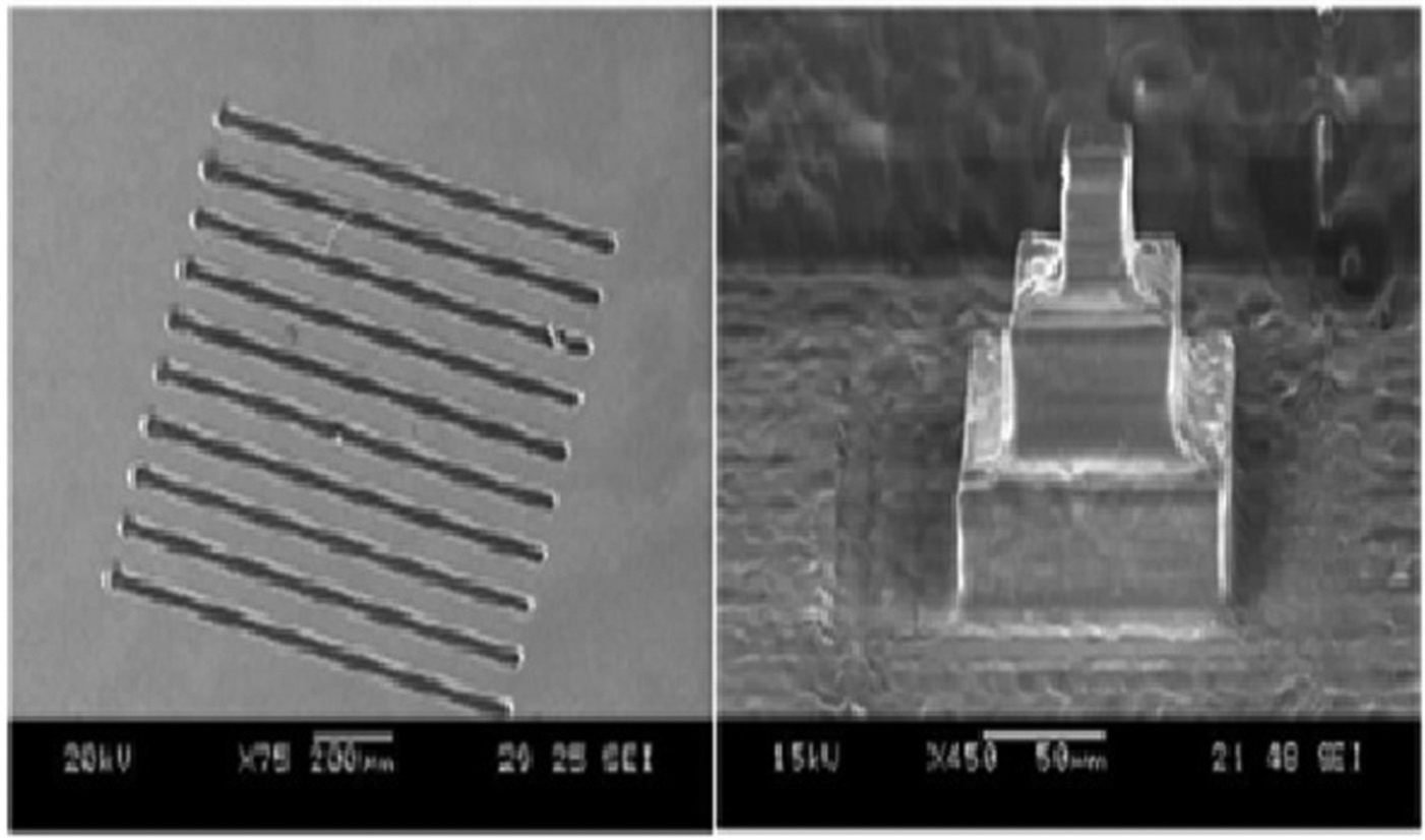
Micro-structures prepared by ECDM. 62
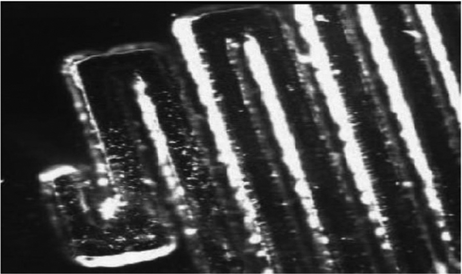
Channels for microreactor application. 68
EDM-based SHMPs
EDM-based SHMPs have been developed by combining EDM, which directly removes the material by thermal action and USM and magnetic field which helps EDM in a positive manner to enhance the process performances. EDM and laser are generally used in a sequential manner to achieve desired profile in the workpiece.
Ultrasonic-assisted EDM
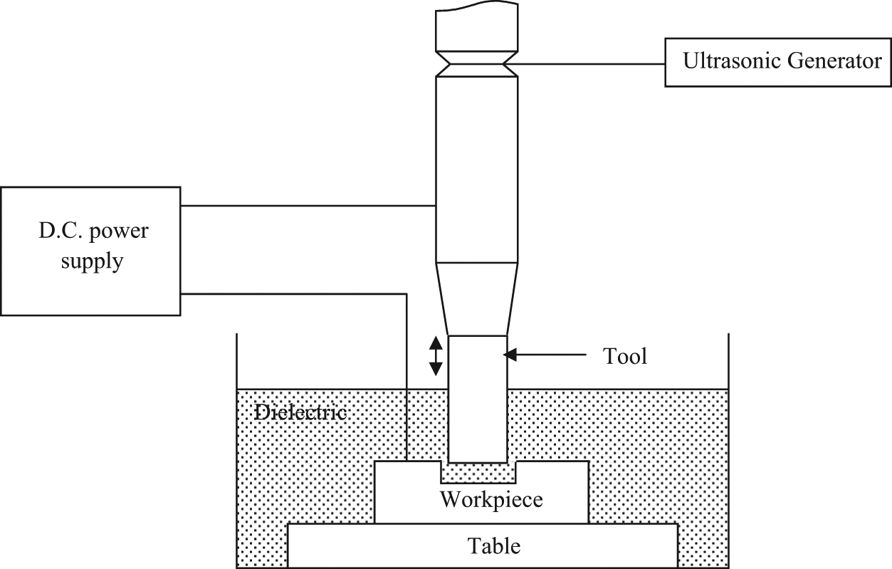
USM has been identified as an UMP that results in low MRR but good surface integrity, whereas comparatively reverse is true to EDM. 1,72 Ultrasonic-assisted EDM (UAEDM) combines EDM and USM. It used to shape advanced materials using thermal energy of the spark generated between anode and cathode, coupled with the ultrasonic vibration of the tool, workpiece, or dielectric. Providing ultrasonic vibration to the tool and workpiece is the most common approach, used by researchers. Figure 17 shows the schematic of UAEDM, where tool has been provided with ultrasonic vibration with the integration of generator, transducer, and horn. Generally, pulsed DC is applied across the gap between the tool electrode and workpiece as that of conventional EDM. However, the constant DC can also be applied in UAEDM. 1
Schematic diagram of UAEDM.
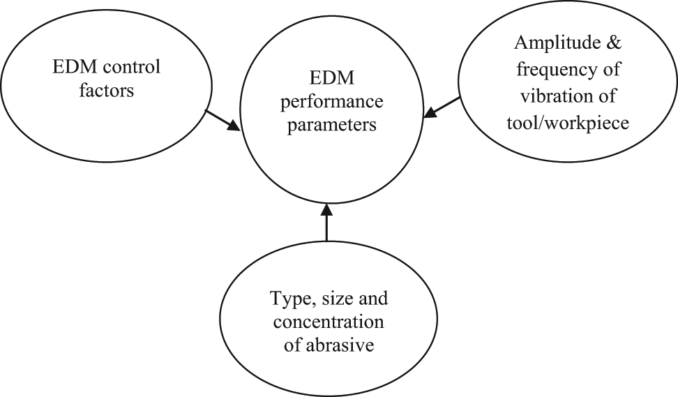
Sometimes, the performance of EDM is hampered by increased debris density, which encourages the abnormal discharge known as arc. The arc results in considerable electrode damage and reduction in MRR. The UAEDM is especially suitable for micro-machining where inadequate flushing may result in frequent adhesion between the tool and the workpiece and subsequently prevents the continuation of the machining, leading to low MRR. 73 The mechanism of material removal in UAEDM is similar to that of pure EDM. The ultrasonic assistance to EDM results in the enhancement of process performances due to improvement in the dielectric circulation and subsequent flushing of the debris. Figure 18 depicts various control factors and process performances in UAEDM.
Process performances in ECDM.
UAEDM is especially suitable for micro-machining of noncircular cross section and drilling of high aspect ratio micro-holes. The micro-gear-array structure machined by UAEDM is shown in Figure 19. 74 Yu et al. 75 drilled micro-holes having an aspect ratio of 29 in stainless steel. Je et al. 76 also drilled micro-holes with diameter and aspect ratio 100 µm and 23, respectively, in steel. Chern and Chaung 77 did mass punching of micro-holes of 200 µm diameter in steel and brass using UAEDM. Huse et al. 78 applied ultrasonic vibration during WEDG to manufacture screw-type micro-tool and step shaft for micro-milling. UAEDM is an ideal method to machine PCD which is otherwise difficult to machine by grinding. 79
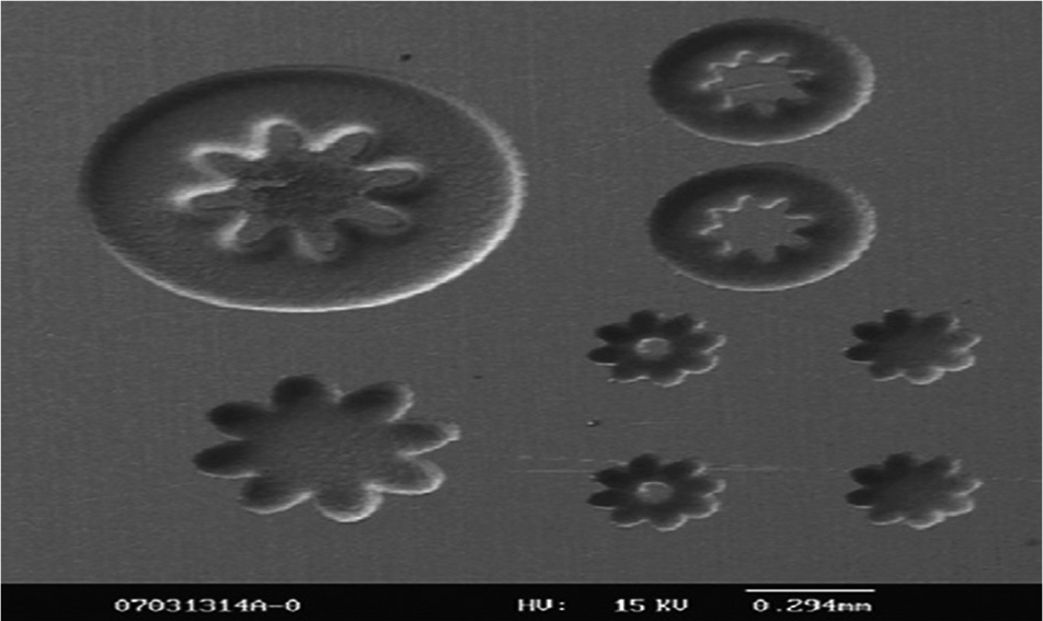
Micro-gear-array machined by UAEDM. 74
Magnetic force–assisted EDM
The efficient expulsion of debris from the machining zone enhances the process performances in terms of MRR, TWR, and surface integrity. The magnetic force–assisted EDM (MFEDM) is a process, where magnets are attached to EDM system, near the machining zone. The setup (Figure 20) consists of a disk, which holds two magnets and is rotated by an electric motor. The strong magnetic force developed by the magnet accelerates the removal of debris from the machining zone, and thus assists in efficient removal of debris. 80,81
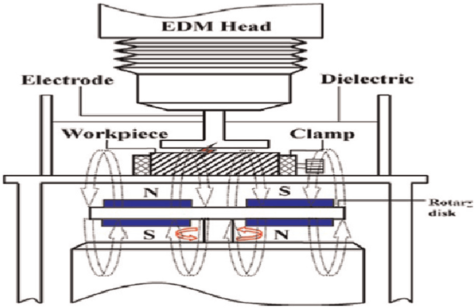
Schematic diagram of MFEDM. 80
Laser-assisted EDM
LBM is an UMP in which a beam of highly coherent laser light is used for machining of workpiece. 82 Laser is well known for its good machining rate and poor accuracy, whereas comparatively EDM is characterized by poor machining rate and good accuracy. The combined process, which is laser-assisted EDM (LAEDM), is used for micro-assembly and for drilling high-quality hole.
Kuo et al. 83 integrated µEDM with neodymium-doped yttrium aluminum garnet (Nd-YAG) laser for precise micro-assembly of pin and plate. The pin was machined to the desired shape with WEDG and the hole on the plate was drilled using the pin electrode with µEDM. Finally, the pin and plate were assembled via laser emission to fuse the assembled pin to the plate. Laser system was also used for the accurate positioning of the parts to be assembled (Figure 21).
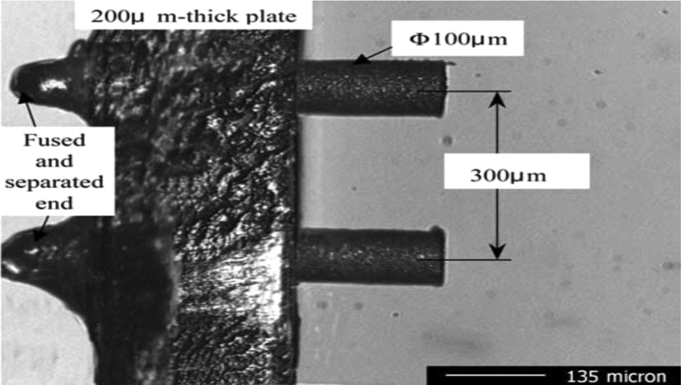
Pin and plate micro-assembly by LAEDM. 83
Li et al. 84 used laser and µEDM to produce high-quality hole in fuel injection nozzles. Initially, the micro-hole was drilled using laser beam and then rimmed out by EDM. Kim et al. 85 also used similar approach to drill micro-hole in stainless steel.
Sequential EDM and ECM HMP
Poor surface integrity like recast layer, residual stress, and micro-cracks are limiting factors for EDM. Thus, it is highly desirable to enhance the surface integrity of the components processed by EDM. The surface generated by ECM is relatively smooth and is free of residual stresses as well as micro-cracks since mechanism of material removal is based on ionic dissolutions. However, ECM is not suitable for micro-machining of metallic parts since the stray corrosion in micro-ECM process results in poor accuracy and unsatisfactory shape of the parts. The researchers have combined EDM and ECM in sequential manner to develop sequential EDM-ECM HMP (SEDCMH), 86 where the bulk shaping is done by EDM and final finishing by ECM. SEDCMH is carried out in the same machine tool with the same electrode but different machining fluids (i.e. EDM dielectric and ECM electrolyte). The schematic of SEDCMH is shown in Figure 22.
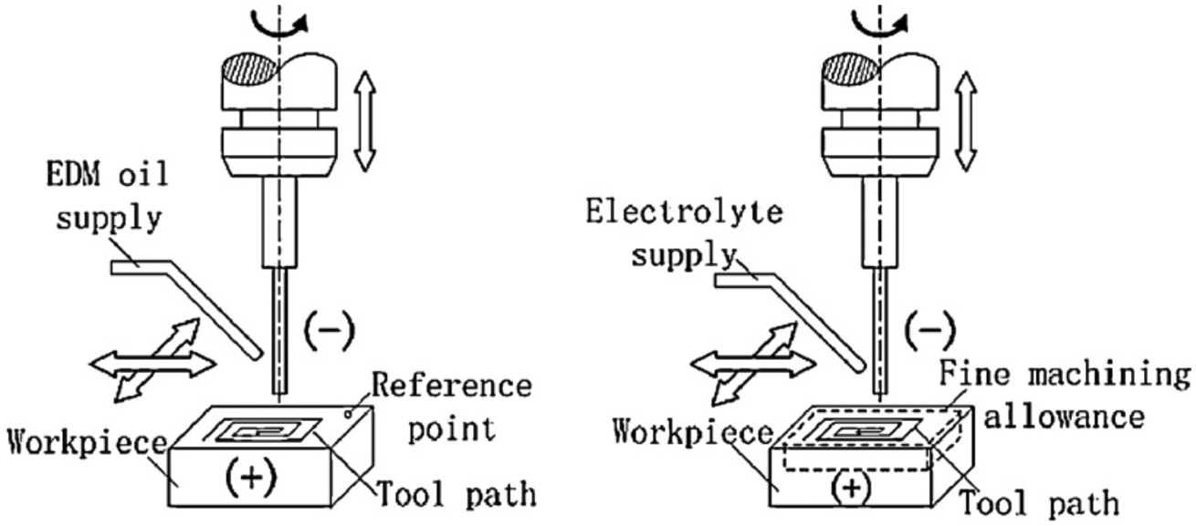
Sequential EDM-ECM hybrid process. 87
The SEDCMH is used to improve the surface integrity as well as accuracy of micro-shapes produced by EDM process.
Remarks
Hybridization of EDM with other machining processes has given new hopes for manufacturing industries to overcome the limitations of EDM and face the challenges posed due to advancement of technology. Difficult to grind materials such as MMCs and superalloys can be machined by combining grinding with EDM with considerable reduction in grinding forces and improvement in the productivity in terms of grinding ratio and surface integrity. Combining EDM with ECM not only overcomes the biggest limitation of EDM or ECM, that is, electrical conductivity requirement, but also increases the MRR by 5–50 times than EDM or ECM alone. Ultrasonic assistance to EDM develops more turbulence and cavitation in the machining zone, and thus promotes better ejection of the molten pool. This leads to less recast layer on the workpiece surface. ECDM and UAEDM are potential candidates for micro-machining of electrically nonconductive and electrically conductive materials, respectively. Not only simple structure such as holes but also complex structures can be machined by ECDM. LAEDM not only overcomes the positioning problem during microfabrication but also helps to achieve high strength assembly. Magnetic force assistance to EDM could reduce the probability of abnormal discharges, and hence enhance the process performances.
Review of EHMPs
Researchers have performed experimental as well as theoretical investigations in order to analyze the effect of input process parameters or control factors on the performance of different EHMPs. Modeling and optimization studies have been carried out to set the process regime for optimal performances. Keeping this in view, the review is divided into two major sections, experimental studies and modeling and optimization studies.
Experimental studies
The aim of the experimental studies is to elucidate the effects of various control factors on the output characteristics such as MRR/TWR, surface quality, thermal and mechanical characteristics, and geometrical aspects. This section presents the comprehensive review of the experimental studies carried out in the EHMPs.
MRR and TWR
Low MRR has always been a limitation for all EDM variants as well as grinding process. Choudhury et al. 88 carried out cutoff EDDG of high-speed steel with varying current, voltage, pulse-on time, and duty factor. It was found that MRR in cutoff EDDG is approximately 5–25 times higher than pure grinding (Figure 23). It was also found that MRR increases with increase in current or pulse-on time and decreases with increase in the voltage or duty factor. Koshy et al. 89 did similar study for cemented carbide and found that MRR in cutoff EDDG is approximately twice than pure grinding. Chandrasekhar et al. 90 elucidated the effect of important electrical parameters and wheel speed on the MRR during cutoff EDDG of high carbon steel and high-speed steel workpieces. They found that MRR was improved by use of rotating wheel as compared to the stationary wheel. Singh et al. 55 performed face EDDG experiments on tungsten carbide–cobalt composite considering wheel speed, peak current, and pulse-on time as process input parameters and MRR and wheel wear rate (WWR) as output parameters. They found that in general MRR and WWR increase with the increase in peak current or pulse-on time. They also found that both the quality characteristics improved with the increase in wheel speed. Wheel speed was identified as most significant factor affecting the process performances in face EDDG. Shu et al. 91 found that the MRR during electric discharge abrasive drilling of mold steel using MMC electrode is three to seven times more than pure EDM.
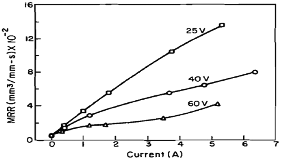
The effect of current on MRR at different voltages during EDDG of high-speed steel (HSS). 88
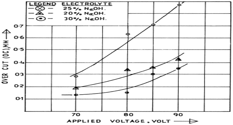
Ghosh 59 and Basak and Ghosh 92 investigated the effect of electrolyte concentration on the MRR during ECDM of glass and found that with increase in electrolyte concentration from 20% to 40%, the MRR of the glass increases by five times (Figure 24). This finding shows that higher electrolyte concentration accelerates the electrochemical reactions between the tool and auxiliary electrode. With the increase in the voltage, the rate of gas bubbles generation increases, which results in a greater amount of spark generation in the machining zone. Singh et al. 93 investigated the feasibility of machining partially electrically conductive material, by using ECSM. They claimed approximately 300% increase in the MRR with increase in the voltage from 20 to 40 V. Liu et al. 94 investigated the effect of peak current and pulse-on time on the MRR during the wire ECDM of Al2O3 particle–reinforced aluminum alloy. They found that for the given range, the MRR increases with the increase in the current. However, they identified that the MRR is maximum at middle level of pulse-on time. Also, by analyzing the voltage waveforms, they concluded that at high level of current and electrolyte concentration, ECDM becomes ECM dominated.
Effect of electrolyte concentration on MRR. 92
Apart from melting and vaporization, chemical etching also contributes significantly to material removal during reverse polarity. Jain and Adhikari 95 compared the ECSM using straight and reverse polarity during machining of quartz and found that ECSM with reverse polarity results in three times increase in MRR than straight polarity. Bhattacharya et al. 63 investigated the effect of different tool tip geometries on the MRR and concluded that MRR is considerably high for taper side wall tool, compared to straight side wall tool. The availability of more electrolyte in the former case resulted in more MRR. Total mass removed from the workpiece and tool has been used as performance criteria by some researchers during ECDM. Jawalkar et al. 96 in their ECDM experiments on soda lime glass found that voltage was the most significant control factor for material removed and tool wear both. Liu et al. 97 developed an innovative process for machining of Al/Al2O3 MMC, where they coupled conventional ECDM with grinding. They claimed considerable improvement of two to four times in MRR due to combined grinding and ECDM action than conventional ECDM.
The depth of the machined hole in a stipulated time has also been used as a criterion to measure the MRR in ECDM. During ECDM, as the tool penetrates the workpiece, the MRR reduces consistently and finally becomes zero. For a particular material and process control factors, the depth up to which the machining takes place is known as the limiting depth. This limiting depth is a major factor that restricts the performance of ECDM. Gautam and Jain 98 tried to overcome this limitation during ECSM of quartz and borosilicate glass, by using an eccentric rotating tool and found that limiting depth increases from 1.0 to 2.5 mm with the increase in eccentricity from 0.11 to 0.95 mm. This condition improves the machining rate by twice. The spherical tool facilitates the better flow of electrolyte by reducing the contact area between the electrode and the workpiece. Yang et al. 99 improved the limiting depth by using spherical tool electrode, instead of conventional cylindrical tool electrode and found that with spherical tool, depth of 500 µm can be achieved with 83% reduction in machining time as compared to cylindrical tool. Jain et al. 100 used abrasive cutting tools to enhance the limiting depth. They also found that MRR and limiting depth increase with the increase in electrolyte temperature. Kim et al. 101 found that TWR increases with the duty factor and is higher for small diameter tool. They claimed that it was due to more current density for smaller diameter tool. During ECDM using aqueous solution, a passive electrolyte layer develops on the workpiece surface that results in lower MRR. Coteaţa et al. 102 developed an innovative setup of ECDM, by using spring to provide the required pressure between the tool electrode and the workpiece. This pressure fractured the passive layer between the electrolyte and the workpiece, and hence increases the MRR.
Shabgard et al. 103,104 and Zhang et al. 105 compared EDM and UAEDM of tungsten carbide and tool steel, respectively, by varying peak current and pulse-on time. They found that MRR in UAEDM was about three to four times more than the conventional EDM. EDM in gas has certain drawbacks such as process instability and low MRR, while ultrasonic assistance has the capability to improve the MRR. 105,106 Imparted ultrasonic vibration to workpiece and MRR was nearly twice in UAEDM. Besides amplitude of vibration, the wall thickness of the pipe electrode has also been identified as one of the important parameter affecting the MRR. Xu et al. 107 claimed that besides melting and evaporation, oxidation, decomposition, and spalling also contribute to material removal during UAEDM in gas. Experimental study 108 of titanium alloy revealed that besides ultrasonic vibration, abrasive size and concentration of abrasive in the dielectric play a significant role in improving the MRR. Improper flushing and frequent adhesion between the tool and workpiece pose machining challenge during µEDM/deep drilling of small hole and result in long machining time. Endoa et al., 73 during drilling of hole of 200 µm diameter with an aspect ratio of 15 in titanium alloy, found that imparting vibration to the tool improved the machining stability of EDM and thus resulted in an extreme reduction in the machining time as compared to EDM. Washheg et al. 109 found similar improvement in machining time during manufacturing of square shaft of 50 µm side and 400 µm length during UAEDM.
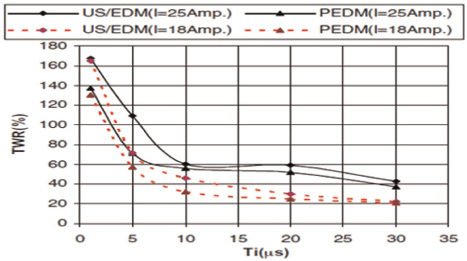
Jahan et al. 110 investigated the feasibility of drilling the micro-holes in tungsten carbide by providing the vibration to the workpiece and found that overall machining performance in terms of MRR, machining time, and TWR improved as compared to pure EDM. Tong et al. 74 performed micro-UAEDM on steel plate with tungsten electrode and found that machining time decreases by 18 times during drilling of blind hole of 180 µm depth at the vibration frequency of 6 kHz and the amplitude of 3 µm. Iwai et al. 111 investigated the feasibility of machining PCD by using UAEDM. They claimed that by providing vibration to the tool and dielectric, the machining efficiency in terms of MRR and TWR increases. Guo et al. 112 imparted high-frequency vibration to the wire electrode and found high cutting rate due to multiple channel and uniform distribution discharge. Experimental investigation 113 showed that ultrasonic vibration to the workpiece enhances the MRR by eight times during µEDM of stainless steel as compared to pure EDM. The ultrasonic vibration of dielectric enhances the kinetic energy of the debris and thus accelerates the debris removal. Some researchers have provided vibration to the dielectric for higher MRR. Prihandana et al. 114 investigated the MRR during micro-UAEDM of copper. While drilling a hole with a depth of 25 µm and an aspect ratio 40, they provided vibration to the dielectric using commercial ultrasonic bath and found that there is approximately 100% increase in MRR as compared to pure EDM. Ichikawa and Natsu. 115 investigated the effect of ultrasonic vibration of machining fluid during micro-UAEDM of tool steel. They claimed considerable reduction in TWR (approximately 55%) due to ultrasonic vibration of fluid than normal EDM. Reduction in short circuits and abnormal discharges were cited as main reasons for improvement in process performance. Abdullah and Shabgard 116 during experimental investigation of cemented tungsten carbide found higher tool wear ratio in ultrasonic EDM (USEDM) as compared to pure EDM (PEDM) (Figure 25).
The effect of pulse-on time on TWR at different currents on WC-Co during EDM/UAEDM. 115
Lin et al. 117 compared the performance of MFEDM and pure EDM during machining of steel and found that MFEDM demonstrated better performance in terms of MRR; however, the TWR was also slightly higher than pure EDM. Heinz et al. 118 applied external magnetic field during EDM of nonmagnetic titanium workpiece in the melt pool. They claimed that application of magnetic field enhances the MRR by 50% without affecting the TWR.
Surface quality
Surface quality is the surface/subsurface condition of a workpiece which includes SR, waviness, surface flaws, and hardness. SR is an important parameter representing the surface quality of any machined part. Singh et al. 55 performed face EDDG experiments on tungsten carbide–cobalt composite by varying wheel speed, peak current, and pulse-on time to study SR. They found that surface roughness increases with the increase in peak current or pulse-on time or wheel speed. Chandrasekhar et al. 90 did similar study with high-speed steel workpiece.
Jain and Adhikari 95 found that average surface roughness during ECSM of quartz increases with the increase in applied voltage. They also found that straight polarity results in more surface roughness than reverse polarity. While performing ECDM on nonconductive materials, the high working voltage may result in poor surface quality in terms of micro-cracks and higher SR. These cracks may lead to total rupture of the component. To overcome this problem, Han et al. 119 proposed the use of micro-textured tool instead of plain tool. The textured tool enhanced the surface quality by improving the surface finish and crack-free surface by enhancement of uniform distribution of discharge spots and reduction in critical voltage.
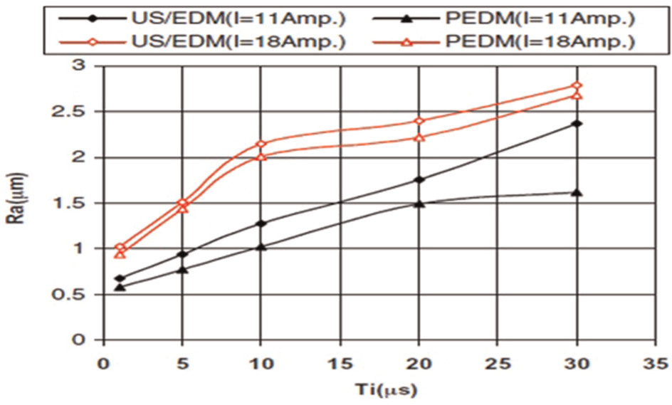
Researchers have found that surface finish is deteriorated in UAEDM. Abdullah and Shabgard 116 compared the SR obtained by EDM and UAEDM during machining of WC-Co composite with varying current, pulse-on time, and pulse-off time and found that the average SR in UAEDM was about 10% more than EDM (Figure 26). Experimental investigations 105,106,108 showed similar finding with regard to SR during comparison of EDM and UAEDM. Kremer et al. 120 and Abdullah et al. 121 studied the surface quality in terms of surface cracks on cemented tungsten carbide by varying pulse-on time and peak current and found that as compared to EDM, the surface quality in UAEDM improves due to decrease in the surface cracks. Figure 27 shows the comparison of surface cracks developed after pure EDM and UAEDM under same working conditions. It is evident that ultrasonic assistance to EDM eliminates surface cracks. Lee et al. 122 found similar improvement in surface quality, by enhancement in the surface finish during ultrasonic-aided wire EDM of Al2O3 ceramic. The polishing action of wire electrode under high-frequency vibration was cited as the main reason for improvement in surface finish. Prihandana et al. 12 investigated the effect of ultrasonic vibration of dielectric and addition of MoS2 micro-powder in dielectric during µEDM and found that quality in terms of black spot free surface improved. Yang et al. 123 proposed new methodology to achieve good surface quality of hole machined by UAEDM. The methodology involved first machining by UAEDM and then polishing the wall of the small hole by ultrasonic vibration with abrasive material. Praneetpongrung et al. 124 tried to improve the surface quality by removing the craters from the surface machined by UAEDM by using ultrasonic vibration and various abrasive suspensions.
The effect of pulse-on time on surface roughness at different currents on WC-Co during EDM/UAEDM. 116
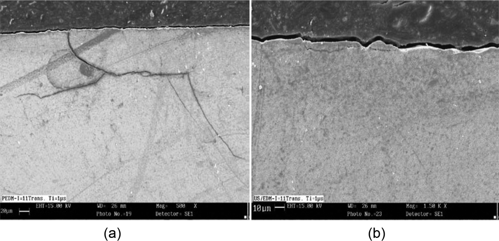
Surface crack on WC-Co after: (a) EDM and (b) UAEDM. 121
Zeng et al. 87 applied SEDCMH during micro-machining of stainless steel using tungsten electrode. Their experimental investigation revealed that combined process results in much better surface finish of 0.143 µm than that obtained by EDM (0.707 µm). They also found that recast layer, burrs, craters, and micro-pores are removed completely by this novel method.
Mechanical and thermal properties
Few researchers have investigated the change in mechanical/thermal properties of the workpiece due to UAEDM and ECDM. Abdullah et al. 121 found that UAEDM reduces the surface hardness of WC-Co composite by 15% as compared to the parent material. Phase transformation and addition of new compound were cited as the main reason for the change in hardness. Guo et al. 125 found that the residual stresses developed during ultrasonic-aided WEDM of high chromium alloy steel are considerably less than that developed by pure WEDM (Figure 28).
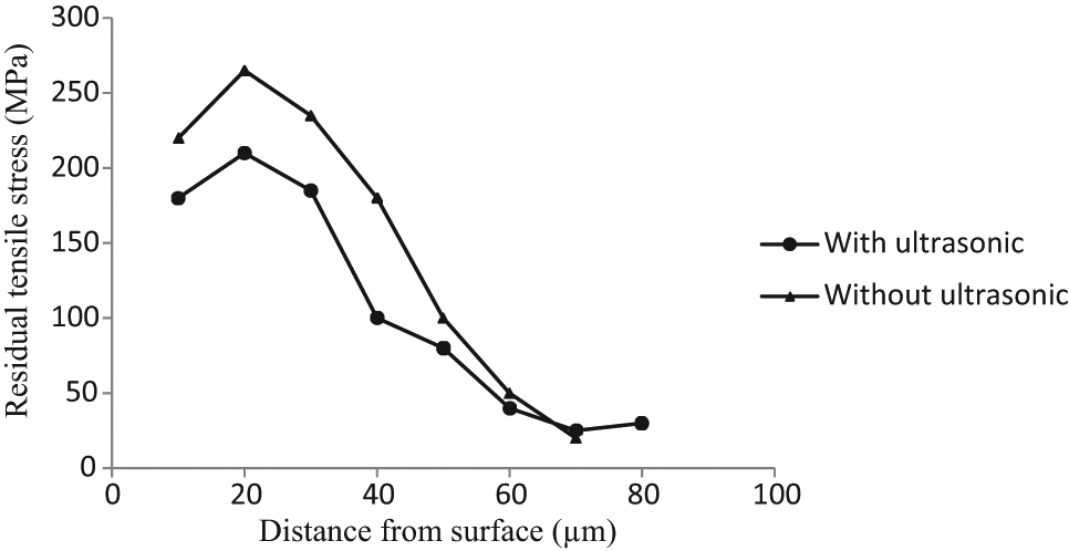
The effect of ultrasonic vibration on residual stress. 125
Kim et al. 101 applied pulsed DC, instead of conventional full-wave DC, to reduce the heat-affected zone during ECDM of Pyrex glass. The experimental investigation showed that the thermal damage of the micro-drilled hole decreases as the voltage frequency increases or duty ratio decreases.
Geometrical aspects
Singh et al. 93 studied the effect of voltage and electrolyte concentration on the diametral overcut during ECSM of piezoelectric ceramic and found that overcut increases with the increase in voltage and electrolyte concentration. Jain et al. 60 and Bhattacharya et al. 63 also observed that overcut increases with the increase in the voltage (Figure 29). They suggested the use of controlled feed for minimizing the arcing, which is the main reason for overcut. Liu et al. 97 observed that eccentric tool with rotation minimizes the taper and circularity error during electrochemical spark drilling of borosilicate glass and quartz; however, quartz demonstrated better performance than borosilicate glass due to higher thermal conductivity. Chak and Rao 126 found similar improvement in radial overcut and circularity error during abrasive mixed ECDM of Al2O3 ceramic. Kim et al. 101 found that hole taper depends on the diameter of the tool electrode and is more for smaller diameter electrode due to high current density. Gravity feed is an easy method to feed the tool electrode during ECDM, but it forms hump at the center while drilling the hole. To solve this problem, Cao et al. 62 used sensitive load cell analogous to servo control of EDM that prevents the direct contact between tool and workpiece, resulting in stable gas film. Furthermore, they compared the KOH and NaOH electrolyte for size and quality of micro-hole and found that KOH with 30% (by weight) gives smallest hole with minimum taper. Laio et al. 127 studied the effect of surfactant addition on the electrolyte during ECDM of quartz. Their experimental investigation showed that by adding sodium dodecyl sulfate surfactant, the current density increases and also it results in stable pulse current. This ultimately resulted in low taper and better quality hole.
Variation of overcut with supply voltage during ECSM of PZT ceramic. 63
Yan et al. 128 combined µEDM and micro-USM to drill a hole of diameter 150 µm with an aspect ratio of 3.5 in borosilicate glass. They found that the combined process is able to produce less than 2 µm difference in the diameter of micro-hole at top and bottom. Furthermore, they investigated that better accuracy is obtained at the middle level of slurry concentration, amplitude of vibration, and rotational speed. Teimouri and Baseri 129 claimed that applying magnetic field during EDM of cold worked steel increases the overcut as compared to pure EDM.
Modeling and optimization studies
To understand the process behavior, it is imperative to model the process parameters. Modeling is a scientific way of simplifying complex process behavior. Depending on the orientation, the models are divided into three groups: empirical model, analytical model, and mechanistic model. Once the model has been developed, it can be optimized for better performances within set constraints. Researchers have applied different techniques for modeling and optimization of EHMPs.
Empirical model
Empirical model is based on the observation and is easy to formulate but applicable for a certain range of process parameters. Empirical model is easy to develop because it does not require deep knowledge of the process and science, and also no assumptions are required to develop these models. It mainly depends on the availability of the representative data and validation. 82 Depending on the complexity of the process, empirical model can be conventional model like response surface model (RSM) or artificial intelligence (AI) model. The representative data for empirical model can be developed by using design of experiment (DOE) techniques such as factorial design (FD), central composite design (CCD), 130 or orthogonal array (OA) based on Taguchi method 131 or by designer’s experience.
FD is a scientific approach to determine the effects of multiple control factors on a response. It may be full FD or partial FD. The full FD facilitates to study the effect of each factor on the response variable as well as the interaction effects between factors. The total number of experiments required in full FD is given by nk, where n represents the total number of control factors and k represents the number of level of each control factors. The only drawback of full FD is very large number of experiments, if the number of control factors or their level increases. CCD is another popular method of DOE which replaces the FD in case of large number of control factors or their levels. The CCD is especially useful in response surface methodology, for developing a second-order (quadratic) model for the response variable. OAs are two-dimensional (2D) arrays of numbers which possess the interesting quality that by choosing any two columns in the array one can receive an even distribution of all the pair-wise combinations of values in the array. OA offers many benefits. There is a large saving in experimental effort and data analysis is easier.
RSM
Response surface methodology is a collection of mathematical and statistical techniques, useful for the modeling and analysis of problems in which a response of interest is influenced by several variables. RSM quantifies the relationship between the controllable input parameters and the obtained responses. 130 In modeling of manufacturing processes using RSM, sufficient data are collected through FD, CCD, or OAs.
Kumar and Choudhury 132 performed cutoff EDDG experiments on the high-speed steel using CCD and developed RSMs for the WWR and SR, considering peak current, duty ratio, wheel speed, and grit size as controllable input parameters. They found that RSMs are able to suitably predict the cutoff EDDG process behavior.
Coteata et al. 133 performed electrochemical discharge drilling of super hard steel by varying tool diameter, voltage, capacitance of the electric circuit, and density of the electrolyte. They developed polynomial model of axial tool wear using full FD and found that voltage and diameter are the most important factors affecting axial tool wear. Jain et al. 100 performed parametric studies on electrochemical spark abrasive drilling using borosilicate glass and alumina workpiece for developing RSMs for material removed and machining depth with input process parameters, supply voltage, and electrolyte temperature. They compared the performance of conventional cutting tool and abrasive cutting tool and found that abrasive cutting tool demonstrated better performance than conventional tool for both the quality characteristics. Sarkar et al. 134 performed electrochemical discharge micro-drilling on the silicon nitride ceramic by considering voltage, electrolyte concentration, and interelectrode gap as control factors. They developed RSM for MRR, overcut, and thickness of heat-affected zone. They found that developed models give good prediction of all the quality characteristics. Also they claimed that voltage is the most significant control factor, affecting all the quality characteristics.
Ghoreishi and Atkinson 135 developed RSM for MRR, TWR, and SR during UAEDM of tool and die steel. The current, amplitude of vibration, and rotational speed of tool electrode were taken as control factors. Analysis of variance revealed that current is the most significant factor affecting the process performances.
Artificial neural network model
Artificial neural network (ANN) is information processing paradigm inspired by biological nervous systems like our brain. In neural network, a large number of highly interconnected processing elements (neurons) are work together. 136 Like people, they learn from experience. In a biological system, learning involves adjustments to the synaptic connections between neurons; the same is true for ANNs. A properly selected ANN is able to train any network irrespective of its nonlinearity and generally; it gives better prediction than other predictive models. 137 Feedforward backpropagation ANN is a boon to the research fraternity due to its simplicity and prediction efficiency. In feedforward backpropagation ANN, the information is forwarded from input nodes to output nodes through hidden layers. There is no backward link, except during training.
Researchers have applied the ANN approach during modeling of EDM process behavior 138 –144 and found better prediction efficiency. Assarzadeh and Ghoreishi 138 developed ANN model for MRR and SR during EDM by using feedforward backpropagation algorithm. The peak current, voltage, and pulse-on time were considered as control factors. They concluded that ANN with 3-6-4-2 architecture is quite suitable to predict the MRR and SR. Tsai and Wang 139 compared six neural network models with different activation functions to predict MRR during EDM. They found that all the ANN models give good prediction of MRR. Tsai and Wang 140 and Markopoulos et al. 141 used ANN technique to predict SR during EDM. Kao and Tarng 142 used feedforward neural network for online monitoring of EDM process. Patowari et al. 143 used ANN approach to model surface modification during EDM with powder-metallurgy sintered electrode. Spedding and Wang 144 developed ANN model for SR, waviness, and cutting speed during WEDM.
Very few researchers have used ANN as modeling tool during EHMPs. RSMs developed for WWR and SR 136 were used to generate training data to develop ANN models for WWR and SR. It was found that ANN with a particular architecture suitably predicts the cutoff EDDG process behavior. Yadav and Yadava 145 developed ANN model for MRR and SR during slotted EDAG of Al/SiC MMC and found that prediction capability of ANN model is within the range of acceptable limit. An efficient pulse classification system is required in ECDM to limit the surface damage and increase the MRR. Mediliyegedara et al. 146 developed an intelligent pulse classification system based on ANN. It was concluded that ANN with SATLINS activation function can be successfully used in the pulse classification of ECDM process. Panda and Yadava 147 developed ANN model for MRR and SR during ECSM of silicon nitride. Supply voltage, pulse-on time, and electrolyte concentration were considered as control factors. It was found that 3-9-2 ANN architecture gives minimum mean square error.
Analytical model
The development of analytical model requires deep knowledge of scientific principles and assumptions, but applicable for very large range of control factors. Analytical model can be grouped into three categories: (1) exact solution based, (2) numerical solution based, and (3) stochastic solution based. 79 The numerical solution–based model can further be divided into finite element analysis (FEA) model, finite difference analysis model, and boundary element analysis model.
Koshy et al. 148 proposed the mechanism of material removal during EDDG of high-speed steel. Considering normal force as a function of workpiece hardness, they also proposed exact solution–based model to evaluate the reduction in normal force due to thermal softening of work material caused by spark. Their experimental investigation on cutoff EDDG of high-speed steel validated the model, as the normal force has been found to decrease due to thermal softening. Yadava et al. 149 investigated the effect of grinding time and feed on the thermal stress distribution during EDDG. Assuming plain strain conditions, they estimated the thermal stresses along the surface using FEA approach. They concluded that thermal stresses are function of grinding time and surface location. In another work, Yadava et al. 150 used same approach to estimate the temperature distribution in the workpiece during cutoff EDDG. Assuming rectangular heat source, they developed code for transient temperature field within workpiece due to grinding and then considered the Gaussian heat distribution to calculate the temperature distribution due to EDM. Finally, they used superposition method to find the temperature distribution due to cutoff EDDG.
Zhang et al. 106 performed UAEDM of AISI tool steel in gas by giving ultrasonic vibration to the workpiece. Based on the assumptions that shape of the crater is spherical, ignition delay is constant and discharge voltage waveforms are same, they developed exact solution–based model for MRR. The developed model was in close agreement with the experimental results. Singh et al. 151 used an FEA approach to develop models for velocity contour and pressure distribution of dielectric during UAEDM. While developing model, they assumed that the flow of dielectric is compressible and 2D. Through this model, they concluded that workpiece vibration is analogs to the reciprocating pump. This pumping action of workpiece accelerates the debris ejection, and thus enhances the process performance.
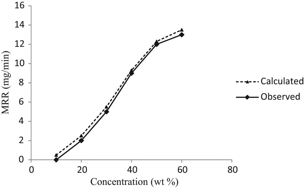
Jain et al. 60 also used an FEA approach to develop model for MRR during ECSM. They hypothesized that heat source is prismatic square in nature, the off time is 0, and ejection efficiency is 100%. The MRR and crater shape were calculated by generating the isotherms for the temperature, equal to and above the softening/melting temperature of the workpiece. They validated their model with the experimental finding of Basak (1992) 60 and found that though the experimental and theoretical values of MRR are different, the pattern of variation of MRR with voltage is the same (Figure 30). Bhondwe et al. 152 also used a similar approach to develop MRR model due to single spark during ECSM. But they hypothesized that heat flux distribution within the spark is as Gaussian. Furthermore, they validated their model using soda lime glass and alumina and found that the MRR predicted by the model is in close agreement with the experimental values.
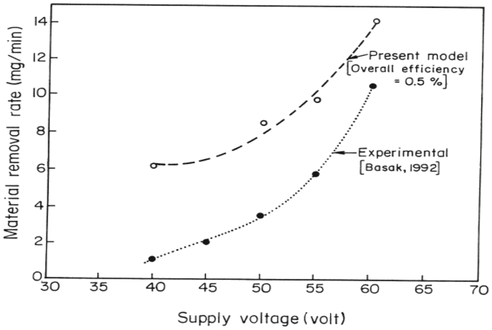
Comparison of model predicted and experimental MRR for soda lime glass. 60
Unstable gas film around the tool electrode is one of the reasons which limit the reproducibility during ECAM. Wuthrich and Hof 153 developed exact solution–based model relating critical voltage and gas film thickness. They demonstrated that adding liquid soap into electrode reduces the dispersion of the micro-hole, and thus results in more reproducible machining. Wuthrich et al. 154 did a similar kind of study during SACE of glass. They concluded that adding surfactant reduces the surface tension and modifies the wettability of the contact surface which results in flattening of the gas bubbles, and thus reduces the gas film thickness and consequently the critical voltage. The performance of ECDM greatly depends on the gap width, so tool positioning control system (TPCS) is of vital importance. Mediliyegedara et al. 155 discussed the design and implementation issue related to TPCS of ECDM process. Due to its simplicity and accuracy, ARX model was used for the designing of TPCS. They found that the stability and the robustness of the controller were higher using sliding average of the peak voltage as compared to the gap sensing parameter.
Mechanistic model
Mechanistic model is developed by combining the virtues of both empirical model and analytical model. The basic model is developed by using scientific principles and certain assumptions, and the various constants, exponents, and so on are determined experimentally.
Basak and Ghosh 58 developed mechanistic model for critical voltage and current assuming uniform heat flux during ECAM. The experimental validation showed that observed values of critical current and critical voltage are in good agreement with the calculated values. Ghosh et al. 156 studied the feasibility of using electrochemical discharge for micro-welding of thermocouples. They developed mechanistic model to obtain the ideal depth of immersion to get satisfactory joint and found that the depth of immersion was mainly the function of wire diameter and material properties.
Optimization
With the advancement of technology, there has been a great demand to develop best quality products at a minimum cost. Hence, the need arises to optimize the process conditions or performances. The complex nature of process behavior has motivated the researchers to develop the optimization techniques that give the best results and are cost-effective. A general optimization problem consists of a single or multiple objectives and is generally associated with a number of constraints and boundary conditions. The steps involved in any optimization problem are explained with the help of block diagram as shown in Figure 31. 157
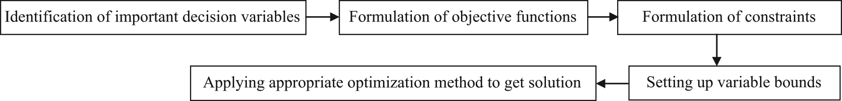
Steps to solve optimization problem.
Many researchers have applied different techniques such as robust parameter design (RPD), simulated annealing, hybrid approach of ANN-genetic algorithm (GA), RSM-GA, and RPD-fuzzy logic for the optimization of process parameters or performances in EDM process. Mahapatra and Patnaik 158 used Taguchi Robust Design Methodology (TRDM) to optimize the WEDM. Using L27 OA DOEs, they found optimum level of peak current, pulse-on time, pulse frequency, wire speed, wire tension, and dielectric flow rate to maximize the MRR and minimize the SR and kerf width. Somashekhar et al. 159 developed an ANN model for MRR during micro-electric discharge machining. Furthermore, they did single objective optimization for MRR using GA. Su et al. 160 used a hybrid approach of ANN and GA for multiobjective optimization of EDM process. Initially, they developed an ANN model for MRR, TWR, and SR and then they did multiobjective optimization by assigning different weights to different quality characteristics. Mandal et al. 161 applied nondominating sorting GA-II during multiobjective optimization of EDM process. MRR and TWR were considered as quality characteristics and pareto-optimal set of 100 solutions were obtained. Arindam 162 used a hybrid approach of RSM and GA during single objective optimization of TWR. Tarng et al. 163 and Yang et al. 164 used a hybrid approach of ANN and simulated annealing during optimization of EDM process. Tzeng and Chen 165 and Lin et al. 166 used a hybrid approach of Taguchi and fuzzy logic for optimizing EDM process.
A very few research works are reported on optimization of EHMPs. Singh et al. 167 applied RPD methodology to optimize the cutoff EDDG process parameters. They predicted optimum level of control factors such as peak current, pulse-on time, duty factor, and wheel speed for higher MRR. They also performed confirmation experiments to verify the predicted results and found that MRR improves at predicted optimum level of control factors. Singh et al. 55 have coupled gray relational analysis (GRA) with RPD in order to predict optimum level of control factors such as peak current, pulse-on time, duty factor, and wheel speed to simultaneously optimize three output characteristics such as MRR, WWR, and SR during face EDDG of WC-Co composite. They registered considerable improvement in multiple quality characteristics at predicted optimum level of control factors. Shrivastava and Dubey 168 used a hybrid approach of ANN-GA to find optimal control factors during EDDG of copper–iron–graphite MMC to maximize the MRR.
Manna and Narang 169 applied RPD method to find optimal control factors during ECSM of fiber glass composite to maximize the MRR and minimize the overcut. Supply voltage, electrolyte concentration, and gap between tool and anode were considered as control factors. They concluded that electrolyte concentration was the most significant factor, affecting both the quality characteristics.
Sundaram et al. 170 used the same method to successfully find optimum control factors during ultrasonic-assisted µEDM of steel to maximize the MRR and minimize the TWR.
Lin et al. 117 have also applied the same approach during MFEDM of steel. They were able to optimize input parameters such as polarity, peak current, pulse-on time, auxiliary current, no-load voltage, and servo reference voltage for maximum MRR and minimum SR. For the same process and similar processing conditions, Lin et al. 171 applied a hybrid approach of RPD and GRA. They found an optimum level of control factors at which multiple quality characteristics such as MRR, TWR, and SR have been improved simultaneously.
Remarks
It can be inferred from the above section that the researchers have contributed significantly to elucidate the effects of various control factors on the different quality characteristics. With few exceptions, generally there is a similar pattern between input and output relation. The researchers have tried to improve different quality characteristics by suitable process/mechanism modifications and have found improvements up to some extent. UAEDM has been found to overcome the limitations of EDM with respect to MRR and surface integrity up to some extent, especially during micro-machining. ECDM has emerged as an efficient process for machining of large class of materials (glass, quartz, and various ceramics). EDAG results in considerable improvement in MRR than pure EDM. Different modeling and optimization techniques have been used by researchers with specific objectives. CCD and OA DOE offer economy of data collection especially during modeling and optimization and thus gaining popularity among research fraternity. Available literature shows that RSM and ANN have been used to model few quality characteristics such as MRR, TWR, and SR. The ANN can be used to model any type of process behavior irrespective of nonlinearity and complexity; however, selecting appropriate ANN structure and representing ANN model in mathematical form is still a challenge. Most of the researchers have used an FEA approach to develop analytical models covering wide arena than empirical models. The simplicity and cost-effectiveness have motivated the researchers to use RPD for optimization of EHMPs; however, the complex process behavior demands the use of more advance optimization techniques.
Future direction of research
The research works carried out in the EHMPs have been discussed in the previous sections. The researchers have contributed significantly, especially for EDM combined with ECM and USM. Theoretically, EDAG has emerged as a process, which significantly reduces the limitations of grinding and EDM, but its cost-effectiveness requires further studies. Also, there is a wide research gap in LAEDM and MFEDM. Ample of research work has been done to study the effects of control factors on quality characteristics such as MRR, TWR, and SR. Considerable improvement in the MRR has been achieved by EHMPs, than EDM. The improvement in MRR is always achieved at the cost of the SR and TWR. More research is required to improve MRR, TWR, and surface finish simultaneously. Also, not much work has been reported on other important performance parameters such as geometrical aspects, thermal effects, and change in the mechanical properties due to EHMPs. EHMPs are thermal energy–based processes, which significantly modify the surface/subsurface structure and mechanical properties such as ultimate strength, bending strength, and shear strength. All the researchers have used diamond abrasive during EDAG. Diamond grit reacts chemically with steel during the machining, and thus results in high WWR. The performance of other abrasives such as cubic boron nitride, silicon carbide, and aluminum oxide during EDAG must be explored. There is a wide research gap in ECDM about the formation of gas film, the change in critical voltage, and the size limitation of the machining processes. To promote the machining speed and its quality simultaneously is still a challenge in ECDM. Also, if the process has to gain wide acceptance in the industry, it is absolutely necessary that reproducible machining is obtained. The reproducibility should be at least few microns for micro-machining applications. UAEDM has a huge potential in terms of machining rate and surface integrity. But to make this process economically viable, the research should be focused on synchronization of EDM and ultrasonic generator and to improve the flexibility of UAEDM. Extensive research work is required for improvement in machine tools, monitoring and control, and development of simulation and computer-aided manufacturing (CAM) software for EHMPs to make these processes industrially popular.
Most of the research works done in the area of EHMPs are on metals and alloys. Very few researchers have considered MMCs and advanced ceramics as the workpiece material. There are a lot many MMCs and advanced ceramics which are widely used in many engineering applications such as cobalt mix with hard tungsten carbide particle, steel reinforced with boron nitride, aluminum boron carbide, and copper–iron–graphite. 172
The modeling and optimization of process variable is a major area of research in any manufacturing process. The literature available shows that in this regard, the minuscule research has been done in the area of EHMPs. Whatever research is available has focused only on few quality characteristics such as MRR, TWR, and SR. Also, most of the researchers have applied only DOE-based modeling and optimization techniques such as RSM and RPD. Rarely have researchers considered soft computing techniques such as ANN, GA, differential evolution, 173 particle swarm optimization, 174 and teacher learning–based optimization 175 for modeling and optimization. Moreover, very few researchers have applied hybrid approach such as ANN-GA, DOE-GA, and ANN-fuzzy logic for the modeling and optimization of EHMPs. This area is still open to be explored.
Conclusion
After comprehensive analysis of published work in the EHMP, the following conclusion can be drawn:
Most of the research works have been carried out in the area of ECDM and UAEDM. Comparatively less work has been reported in EDAG, LAEDM and magnetic force–assisted EDM. Figure 32 shows the percentage distribution of works carried out on different EHMPs as reported in this article.
Hybridization of EDM with other machining processes has the potential to improve the productivity of the process in terms of the manufacturing cast, versatility, and product quality.
EDAG improves the process performance in terms of MRR. The MRR in EDAG has been found to be considerably higher than the conventional EDM or grinding alone.
The effect of EDAG on surface integrity such as microhardness, surface/subsurface cracks, recast layer, and geometrical aspects are yet to be explored.
The UAEDM improves the process performances such as MRR and surface integrity. The MRR in UAEDM has been found to be two to four times higher than the conventional EDM. UAEDM results in better surface integrity by reducing surface and subsurface cracks. UAEDM is quite suitable for micro-machining, especially for producing micro-holes with high aspect ratio.
ECDM has emerged as a process that is quite suitable for micro-machining of electrically nonconductive materials.
The performance of EHMPs mainly depends on the optimum selection of electrical parameters such as peak current, pulse-on and -off time, and voltage and nonelectrical parameters such as rotation and vibration of electrodes, dielectric/electrolyte, and feed rate.
EHMPs, being a complex machining process, may better be analyzed by applying advanced modeling and optimization tools such as AI techniques, in order to understand and optimize the process behavior.
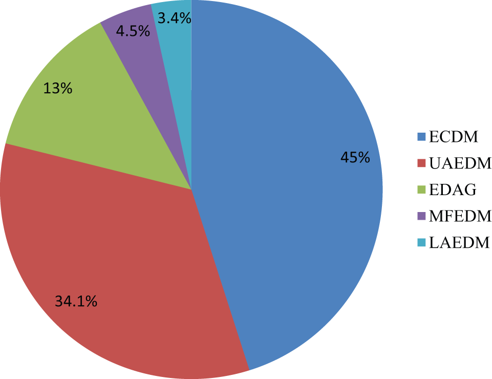
Research work done in EHMPs.
Footnotes
Declaration of conflicting interests
The authors declare that there is no conflict of interest.
Funding
This research received no specific grant from any funding agency in the public, commercial, or not-for-profit sectors.