
Abstract
Electrical discharge machining (EDM) is an exigent focus of interest for researchers since its inception. EDM has a wide range of applications due to its non-contact machining process based on the spark erosion method. EDM is a non-conventional machining process with high potential in the recent industrial era. Due to the few limitations of EDM, many hybrid techniques are evolved in recent years. The present review paper elucidates the in-depth mechanism of the material removal process in EDM. Hybrid EDM processes are also reviewed with special attention on powder mixed electrical discharge machining (PMEDM). A detailed comparison between the EDM and PMEDM is presented with a meticulous portrayal of the advancement and evolution of PMEDM. The emphasis is given on significant performance parameters, namely tool wear rate, material removal rate and surface roughness, besides other parameters. In addition, the study also includes different modelling, optimization, and surface analysis techniques on EDM. The paper concludes with the future scope of PMEDM in the fields of manufacturing along with its applications.
Keywords
Introduction
Electric discharge machining (EDM) falls under the category of non-conventional processes and is based on the phenomena of spark erosion. This technique is widely used in modern times and has been consistently worked since its inception in the late 1940s. 1 Industries like the automobile, electronics, aerospace, and defence along with nuclear power plants, require material of high strength coupled with high-temperature resistance. Machining such materials at a lower cost and high-end quality is a challenge for researchers in the modern age of machining.2,3 The subsequent sections describe in detail the spark erosion phenomena and the working mechanism of EDM.
Spark erosion process
The spark erosion process utilizes a sequence of electrical sparks recurring periodically for the removal of material. The electric spark emanates from the electric potential between the two counterparts, that is, work material and tool inundated in a dielectric medium. The spark erosion is used to cut the hard material with enhanced machining productivity or hard-to-cut shapes and sizes with better accuracy. 4 The sparks generate a temperature close to 8000°C, which produces a plasma channel resulting in partial vaporization of the workpiece. 5 Due to high voltage, the spark initiates at the gap between the two electrodes, causing the dielectric to ionize by overcoming the dielectric breakdown strength. Erosion of material occurs simultaneously from both electrodes. The cumulative effect of successive sparking affects the entire workpiece, causing its erosion. 6 The material is eroded from the tool and the workpiece as minute debris particles after cooling. 7 In EDM, the machining rate is independent of the workpiece hardness since there is no direct contact between the tool and the workpiece, ensuring a higher machining rate. 8 The surface analysis with an optical profiler revealed that a single spark produced during the EDM process was hemispherical or the craters formed were hemispherical. 9 The requirements of high-quality surfaces vary with the field of application. Spark erosion machines, generators and suitable sub-assemblies were further developed for various applications. 10 Chaudhury et al. 11 described a sequence of spark erosion processes in a well-defined manner. The sequence of the spark erosion process is shown in Figure 1.
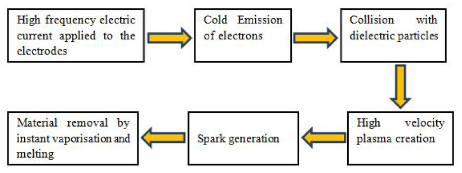
The sequence of spark erosion process (adapted from Chaudhury et al. 11 ).
Essential parameters in electric discharge machining
Electric discharge machining consists of multiple parameters (input parameters or process parameters) affecting the output of the machined workpiece defined by output parameters, also called performance parameters. Process parameters and performance parameters are also known as independent variables and dependent variables, respectively. The Schematic diagram of the electric discharge machining process is elucidated in Figure 2.
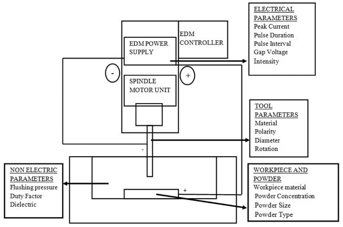
Schematic diagram of the electric discharge machining process.
The process parameters can be subdivided into electric parameters and non-electric process parameters. 12 There are three essential components of the EDM process, that is, workpiece, tool/electrode and the dielectric medium. The material used for machining is called the base material or workpiece. Electrodes can be classified based on the size of the constituent material or its fabrication process. The classification comprises ‘NP electrodes’ and ‘MP electrodes’, fabricated from nano-particles and micro particles, respectively. ‘NMP electrodes’ are the electrodes fabricated by mixing NP and MP in equal weight percentages. 13 The medium wherein the tool and workpiece are submerged is called a dielectric medium. Through literature review, it was observed that experiments were designed using different statistical and mathematical models by varying process parameters like pulse on time, pulse off time, peak current, gap voltage, spark gap, polarity or duty factor.14–21 These process parameters influenced the performance parameter, primarily Material Removal Rate, Tool Wear Rate, Surface Roughness, Overcut and Electrode Wear Rate, to name a few.22–26
Machining mechanism of EDM and its working
EDM is a derivative of spark machining and is characterized by its non-contact machining process. It removes materials by bombarding the workpiece with consecutive, rapid spark discharges from the electric pulse generators and flushes debris with the dielectric fluid flowing between electrode gaps. 27 It is important to note that the spark generation and removal of molten materials are stochastic. The voltage in the gap cannot be sustained at a uniform level. 28 The dielectric medium is used for the discharge phenomena between the inter-electrode gap. Dielectrics are divided into three broad categories, hydrocarbons, gaseous, and water. These dielectrics perform four significant operations in the EDM process, that is, insulation, ionization, removal of debris from the workpiece and cooling of the machined workpiece.1,26,29 The working phenomenon of the EDM process is explained in the form of three phases. 30 During the initial stage, an electric field is generated, which reaches its highest strength in the area where the surfaces of the electrodes are the closest. The second stage consists of the development of a plasma channel in the dielectric medium. The plasma further forms a spark that lasts for microseconds. When the discharge ends, the plasma channel rapidly deionizes. The gas bubbles, however, stay quite long in their position. A detailed schematic of these three stages is presented in Figure 3.
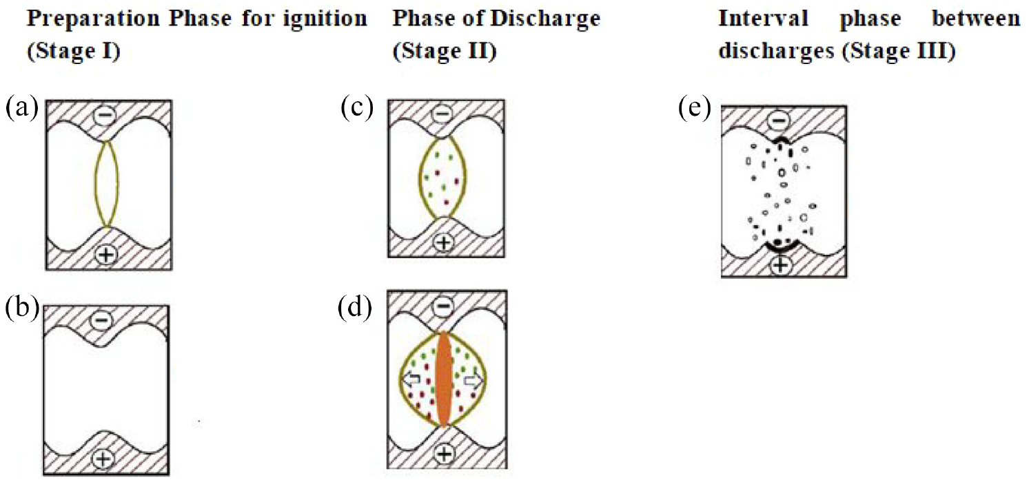
Three stages of EDM process (adapted from Joshi and Joshi 16 ): (a) pre ignition,(b) ignition,(c) plasma,(d) discharge stage and (e) ejection stage.
In EDM, both electrodes (anode and cathode) are immersed in a dielectric medium, which is separated by a small gap of the order from 10 to 100 µm. 29 Further, by applying a voltage of around 200 V between the two electrodes, a controlled spark is generated where the distance between the electrodes is the least. 31 The spark is generated as the voltage applied causes a breakdown in the dielectric medium, causing the voltage to drop by 25–30 V, referred to as discharge voltage and the current. The voltage-time graph (V/s) for different stages of EDM is shown in Figure 4.
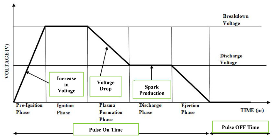
Voltage-time characteristics of EDM Process (adapted from Joshi and Joshi 16 ).
Electrons start flowing between the electrodes, originating from the cathode and travelling to the anode, ionizing the dielectric medium, resulting in the formation of a plasma channel. The process results in intense heat generation in the plasma channel instigating the melting and vaporization of the workpiece. When a spark is generated in the inter-electrode area, there is a subsequent increase in the pressure and temperature, which results in super heating of the material and electrode. The molten material is held in its position due to the high plasma pressure developed initially.32,33 When the turn-on time (spark on time) is over, the spark collapses. To prevent excessive heating, the current is passed intermittently for a small duration (microseconds). 34 After the collapse of the spark, the dielectric fluid rushes back to fill the void so created between the electrodes. The quick and intense movement of the dielectric fluid results in the violent ejection of the molten material. This consequently forms small craters at the location of material removal. EDM process is independent of the workpiece material due to the absence of physical contact between the electrodes. 35
Polarity plays a prominent role as it decides the surface roughness of the machined material. It is observed that positive polarity produced a smoother surface. This was explained by the discharge spot and movement of electrons. When the tool is negative and the workpiece is positive, very small amounts of material migrate from the tool to the workpiece producing a smoother surface. However, when the tool is made anode, the discharge produces more loosely bonded particles that then fall on the surface to produce the rough surface. 13 As the EDM process depends on the flow of electrons and their collision with one another also with the medium; hence the nature of the dielectric medium also plays a significant role in determining the nature of the final machined surface. Experiments conducted by Niamat et al. 36 and Kumar 37 with distilled water and kerosene showed higher MRR for kerosene dielectric than distilled water due to arcing taking place in distilled water. It also showed a lower electrode wear rate (EWR) in the case of kerosene due to the formation of carbon on the electrode. EDM of steel in a hydrocarbon dielectric medium generated a white layer. The white layer formed increases the carbon content more than the base/parent material. The machined workpiece hence showed an increase in resistance to corrosion. The effects of the EDM process were also explored on the non-conductive workpiece and advanced ceramics.38–40 It was further observed that the hydrocarbon oil, when used as dielectric, results in carbon deposition on the tool, which reduced the machining efficiency by lowering the conductivity. Hence, it was concluded that hydrocarbon oil reduces the conductivity, and material removal rate and increases the temperature of the dielectric in micro EDM.41–44
Various forms and configurations of EDM are known to exist. The various forms of EDM were combined with other machining processes to enhancement in their machining capabilities. Various forms of EDM, which differ from each other based on the tool or the dielectric medium, are used for different fabrication processes. Die Sinking EDM as shown in figure 5a, one of the most widely used EDM setups, utilizes dielectric fluid wherein the workpiece is submerged. The dielectric fluid aids in concentrating the spark energy.45,46 In comparison with die-sinking EDM, the next most prominent variation in EDM is the Wire cut EDM as shown in figure 5b. Wire EDM utilizes a thin wire (the most widely used is copper) as a tool electrode. 47 As the need for precision in the micro-manufacturing surface increased, the tool dimension decreased, resulting in the evolution of micro electric discharge machining. Micro EDM (as shown in figure 5c) is employed to manufacture micro holes and micro shafts of size 5 µm. 48
(a) Die sinking EDM, (b) wire cut EDM, (c) micro die sinking EDM, (d) dry EDM and (e) three-phase flow EDM.
Along with conventional hydrocarbon-based dielectrics, various other dielectric mediums were also explored by various researchers. Based on dielectric, the EDM process encapsulates dry electric discharge machining and Three-Phase dielectric flow EDM. In dry EDM as shown in figure 5d, highly pressurized gas travels through a thin-walled pipe, functioning as a tool. The air or gas acts as a coolant between the inter-electrode gap and helps with the removal of debris. It was developed to mitigate the pollution caused by conventional die-sinking EDM. 49 A three-phase flow dielectric medium is where a gas-liquid powder mixture is used as a dielectric medium as shown in figure 5d. The three-phase flow dielectric is produced with the help of an MQL (Minimal Quantity Lubrication) device, which directly supplies the dielectric to the inter-electrode gap through the hole provided in the circular tool. 50
As already stated, dielectric and tools constitute the underlining working mechanism of EDM. Extrapolating this knowledge, yet another machining incorporating the EDM mechanism is EDM Milling and arc machining. A direct modification of EDM, EDM milling works in close conjugation with conventional EDM. EDM milling and arc machining are worked on the principle of spark machining, with an added factor of moving arcs. Wang et al. 51 concluded in an experiment that the rotating graphite tool in EDM milling enhanced the MRR by two-folds in comparison with conventional EDM. Kou and Han 52 showcased that high-speed EDM milling consequently produced higher energy output spark compared to conventional EDM. In recent times, research conducted by Wu et al. 53 elucidated a green approach to the EDM milling method to mitigate the adverse effects of conventional methods on the environment. In the experiment, green pulse power generation was utilized in addition to environment-friendly dielectrics. It was concluded that the approach reduced the adverse thermal effects and enhanced the machining efficiency by utilizing lesser energy. Furthermore, higher machining efficiency coupled with mild electrode wear was achieved. Recent research explored the machining of Titanium and its alloys, including shape memory alloys using EDM and PMEDM. It was concluded that machining with EDM proved to be highly efficient for otherwise hard-to-machine materials like titanium.54,55
Enhancement in machining capabilitiesof conventional EDM
Limitations of EDM
EDM is a process with low machining efficiency and poor surface finish. Zhao et al. mentioned that despite EDM’s potential to produce high complexity shapes, the application is limited, given its substandard machining efficiency and poor surface finish.56,57 The small gap between the electrodes gives rise to a capacitive effect. This effect increases with the electrode area and causes disturbance in the discharge process. The higher peak currents than those predefined on the discharge generator originate due to the capacitive effect and fabricate deeper and more improper craters. 58 As a result of the capacitive effect, higher surface roughness originates due to increased crater diameter, depth, and melted material overflow. 59 Limitations of EDM further include longer lead time and lower productivity. Owing to the complexity of EDM involving spark plasma, flushing conditions, and dielectric medium, researchers are focussing on studying spark and other associated crater formation phenomena to improve the process finishing capability along with its productivity.17,60
Thermally, the EDM process faces another hurdle, as a series of rapid heating and cooling augments the complexity of the physical process. Process parameters like a pulse on time, pulse off time, and the table feed rate must be considered carefully to obtain better results. The surfaces produced using the EDM process result in surface defects. The developed surface defects included voids, dense white layers, serious micro cracks and heat-affected zones.34,43 Recast layer and overcutting further complicate the process. 61 The literature review further showed another problem of EDM, which is not suitable for miniaturized components due to high discharge energy. 62 The electric conductivity of the material constrains the EDM process as its main limitation. Machining material must have electrical conductivity >1 S/m. 63 The low material removal rate coupled with the high tool wear rate and poor surface finish of the machined parts concerns the manufacturers. 24 Fast re-harden and formation of anxieties on the machined surface along with micro cracks bring an eccentric concoction to the machined surface. 64
The limitations of the EDM process have led the researchers to focus on the improved methods. The current research is mainly centred on the combined processes such as Powder Mixed Dielectric (Additive Mixed Dielectric) machining, ultrasonic vibration assisted micro electric discharge machining and dry micro EDM. Modification in tool electrodes, along with other hybrid processes such as cryogenic treatment of tools, is also being studied by researchers.57,65–67
Introduction to hybrid processes and Powder Mixed Electrical Discharge Machining
Hybrid machining processes can be defined as new techniques that combine the physical processing logic of two or more different manufacturing types. Through the review of the hybrid process, it was observed that there was an improvement in overall machining efficiency. This knowledge led to further studies in the field of hybrid processes. 68
The addition of powder in the dielectric medium has also shown improvement in the machining efficiency. Though powder mixed electrical discharge machining is not classified as a hybrid machining process as it does not alter the logic or physical process of machining, it is an improvement to the conventional EDM as it alters the spark discharge and plasma formation in the dielectric. Al-Amin et al. 69 in the review on Powder Mixed EDM (PM-EDM), discussed various factors that affect the machining of EDM. It was concluded that adding powder was the third most influential parameter for a better surface finish after peak current (most effective) and pulse time. Bains et al. 70 experimented on powder mixed magnetic assisted electrical discharge machining using SiC reinforced composite. An increase in MER and a decrease in surface roughness were observed, showcasing an enhancement in performance. Hybrid machining processes, which employ two or more removal methods or machining processes, have also been extensively used for enhanced machining.71–73 Apart from Powder Mixed EDM, Hybrid EDM (H-EDM) and other hybrid machining were employed by various researchers to machined Inconel and titanium alloys.74,75 Zhu et al. 76 illuminated the working of High-Speed vibration assisted electro arc machining. It was observed that in comparison with conventional EDM, VEAM constitutes an additional electromagnetic vibration table and high-pressure pump. The machining efficiency is enhanced by an enlarged discharge gap, low short-circuiting rate, and enhanced polarity effect. It is explained in section 3.1 that the modifications in the discharge gap augment the efficiency of electric discharge machining.
The improvement brought about by the addition of powder and its mechanism is discussed in the following sections. Significant Hybrid processes along with the powder addition technique to improve the machining abilities of EDM are elucidated in Table 1.
Machining principle of hybrid EDM processes.
Meticulous and lucid study of Powder Mixed EDM
To address the aforementioned shortcomings, relatively new techniques were developed to improve the EDM process’s efficiency and surface finish.82,83 The introduction of minute abrasive power (conductive or semi Conductive) into the dielectric gave rise to Powder Mixed EDM (PMEDM).84,85 The incorporation of powder in the dielectric medium considerably affects the performance of the EDM process. The conductive nature of the powder used in the process diminishes the insulating nature of the dielectric and enhances the spark strength.86,87 The MMR and the surface finish are improved due to the stability of the process. Luo and Tripathy and Tripathy experimented with establishing the significance of the PMEDM process. It was found that with the low deionization capacity of pure dielectric and the presence of excessive local debris between the gaps, arc discharge took place regularly. This was overcome by introducing powder into the dielectric, which improved the surface finish, machining rate and surface hardness.84,88,89
A progressive method in the flank of the augmentation of the capabilities of conventional EDM process is Powder Mixed EDM.90,91 Padhee et al. 92 presented the contrast between EDM and PMEDM while using paraffin as a dielectric. It was observed that the MRR was higher for PMEDM as compared to conventional EDM. Analysis of the behaviour of powder particles when introduced in the small gap between the electrodes brought to attention that the added powder particles sometimes acted as a conductor and promoted breakdown in the gap along with higher spark frequency.93,94
Forces acting on the powder particles in the dielectric medium were studied by Talla et al. 95 These different forces acting on the particle are represented in Figure 6.
Forces acting on the powder particle (adapted from Talla et al. 95 ).
Effect of powder properties on EDM machining process
Three significant phenomena, that is enlarged discharging gap, widened discharge passage, and larger and shallower crater formation, result in the machining efficiency improvement due to the introduction of powder in the EDM process. In an enlarged discharging gap, a prolific quantity of current-conducting particles causes electric field aberration in the discharge gap. Compared to the conventional EDM process, the relative evenness and similar insulating property of the dielectric fluid form uniform electric field density, which causes minor initiation abilities of discharge and small discharge gaps. Due to positive and negative charge profusion, a discharge breakdown initiates when the electric field density surpasses the breakdown resistance capability. 96 Thus, the electric discharge can quickly initiate in PMEDM and causes an enlarged discharge gap.
The second phenomenon is widened discharge passage in which the electric discharge carriers in PMEDM accumulate high energy while accelerating towards cathode and anode, simultaneously colliding with the molecules of the dielectric medium. The collision augments their energy and results in the release of more carriers. A cascade increase of carriers in the passage occurs; which results in the widening of the discharge passage. The third phenomenon is the formation of the broader and shallower crater. PMEDM forms an even distribution of large and shallow craters by the dielectric suspended powder, resulting in a better surface finish.
Because of the enlarged discharging gap and widened discharge passage, Intensive discharges are prevented, resulting in uniformly distributed etched cavities. On comparing the surface morphology of the conventional EDM and particle mixed EDM, it was observed that PMEDM produces a machined surface with large and shallow shaved cavities which were evenly distributed. In contrast, conventional EDM produces cavities with uneven and deep holes resulting from intense discharges. Wong et al. 97 first concluded that the introduction of powder increased the gap by a factor of 2 compared to EDM. It was perceived that the effect of added powder in the dielectric was not very significant at lower peak current values.98,99 Uno and Okada 100 and Hosni and Lajis,101,102 through the experiments, confirmed the above-mentioned theory of discharge gap alteration. It was stated that the discharge channel enlarged and widened, which further lowered the breakdown strength of the dielectric fluid. This led to the reduced electrical density at the machining spot, which generated shallow craters.
Reduced insulation strength of the dielectric causes the process to become more static. The bridging effect is the arrangement of conductive powder into a chain-like structure that bridges the tool and the workpiece, which consequently reduces the breakdown strength of the dielectric.103,104 Another significant phenomenon related to powder concentration in the dielectric is electron hijacking which contributes to a rougher surface and reduction in MRR when powder concentration is increased above a certain optimum value. 105 Kumar et al. 106 studied the effect of Graphene nano-powder in PMEDM, the study revealed improvement in surface finish required in the optics and semiconductor industries. In a comparative study between water-based dielectric and hydrocarbon-based dielectric medium, it was observed that SiC particles, in the water-based dielectric, gained high kinetic energy which enabled them to penetrate the workpiece material. This in turn resulted in higher surface irregularity. 107
The conductivity of the added abrasive also contributes significantly to the modification of the plasma channel. It was observed that crater density reduced with the addition of powders with good thermal conductivity. This was due to the addition of thermally conductive powder, the thermal stress on the machined surface decreased. This resulted in a better surface finish. SiC is a well-known compound semiconductor that has been extensively used in Powder Mixed EDM. Research conducted by Kumar et al. 108 explored the effect of Magnetic Field assisted PMEDM with SiC powder. A uniform distribution of spark energy was observed which was attributed to multiple spark generation from a single spark by semi-conductor powder present. It was further noticed that the application of the magnetic field aided in the efficient cleaning of debris from the machining area due to the Lorentz force on the powder present in the medium. Conductivity also influenced the micro hardens of the machined workpiece as illuminated in an experiment. 109 It was observed that with the increase in conductivity, from Chromium to Tungsten, the micro hardness of the machined surface increased. This was due to better sparking and solidified recast layer. Studies conducted on the nature of powder nature further elucidated that conductive and semi-conductive powders formed the aforementioned bridge-like structures which aid in improving the machined surface by dispersing a single current pulse into multiple sparks which results in equal energy dispersion on the machining area.110,111 The addition of semiconductor powder such as SiC diminished abnormal charges (abnormal sparking) which was observed in highly conductive powders such as Aluminium. Tool conductivity also holds a crucial influence on the formation of the plasma channel. It was observed that the conductive tool created a stable plasma channel. 112 Conductive and Semi-conductive powders yielded higher material removal whereas little to no effect on MRR was shown by non-conductive powders. 113 Kavade et al. 114 and Kumar et al. 115 through their experiments elucidated the effects of metal oxide and metal powder on MRR respectively. It was observed that as powder concentration increased, MRR increased up to a certain concentration, above which it remained almost constant. Shallower craters were observed on the surface which was machined with aluminium oxide in comparison with one which was machined with Aluminium.116–118
Trend in powder selection and recent powders
The scope of nano-PMEDM was further studied in the fields of nuclear power plants. The PMEDM also proves to be more efficient than EDM as it eliminates the need for secondary finishing operations.119,120 There has been extensive research conducted on PMEDM 121 for the formation of lubrication layer 122 and many comparative studies between PMEDM and EDM as it is a relatively new technique. 123
Dong et al. in their experiment illuminated that the addition of nano-emulsion improved machining efficiency. This was attributed to the fact, that addition of novel nano-emulsion altered the dielectric properties such as arc breaking mechanism and motion of dielectric between the tool and the workpiece which aided in improving the machining efficiency. It was further concluded that in comparison with water-based dielectric, improved REWR and MRR was obtained in water in oil (W/O) nano-emulsion. 124
A shift in trend from micro powder to nano- powder has been observed. This was attributed to the fact that problem agglomeration of a larger particle near the machining area hindered and exacerbated the machining process. The nano order powder also showcased a better mixing in the dielectric in comparison with larger particles. The addition of nano-powder further enhanced the surface finish as irregular arcing frequency decreased with the appropriate nano-powder concentration. 125
In addition, to shift from micro to nano order powder, a laudable rise in near dry PMEDM has also been observed. The comparative study between air, deionized water, and near dry PMEDM medium conducted by Li et al. 126 elucidated that in comparison with air, near dry PMEDM showed a 1/9th reduction in breakdown voltage which was later explained by the exponential increase in discharge gap. Further studies showed that the addition of graphite nano-powder resulted in a smoother surface in both PMEDM and EDM milling. In comparison with PM- EDM milling, PMEDM showed higher MRR by machining surface movement. 127 The addition of powder in medium and near dry EDM effects was explained with the Impurity breakdown theory. This theory stated that with the increase in powder concentration the breakdown voltage decreased which made the sparking mechanism easier. The powder selection in this experiment showed a novel work. Powders like TiC, TiB, TiB2, B8C, Al3BC and TC4 were used, which have been scarcely used in PMEDM studies. It showed that near dry PMEDM exhibited improved equivalent capacitance stability of the discharge process. Powder shape, in addition to powder size, showed significant influence on the machining performance. Smaller particle size yielded better results in terms of increased MRR which increased with an increase in powder concentration.128,129 But despite enhancement in MRR, a decrease in the surface finish was observed with increased powder concentration. This led researchers to experiment with nano-fibres. Nano-fibres showed better micro chain interlocking which led to a better surface finish in comparison to PMEDM. 112
Evolution of study of Powder Mixed Electrical Discharge Machining
The powder addition saw variation in the machining process since its inception. Various experiments were conducted by altering the process parameters. With the advancement in computational analysis, various modern techniques were also incorporated into the experiment regime. Table 2 presents a detailed study of various experiments in the past 20 years and a detailed discussion of their results. The experimental conclusion of the tabulated data (Table 2) has been discussed in following section 5. For reviewing different aspects of the conducted research, the results are divided into three parts, that is modelling, optimization and surface analysis.
Chronological study of Powder Mixed EDM.
As mentioned before, the above table represents the recent trend in Powder Mixed EDM. Figures 7 and 8 represent frequency distribution for Powder used and Workpiece used respectively.
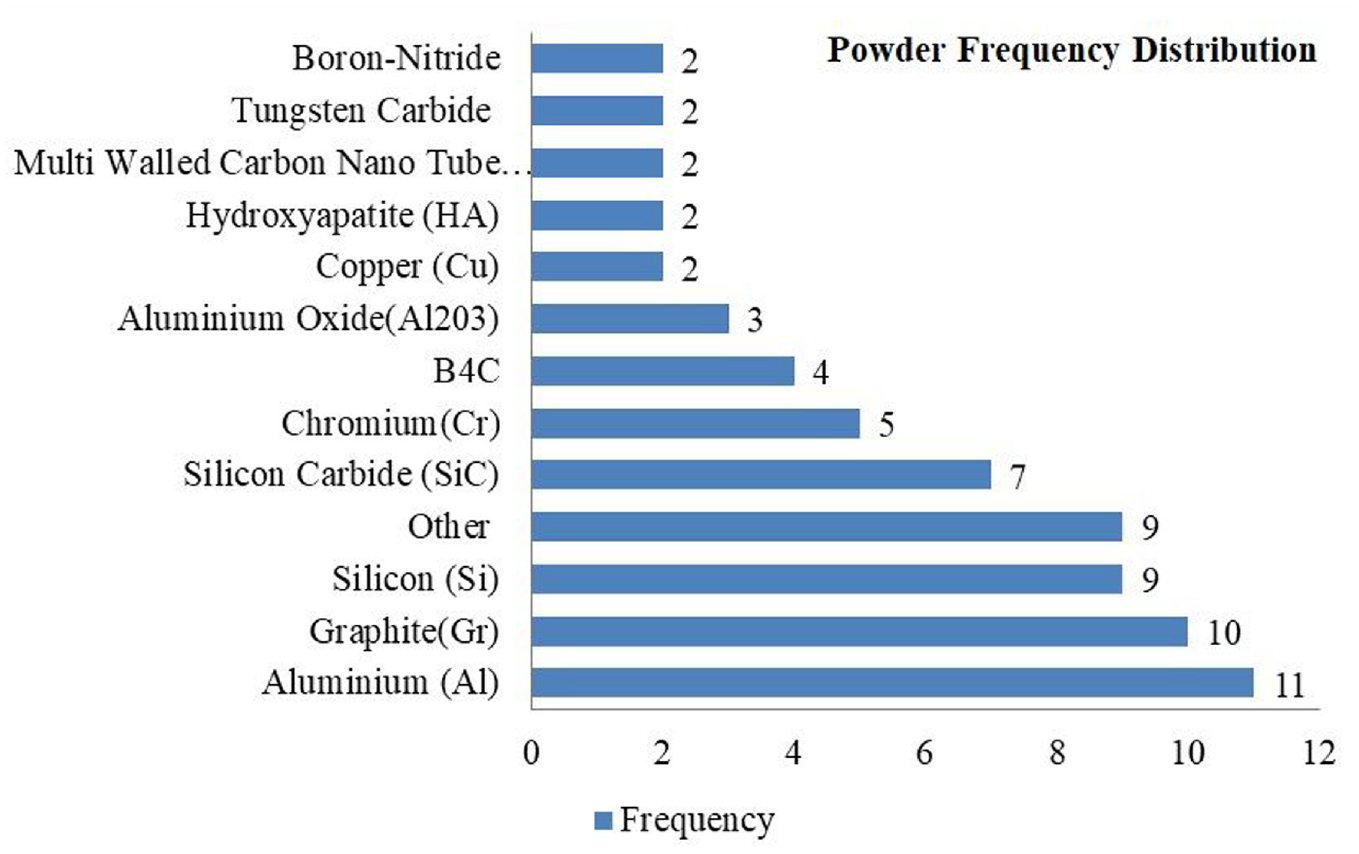
Powder frequency distribution.
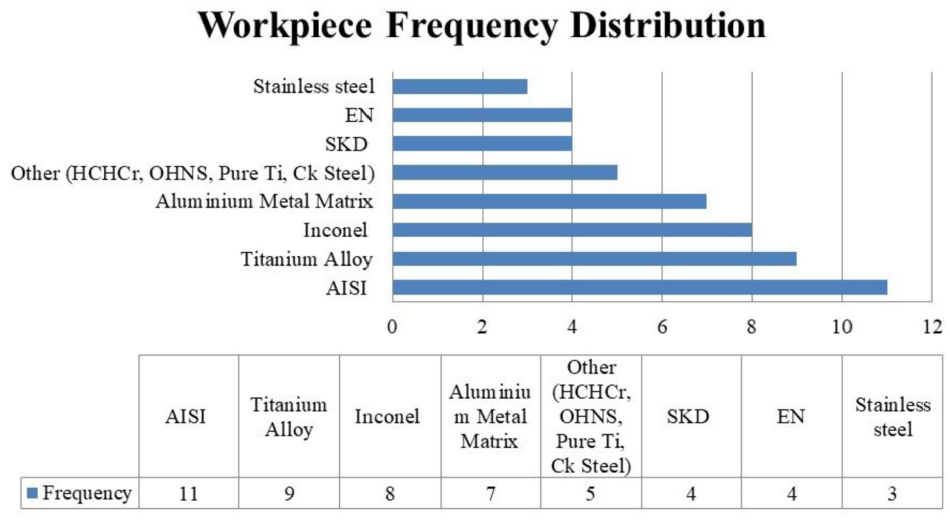
Workpiece material frequency distribution.
It can be observed that Aluminium powder has been used for the maximum amount of time followed by Graphite and Silicon. This was attributed to their Conductor and semiconductor properties. In recent times, a transition towards carbon nanotubes has been observed. This includes both Single walled CNTs and Multi walled CNTs.
It has been observed that AISI has been used the maximum amount of times as workpiece material followed by Titanium Alloy. A recent trend elucidates a transition towards Hybrid Metal Matrix Composites as the base material.
Methods of powder circulation in the dielectric
As it can be observed through the performance and process parameters correlation, powder concentration is attributed to being one of the most influential process parameters. Pertaining to this, the mixing of powder uniformly in the dielectric medium is crucial for an efficient bridging effect. The method of mixing powder depends greatly on its concentration and powder size. Conventional methods of powder mixing include mechanical stirrer. A mechanical Stirrer is a device with a stirrer attached to it. The rotating mechanism usually consists of a motor with varying RPM. Though this method has been employed extensively by various researchers, its shortcomings include jamming and ineffective mixing as the powder size decreases. To overcome this, magnetic stirrers were employed for magnetic powder additives. This employs a rotating magnetic field for stirring. This proved to be more effective in comparison with conventional mechanical stirrers. These methods of uniform mixing of powders include submersion of a rotating stirrer. Though these methods work effectively for micro additives, it has been seen as ineffective for nano additives such as Carbon nanotubes and other nano powders. For a more effective mixing of nano powder, ultrasonicators are employed. This method includes agitating the dielectric medium with an ultrasonic agitator. This method is gaining popularity by its effectiveness and uniformity of powder mixing.
The aforementioned methods include mixing the powder with the dielectric in the tank. Another method of mixing dielectric and powder is by mixing them in a separate tank and then introducing the prepared slurry into the tank. This method is not used extensively as the flow rate effect comes into existence. Furthermore, the probability of pipe jamming and irregular flow rate increases, rendering this method ineffective.
Numerical modelling and optimization of the machining process (tools of analysis)
Attributing to the complexity of the EDM process, it is strenuous to find a correlation between PMEDM process parameters and responses, and pertaining to this various numerical models were employed. 169 Numerical and simulation modelling aids in establishing relationships between input parameters and surface response (Output parameters).170,171 Parametric Optimization is elucidated as the action taken to make the most effective use of the design factors, which in turn ameliorates the efficiency of the machining process. 172 To check the model effectiveness, optimization techniques are employed to map the optimum values of the parameters. Thermo-electrical simulation performed by Tang et al. 173 and Adaptive Neuro-Fuzzy Interference System employed by Hourmand et al. 174 have proven to be extremely useful in modelling and optimizing the PMEDM process respectively.
Statistical modelling techniques
Many mathematical techniques are used to aid the experimentation process. One of the most utilized techniques is Taguchi Orthogonal array. Taguchi’s technique utilizes statistical concepts to enhance the quality of the process as well as optimize the product design. 175 Multiple statistical regression models and Response Surface Methodologies are also well utilized. Multiple linear regression modelling is performed to elucidate the dependence of output parameters on the input parameters 92 whereas, in Response Surface Methodology, independent process parameters are represented in quantitative form. RSM objective does not limit to investigating the response throughout the factor space. However, it extends to navigating the area of interest where the response reaches its optimum or near optimum value. 82 Thermal models are developed by running simulations related to heat. The use of thermal properties like conduction utilized to formulate corresponding equations. 176 Some comparatively new mathematical modelling techniques include dimensional analysis and finite element modelling. 177 Dimensional analysis is a mathematical technique that deals with the physical quantities involved in the experiment and utilizes dimensionally homogenous equations. It forms a model for the performance parameters in terms of control parameters and physical properties of the material. 178 In comparison with Dimensional analysis, Finite elemental analysis (FEA) divides the whole sample into discrete blocks, which are called elements. Loading is distributed based on the governing equations. The solution of the proposed model is derived by the addition of individual elemental solutions. 9
Ming et al. 179 utilized a new thermo-physical model along with FEA to articulate the energy efficiency in addition to environmental effects on Magnetic Field assisted conventional electric discharge machining. Through this experiment, it was successfully concluded that plasma density along with the stability of the discharge channel was improved on the application of a magnetic field with an increase of 29.1% in MRR.
Optimization techniques
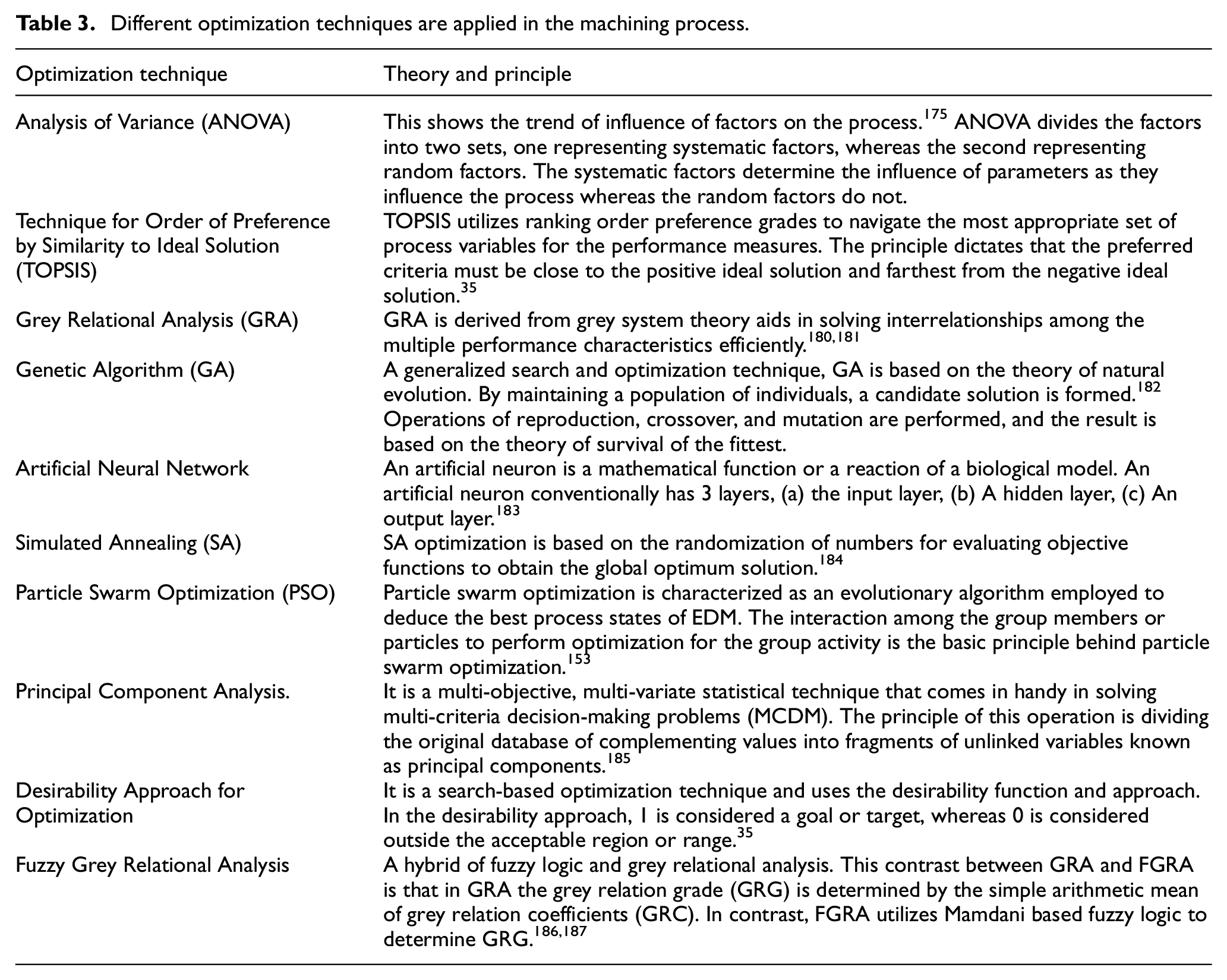
The aforementioned modelling technique describes the path taken by the experimental procedure. By the mathematical models, some optimization techniques are also employed to find the values of the process parameters for which the performance parameter values are optimized. These optimization techniques are mentioned in Table 3.
Different optimization techniques are applied in the machining process.
Recent trends in statistical and optimization techniques employed
A shift in optimization as well as statistical techniques has been observed in recent times. This shift was attributed to a more precise model and prediction with comparatively limited data. Soft computing has observed an exponential rise in manufacturing technologies. This resulted in an augmentation in machining efficiency as well as optimized production cost. An articulate transition can be observed in statistical modelling of the experiment (DOE) with advancements in computer algorithms and mathematical model understanding. The use of non-conventional techniques such as Genetic Expression programming, fuzzy logic, neuro-genetic algorithms, Jaya algorithm coupled with conventional modelling techniques such as Taguchi, and Response surface methodology gained speedy popularity amongst researchers.188–190 Succumbed to the modern requirements of production, deep learning techniques are extensively being used in conjugation with the EDM process. Saeedi et al. employed deep learning as well as low cost optical instruments to examine the surface finish of a wide array of workpiece. The deep learning technique put to use in their experiment was Convolution Neural Network (CNN). CNN based regressor and classifier in conjugation with image processed ROI proved to be highly effective in determining surface defects post EDM process. 191 Ulas et al. 192 examined deep learning algorithms in their experiment with WEDM for optimized surface roughness values. Four deep learning techniques, (i) Support Vector Regression (SVR), (ii) Quantum Support Vector Regression (QSVR), (iii) Extreme Learning Machine (ELM) and (iv) Weight Extreme Learning Machine (W-ELM) were employed to obtain optimized surface roughness values. W-ELM showcased the highest prediction accuracy as well as performance.
Artificial Neural Networks employ different algorithms for modelling experiments. Conde et al. 193 utilized Elman based Layer Recurrent Neural Network coupled with Simulate Annealing to optimize the accuracy of the EDM process. The employed approach proved to be highly accurate in predicting accurate results. El-Bahloul 194 and Sanchez et al. 195 employed deep learning techniques to determine optimum values for MRR, SR and to predict unexpected even during machining respectively. El-Bahloul employed a conjugation of Artificial Neural Network and Fuzzy Logic whereas Sanchez et al. employed Deep Neural Network (DNN) techniques. Through these experiments, it was observed that these deep learning and soft computing techniques augmented the predictive accuracy many folds.
On further reviewing recent trends in EDM modelling and optimization techniques, hybrid techniques, wherein two methods are simultaneously employed were observed. Srikanth et al. 196 employed a hybrid Taguchi-based MOORA method to investigate the effect of input parameters on MRR and TWR. MOORA stands for Multi-Objective Optimization Ratio Analysis which utilizes valuable variables (amplification) and minimization (not useful). This optimization technique was used in conjugation with Taguchi L9 Orthogonal Array and proved to be extremely useful for the optimization of performance parameters. More MCDM (Multi-Criteria Decision Making) methods are being explored by researchers. TGRA (Taguchi Grey Relation Analysis) was employed by Nguyen et al. to enhance the performance of the EDM process. It was concluded through their experiment that a better surface finish was obtained post application of the TGRA method. The confirmation tests confirmed the high level of accuracy between predicted optimum values and experimental values with a standard deviation of 4.1%. 197 A similar technique, the Taguchi based Fuzzy TOPSIS method of optimization was used by Viswanth et al. 198 for machining of AISI 2507 super duplex steel using EDM and eco friendly dielectric. Experiment illuminated the use of L27 Taguchi orthogonal array for modelling and Fuzzy-TOPSIS method for optimization of performance parameters: EWR and MRR. It was concluded that the Fuzzy-TOPSIS effectively performed inter-connection multi-response optimization for different parameters.
In comparison with WEDM, experimentation with new modelling and optimization techniques in PMEDM is still underway, with new optimization techniques being explored. Rouniyar and Shandilya 199 employed Box Behnken Design (BBD) to model their experiment with magnetic field assisted powder mixed EDM. They further used Teaching-Learning Based Optimization technique (TLBO) to optimize material erosion rate (MER). The Teaching Learning Based Optimization technique utilizes growing population based algorithms to obtain a global optimization value by solving linear, non-linear, discrete or continuous data set problems. Das and Chakraborty 200 applied the Grey relation in conjugation with the Preference Ranking Organization Method for Enrichment of Evaluation (PROMETHEE) for optimization of the Green PMEDM process. Through their experiment was concluded that this approach resulted in better response evaluation in comparison with other mathematical models. Incorporation of Adaptive Neuro-Fuzzy Inference System (ANFIS) 201 and juxtaposition of GRA- PCA (Principal component analysis) 202 in PMEDM further paved the way for future research and application of deep learning for optimization and modelling of process and performance parameters.
Significant results elucidated by different research
Parameter modelling employed
Analysis of variance
ANOVA was used to conduct dummy experiments and for the main design of the experiment. It was noted through the experimental values that MRR was dependent on Current, Pulse off time as well as a pulse on time. Maximum material removal was obtained with a copper tool electrode with aluminium powder suspended in the dielectric. HCHcr exhibited the least MRR. 5 Pillai et al. 105 performed F-test and observed that the medium discharge energy regime (D.E.R) had higher MRR than low D.E.R pertaining to better erosion efficiency. It was also observed that the cryogenic treated WC tool produced higher MRR than the conventional tool and also that the tool had a higher tool life in medium D.E.R. The added powder increases the MRR by the maximum value of 574% and the minimum by 165%. Sivaprakasam et al. 161 made use of this technique and concluded that voltage, capacitance and powder concentration and interactions of voltage-capacitance and capacitance-powder concentration had a significant effect on MRR and Kerf width.
Response surface methodology
Kansal et al. 132 conducted 20 experiments and showed an increase in MR with increment in peak current irrespective of pulse duration. It was also observed that MR increased with powder concentration, due to the bridging effect. The experiments presented the best surface finish when the values of input parameters peak current and pulse duration were low. The maximum MR was obtained at 3 g/l Al concentration. Kumar et al. 152 implemented box-Behnken RSM to model their experiment and concluded that peak current, pulse on time, tool material, and powder had a trifling effect on MRR as well as TWR. Dubey and Singh 154 model produced by RSM had 95% agreement with the experimental values. Although, it was observed that current and pulse on time were cardinal parameters for the performance parameter. The confirmatory experiments showed strong confidence, with only an 8.65% deviation. Sahu et al. 162 implemented the Box-Behnken approach of response surface methodology and utilized a lesser number of trials, the experiment was designed. It was concluded that all the input parameters considered were consequential.
Central composite design (CCD)
Face-centred CCD was employed by Kung et al. 4 for the design of the experiment. MRR increased with powder concentration up to maximum value and then further decreased. EWR recorded a different trend, as a decrease with an increase in powder concentration was observed until a minimum value was obtained the post, which is increased. MRR and EWR increased with an increase in both grain size and discharge current. An increase in pulse on time also marked an increase in MRR and EWR. Kansal et al. 82 conducted 30 experiments to study the effect of process parameters on performance parameters. The graph produced by modelling showed an increase in MRR with the increase in silicon powder. A noticeable improvement in surface roughness was concluded when silicon powder was introduced into dielectric. Assarzadeh and Ghoreishi 139 used a face-centred CCD scheme to design the experiment. The model demonstrated that MRR increased with both current and pulse on time. It was observed that high removal rates were obtained at low voltage juxtaposed with a medium level of pulse on time. Discharge current was considered of the utmost importance for surface roughness. Talla et al. 145 employed CCD of response surface methodology to experiment. A total of 32 experiments with varying values of input or process parameters were performed. Improvement in MRR was observed with the addition of powder in the dielectric. Optimized surface roughness (least surface roughness) was observed at 6 g/l concentration. At higher powder concentrations, the surface integrity deteriorated. 149 Al-Khazraji et al. 147 used Box Behnken RSM Modelling. It was concluded that Graphite electrodes gave 82.4% more Heat flux than copper electrodes while using silicon powder. The model developed by Surekha et al. 155 showed that all process parameters influenced the performance parameters except a square of pulse on time. Saharia et al. implemented CCD to form a non-linear regression model. The output or response parameters were MRR and TWR. A total of 27 experiments were conducted. Increase in MRR with peak current was observed in addition to the increase in TWR with the increase in peak current. 157
Taguchi technique
Kumar and Batra 137 applied the Taguchi experimental design to the experiment. Surface characteristics were the main focus of the study. Surface modification was prominently observed with the introduction of powder into the dielectric medium. Peak current was considered to be the most important process parameter. Taguchi’s orthogonal array was employed for the modelling of this experiment. It was observed that there was an improvement in micro hardness in conventional EDM (401.31%) as compared to PMEDM (309.95%). This was due to a change in heat affected zones due to carbon percentage. It was also concluded that micro hardness depended on peak current, polarity and pulse on time. 142 It was observed that TWR along with MRR was influenced by surfactant concentration as well as by discharge current. Whereas discharge current and powder concentration affected RLT and SR. 143 Taguchi L9 orthogonal array was utilized to model their experiment. Through experiments, it was observed that the material removal rate decreased with an increase in the amount of tantalum. Alloys with a higher product of melting point and thermal conductivity required more energy and hence exhibited lower MRR. The study displayed a strong initial decrease in MRR, EWR and surface roughness but recast layer thickness after which they gradually increased. The initial decrease was supported by the fact that HA induced an abnormal discharge and inhibited the transition of energy. 150 Singh 166 devised an experiment where 16 experiments with varying process parameters were performed. It was found that the graphite tool produced minimum MRR and maximum TWR in contrast to the copper tool, which gave maximum MRR and minimum TWR. Wu et al. 130 employed Taguchi L18 orthogonal array for modelling an experiment. Dominant process parameters were Al powder concentration, polarity, peak current, and peak duration. Kansal et al. 133 used Taguchi OA L18 for modelling of machining rate with the signal to noise ratio to be higher the better. Through this, it was concluded that the peak current and concentration of powder were the most important parameters for machining rate, whereas flushing pressure did not have a significant impact on the machining rate. Lamichhane et al. 160 conducted 18 experiments and concluded that the peak current had a significant influence on all performance parameters. Material erosion was directly proportional to peak current. Peak current also increased the surface roughness, which was not desired. This was due to the increase in current intensity. Pulse on time and peak current was the most important process parameters. Jabbaripour et al. 138 used L27 Taguchi OA and concluded an observable increment in peak current, pulse on time, and powder concentration that increase in MRR. Whereas increasing pulse current, surface roughness increased. An increase in powder concentration led to a decrease in surface roughness. When no powder was present in the dielectric, an increase in both TWR and MRR was observed when pulse on time and current was increased. An Increase in powder concentration caused an increase in MRR and a decrease in TWR, which resulted in a better surface finish. 146 Kolli and Kumar 159 selected L27 Taguchi OA due to its uniform distribution of factorial interactions or to minimize the control factors. It was observed that both surfactant concentration and powder concentration played a significant in MRR. MRR increased following the increment in discharge current and pulse on time due to higher discharge energy and the higher number of ions released respectively. It was observed that pulse on time had the most significant effect on surface roughness. Senthilkumar and Muralikannan 165 employed an L27 Orthogonal array to design an experiment and studied the effect of powder addition and process parameters on TWR and MRR. An augmentation in MRR was observed with an increase in pulse on time, whereas a diminishing MRR was observed with enhancement in powder concentration. An increase in pulse on time, and Peak Current led to augmentation in Surface roughness values.
Finite element method
Kansal et al. 136 innovated asymmetric transient thermal analysis using FEM and developed a thermal model to analyse the important thermal processes in PMEDM. The result showcased that the workpiece machined with PMEDM consisted of smaller and shallower craters. The model proved to be in remarkable agreement with the experimental values. Al-Khazraji et al. 147 employed FEM. The lowest values of WLT were 5.0 and 5.57 µm.
Parametric optimization
Analysis of variance
Confirmatory tests with ANOVA showed that peak current and powder concentration are the most significant process parameters. It was observed that higher values of peak current and powder concentration yielded high MRR and smaller SR. 82 Kansal et al. 1 adopted ANOVA for verification of the model and optimization. Optimized values for peak current, powder concentration, pulse on, pulse off time and gain was obtained. The confirmatory tests were in strong agreement with the predicted values, with only a 6% deviation. ANOVA optimization was used by Singh et al. 142 and optimized values were obtained at negative tool polarity and 9 A peak current. The negative polarity of the electrode has more tool wear rate as compared to positive tool polarity. Kolli and Kumar 159 conducted the confirmatory tests using ANOVA. It was observed that for performance parameters, MRR, SR and RLT showed 98.26%, 95.86% and 98.48% confidence in agreement with the experimental values. The final tests showed an error range of just 2.68%−7.70%. Saharia et al. 157 performed confirmatory tests, and optimization utilizing ANOVA. MRR was increased by 122% when the aluminium powder was added and by 82% when graphite powder was added. The increase in tool wear rate was increased by 58% and 37% when aluminium and graphite powders were added respectively. Sahu et al. 162 utilized ANOVA to analyse the trend in the MRR and SR with input parameters. MRR increased with pulse duration up to a certain, and then it decreased. With peak current, MRR followed a similar trend. Surface roughness increased with peak current.
Desirability approach
Optimum values of current, pulse on time, and voltage were calculated using the desirability approach. Smooth surfaces were achieved at lower values of pulse on time and current. Experimentally it was verified that optimum settings had a maximum of 10.71% and 8.41% errors. 139 Kumar et al. 152 implemented Box Behnken RSM to model their experiment and concluded that peak current, pulse on time, tool material and powder had a trifling effect on MRR as well as TWR. Sivaprakasam et al. 161 employed this technique to perform multi-response optimization. The optimization was to maximize MRR and minimize Kerf width and surface roughness. Through confirmation tests, it was found that the values were 100 V, capacitance 0.01 µF, and powder concentration 0.5 g/l were desired.
Grey relation analysis (GRA)
GRA was used for confirmatory tests coupled with ANOVA. A confidence of 95% was obtained. It was concluded that powder concentration, pulse on time, DC, and current were significant parameters, whereas gap voltage was considered an insignificant parameter. 146 Post experiment, GRA was employed by Singh 166 to obtain optimum values. MRR was optimum for a copper tool with a pulsed on-time of 40 µs, discharge current 20 A, and powder concentration of 10%. The optimized MRR value was 18.5436 mm3/min. Similarly, 2.213 microns was the optimum value for surface roughness for the copper tool as opposed to the graphite tool, which produced a rougher surface.
Taguchi optimization
Wu et al. 130 utilized Taguchi optimization by comparing the S/N ratio. Optimized values of different process parameters for surface roughness were concluded to be Aluminium concentration 0.1 g/l, positive polarity, and 0.3 A peak current. Optimization was performed by Kumar and Batra 137 for the given experiment, and the optimum values for the process parameters were obtained. Low discharge current, shorter Ton, negative polarity, and longer Toff were the recommended favourable conditions by the different researchers in their study. L9 OA and Taguchi were used for confirmation of the model and to obtain the optimized value L9 OA for modelling the experiment with three process parameters. The model confirmed that MRR improved with an increase in discharge current and powder concentration. Optimum values for surface roughness were achieved at lower values of discharge current. A similar trend was showcased by recast layer thickness where optimized values were found at lower values of discharge current, powder concentration and surfactant. 143 Ou and Wang 150 utilized signal to noise Ratio (Higher the better) for material removal rate. Pulse duration and discharge current exhibited a similar trend with MRR. With increasing pulse duration, the MRR increased first and then decreased. The decrease in MRR on the increase in more than 100 µs of plasma channel reduced the energy transfer to the workpiece. While increasing the discharge current, the material removal rate increased.
Technique for order of preference by similarity to ideal solution (TOPSIS)
TOPSIS was used to obtain the optimized values of the process parameters. TOPSIS gave an enhanced MRR with decreased SR, EWR and TWR, which resulted in an overall improvement in the performance and surface characteristics. 6 g/l was the optimum value for powder concentration which was obtained by optimization. 146
Particle swarm optimization (PSO)
The results showed that powder enhanced the machining process as pro facto addition of powder decreased surface roughness and augmented MRR. The error percentage of the calculated optimized values was low as compared to experimental values which showed good agreement with one another. 153
Surface characteristics
Through SEM, high-speed framing camera, and energy dispersive spectroscopy analysis, it was observed that Al powder led to the thinnest rim-zone along with the highest material MRR. The discharge energy is dispersed in a larger area on the workpiece. Si produced a grey zone beneath the white zone, which was due to its high heat of fusion property. 10 Tzeng and Lee 43 observed that introduction of powder in the dielectric increased the gap size. The gap size increased with an increase in powder size. Al produced the maximum spark gap, whereas Cu produced the minimum. The influence of powder size was observed on the material removal rate. It was noticed that minute particles increased MRR, and as the powder size increased, there was a decrease in the improvement of MRR.70–80 nm powder size produced the greatest MRR.
Peças and Henriques 59 through experiment concluded that the addition of silicon powder significantly reduced the surface roughness. This was explained based on reduced crater diameter and depth of molten material. Bui et al. 98 showed that the deposition of silver content increases at high concentrations of added powder. The deposition rate of silver decreased with an increase in pulse energy. A decrease in surface roughness was observed.
Through surface analysis, it was observed that there was a decrease in crater size when machined with powder added dielectric than a pure dielectric. The reason for the decrease in the crater size was the alteration in the size and structure of cathode streamers. There was a decrease in crater size by 60% as the cathode streamers formed in PMEDM were long and thin which produced narrow, deep craters whereas the dielectric without the Graphene nano-powder added had thicker branches. 105 Figure 9 represents the cathode streamers in a different medium.
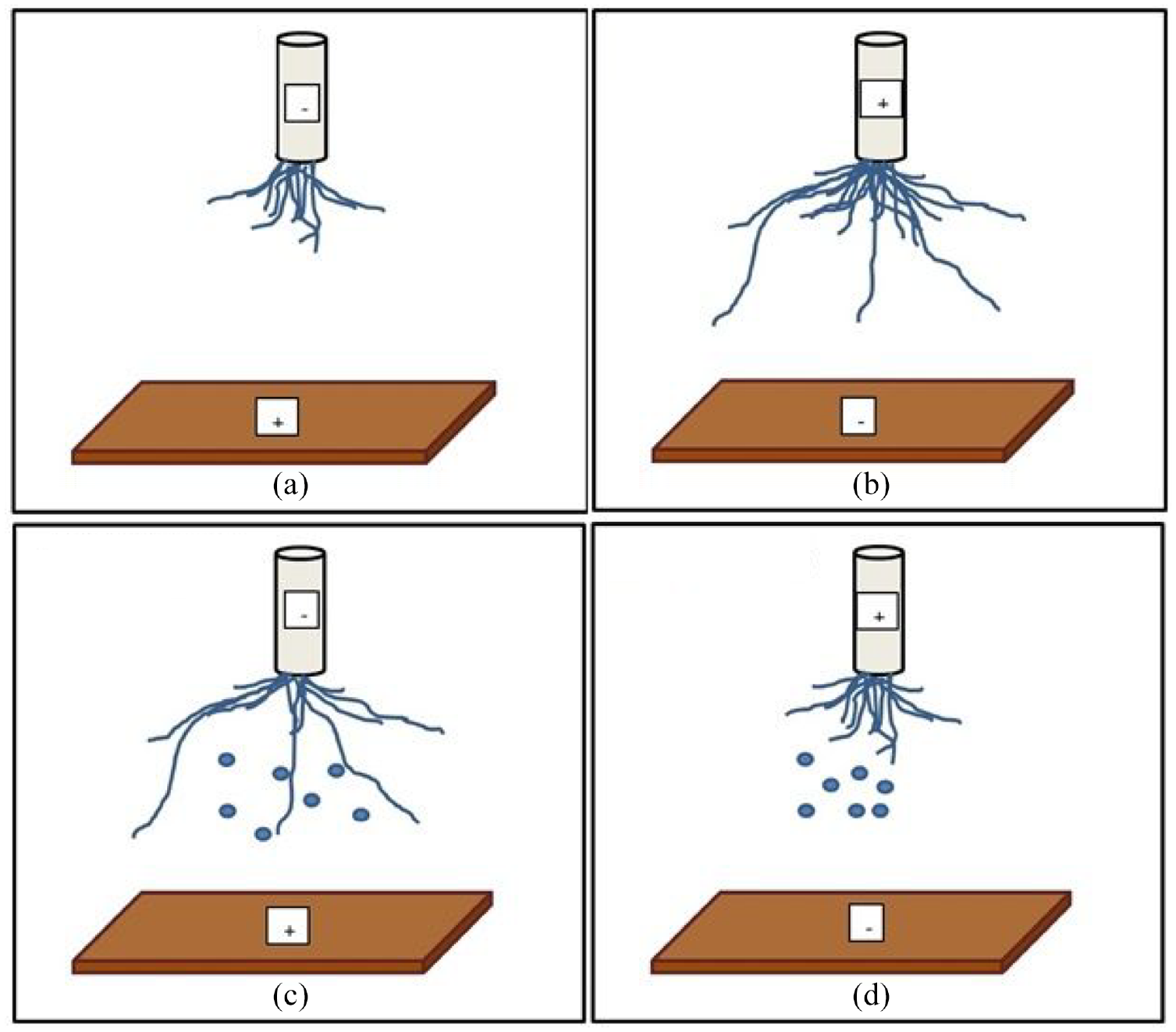
Streamers in different medium: (a) cathodic streamer in pure dielectric, (b) anodic streamer in pure dielectric, (c) cathodic streamer in powder dielectric and (d) anodic streamer in powder dielectric.
Wu et al. 130 deduced through experimental investigation that negative polarity had surface roughness inferior to that of positive workpiece polarity as the negative polarity of workpiece contributed to higher energy distribution which produced shallower craters. Yih-Fong and Fu-Chen 131 investigated RLT and SR. The conclusions drawn from the experiment showed that additives with a particle size of 70–80 µm gave the optimized surface finish. The introduction of powder in EDM improved surface finish and reduced the recast layer thickness whereas aluminium powder proved to produce the best surface finish.
Peças and Henriques revealed that silicon power reduced crater diameter, crater depth and recast layer thickness. Higher concentrations of the powder lead to short-circuiting, which increased the crater depth. The Flushing rate improved the surface roughness for individual electrode areas whereas for higher flow rates; there was no improvement in surface morphology. A 13 regimes experiment demonstrated that the increase in electrode area increased the capacitive effect between the workpiece and the tool. Irregular craters were formed when larger electrodes were used due to irregular discharges. The addition of silicon powder showed a positive influence as it significantly reduced the effect of the electrode area. It was concluded that PMEDM reduced surface roughness, crater diameter, crater depth and white layer thickness. 135 When the powder was added to the dielectric, a 100% increase in micro hardness was observed for all the three working materials. The recast layer appeared to be thicker as the pulse current increased. When the powder was increased, a higher carbon percentage was observed on the surface. Abrasive resistance also increased as the micro hardness increased. 137 Al produced the smoothest surface for all concentrations followed by SiC, Gr, Cr and Fe. Fe powder produced the highest MRR and Al the least. Al was considered to be the best powder. 138
The experiment conducted by Hu et al. 140 led to the conclusion that there was a decrease in roughness by 31.5%, hardness increased by 40%, and wear resistance increased by 100% with the addition of Al particles. The surface was smoother when machined with powder. This was because, in EDM, discharge concentration and the short circuit were observed to be more serious. The discharged pits were broader but shallower and smoother, giving a better surface finish. The Al powder added decreased the insulation strength of the dielectric; as a result, the working fluid broke with more ease. Surface analysis of the machined workpiece showed a significant decline in surface cracks when machined with Ti powder added to the deionized water. It also showed that the recast layer increased with an increase in the current, duration and concentration of Ti powder. Optimized values of process parameters were also deduced. 141
The scanning electron microscope was used by Singh et al. 142 to study the effect of powder mixed EDM. It was observed that surface quality deteriorated at high currents. Self-lubricating properties of the machined surface were observed due to powder getting alloyed with the machined surface and increasing the percentage of carbon. PMEDM produced a smoother surface than EDM. Baseri and Sadeghian 144 employed a rotating tool magnetic assisted PMEDM. Tool rotation aided in improving MRR. This was explained as increased tool rotation improved the debris cleaning from the electrode gap, which further stabilized the process. But higher speeds (>200 RPM) created friction between the tool and the dielectric fluid, which decreased the MRR and EWR increased. The effect of powder concentration was also observed, and it was concluded that by increasing the concentration of powder (up to1 g/l) in the dielectric fluid, the MRR increased considerably as the gap increased. Further increment in powder concentration initiated the Bridging effect, which gave rise to abnormal pulses, which resulted in decreased MRR and Increase TWR. The magnetic field also affected the machining process. Magnetic field improved the MRR by having a positive impact on the process as magnetic field aided in removing or flushing the eroded particles. 144
Talla et al. 145 observed through SEM and XRD that the aluminium powder produced a smoother surface. It was also noted that aluminium powders produced maximum MRR followed by Graphite. This was credited to the lower electrical resistance of aluminium. Process parameters such as Peak current were varied, and it was further concluded that increased values of peak current lead to higher values of discharge currents which caused an increase in MRR. For lower levels of powder concentration, aluminium was recommended for achieving the highest MRR. However, agglomeration of aluminium powder at higher powder concentrations resulted in short-circuiting and arcing. Thereafter, for higher powder concentrations, Graphite powder was deemed appropriate. Surface finish followed the trend that Graphite powder produced a better surface finish as compared to Al and silicon as a result of its small size and abrasive action. A decrease in surface roughness was observed when the powder of Al, Si, and Graphite was added. This was due to the formation of the shallow crater as the plasma channel was modified. Widened plasma channel resulted in better surface roughness.
The surface analysis showed at 4 g/l Si powder concentration; the powder movement performed polishing action, which resulted in a smooth crack-free surface. Powder concentration also significantly affected the recast layer thickness. Formation of Ti Oxide, Nb oxide, Si oxide, Ti carbide was observed at higher powder concentrations. 148 Larger craters were observed with PMEDM which produced a smoother surface. This was due to a decrease in discharge energy density. Due to enlargement in the discharge column, a decrease in surface crack density was also observed. There was a decrease in White layer thickness with an increase in powder concentration. Low-temperature gradient below the surface in PMEDM led to lower micro hardness when compared to conventional EDM. X-Ray Diffraction brought into perspective that due to increased pyrolysis caused by powder mixed EDM, there was the formation of carbides of Ni, Cr and Mo. 95
The micro structural analysis confirmed that the introduction of powder into the dielectric improved the surface quality of the machined surface. A lesser number of cracks and defects were observed in the photomicrographs which were related to the size of the crater formed and the distribution of the recast layer on the surface. 146 Through SEM analysis, it was deduced that surfactant and powder had thermal impacts on the machining as they reduced the abnormal discharge times. The addition of powder resulted in increased MRR and reduced RLT. 159 Ou and Wang 150 utilized SEM (Scanning Electron Microscope) and X-Ray Spectroscopy to study the workpiece after machining. More craters were formed when HA powder was not added to the deionized water. Surface roughness was dependent on input parameters. Surface roughness decreased when dielectric constituted HA powder. The recast layer constituted of titanium, tantalum, oxygen, calcium and phosphorous, which exhibited greater hardness as well as greater anti scratches properties than pure titanium.
Addition of multi-walled CNT aided in the betterment of the machining process and improved machining stability due to a decrease inappropriate sparks associated with low energy pulses and longer pulses on time. The Surface roughness of CNT mixed EDM was lower than the conventional EDM. 151 The SEM micrographs revealed that pulse on time, current and tool material were decisive parameters for the integrity of the machined surface. Formation of debris, deep craters, micro cracks, pockmarks along with residual carbon and copper were also observed on the machined surface. 152
The SEM analysis revealed that the machining produced a better surface finish; this was due to the formation of a thinner recast layer. 154 Surekha et al. 155 showed an increase in surface roughness and hardness with the increase in peak current, pulse on time, gap voltage, and concentration of graphite. The added B4C powder by Wu et al. 156 in their experiment had a polishing influence over microelectrode and microstructure surfaces. This resulted in the smooth removal of processing attachments and turned further helped in stabilizing the machining process. Lamichhane et al. 160 conducted XRD, and SEM analysis showed that the surface which was machined with pure dielectric had a rougher surface as compared to the surface, which was machined with HAp powder added with dielectric. The HAp powder offered a smoother surface and lesser cracks. The formation of inter-metallic compounds was confirmed by XRD analysis.
Saharia et al. 157 showcased an increase in MRR when the peak current was increased. This was since by increasing Peak current, the total available energy for the spark was also increased. Sivaprakasam et al. 161 demonstrated through surface topography that with the use of nano powder added into the dielectric smoother surface was obtained. This was due to the breaking of a single spark into smaller sparks which form a smoother surface. Sahu et al. 162 used FESEM for surface texture analysis. It was observed that recast layer thickness in the case of powder mixed EDM is thinner as compared to conventional EDM. This is explained based on the spark gap and flushing action. Powder added increases the spark gap, which improved the flushing of the debris from the workpiece, reducing the recast layer thickness.
The MRR increased whereas TWR and SR decreased at a low percentage of reinforced particles. This was due to the formation of the protective layer when the percentage of SiC powder was more. This shield protects against sparks. There was a linear relation between pulse current and performance parameters. MRR, SR, TWR increased with pulse current. For higher values of pulse on time, MRR and SR increased, whereas TWR decreased. 163
Jadam et al. 164 studied the effect of peak current on MRR. As the peak current was increased, MRR increased for both conventional EDM and PMEDM as when peak current was increased; higher intensity sparks were generated. PMEDM resulted in better MRR due to the bridging effect. MWCNT mixed EDM seemed to favour the purview of reduced tool wear rate in comparison to conventional EDM. Also, the surface finish of the machined surface appeared relatively more satisfactory after being machined with multi-walled carbon nanotube powder mixed in the dielectric media.
Senthilkumar and Muralikannan 165 utilized SEM and EDS results to analyse the surface characteristics of the machined surface. Development of Micro cracks was observed at high on time and high peak current. Augmentation in the size of Crater and Micro cracks was observed with an increase in the percentage of TiC powder. The use of Si powder in the dielectric resulted in the formation of high-quality surface recast layers which increased with machining time. Different phases like iron-silicon carbide, austenitic and martensitic were observed. SEM analysis revealed the diffusion of chemical elements in the base material. 167
It was observed through this experiment that the addition of powder improved surface roughness and micro hardness for all combinations of current and pulse on time. The concentration of 40 g/l was deemed optimum for preferred surface characteristics. The improvement in surface roughness was about 57.98% along with 129.17% improvement in micro hardness. 168
Significant contributions
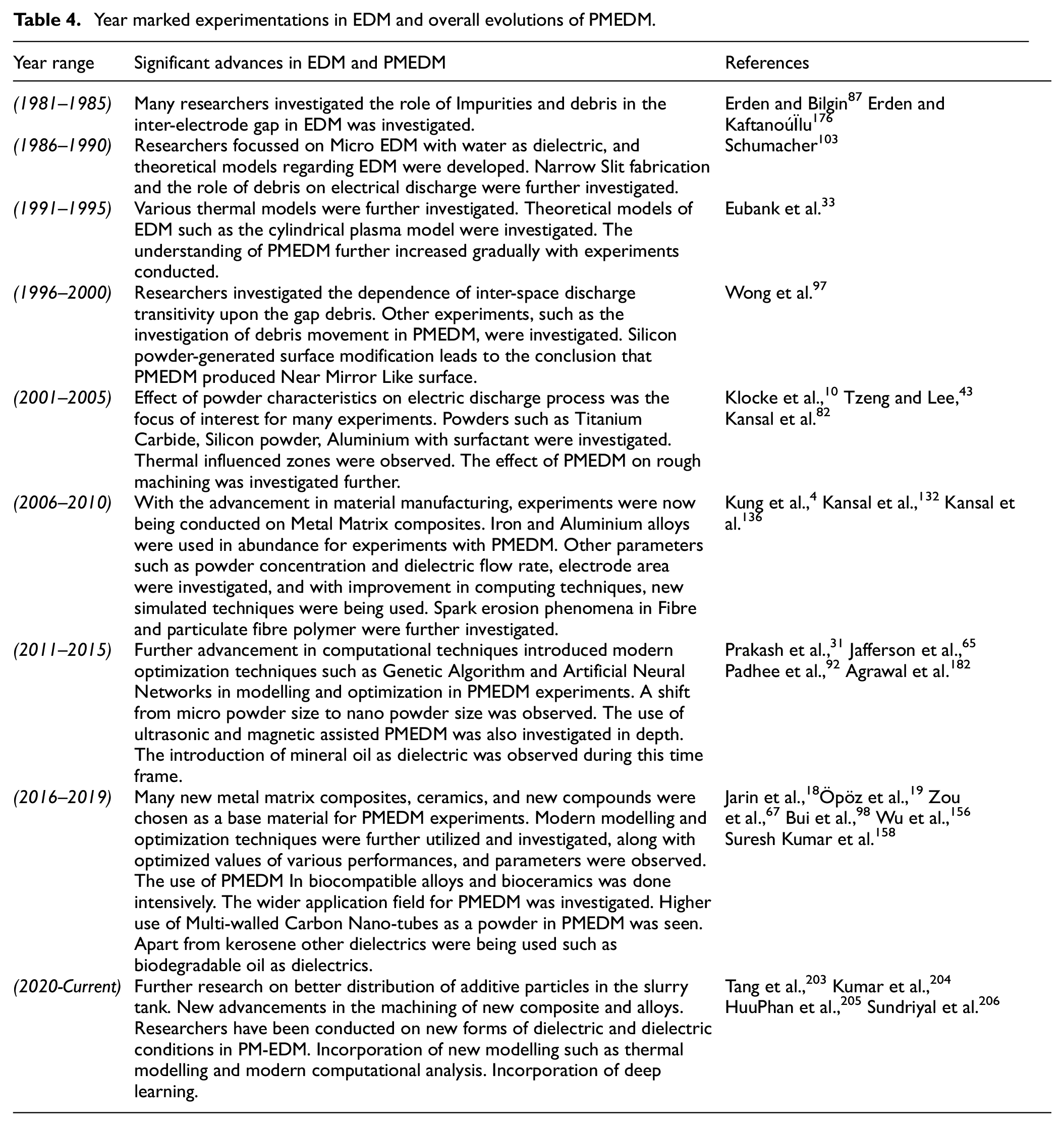
Through this extensive literature review, a chronological evolution has been fabricated which elucidates the evolution in form of milestones. These experiments are illuminated in Table 4.
Year marked experimentations in EDM and overall evolutions of PMEDM.
Conclusion
Significance in the current era
Powder mixed EDM is being used widely in the aerospace, automobile and medical sector. The formation of the recast layer and erosion-resistant layers proves to be useful in these sectors.
Mould and dies are now being fabricated with more precision due to the addition of powder in the dielectric medium.
Due to re-solidification, Powder Mixed EDM is also employed for Powder Mixed Electric discharge coating.
In biomedical applications, it’s widely used to form titanium layers on implants.
A shift in trend from micro machining to nano-machining is supported by new tools used in PMEDM. This articulates that PMEDM has wide applications in the machining of intricate components.
Significant observations
Peak current, powder concentration and turn on time were observed to be the most influential process parameters.
There was a significant decrease in surface roughness with the addition of powder. The introduction of powder into the dielectric significantly increased the material removal rate and decreased the tool wear rate.
The significant phenomena such as the widening of discharge passage, increase in discharge gap, and formation of shallow craters are attributed to better MRR and SR.
Modelling and optimization techniques such as Taguchi, ANOVA and GRA play a significant role in determining the optimum value for process parameters and performance parameters.
During PMEDM, the capacitive effect and Bridging effect significantly influences the process. A balance between the process parameters was observed as one of the biggest hurdles for researchers.
The addition of PMEDM overcame EDM limitations such as poor surface finish, low MRR and high TWR. This proved PMEDM to be a significant hybrid process.
Polarity was a significant process parameter as it determined the movement of the electrons.
Aluminium, Graphite and Silicon were the top three most utilized powders in PMEDM.
AISI, Titanium alloy, and Inconel Alloy were the most frequently used Workpiece materials.
Powder conductivity plays a significant role in altering the discharge plasma in PMEDM. The conductive powder was observed to have an increased machining rate but in addition, caused a subsequent decline in surface quality. This was attributed to the higher bridging effect.
In semiconductor powders such as SiC, an adequate balance was observed between machining rate and surface quality. Non-conductive materials, such as Al2O3 had a trivial or inconsequential effect on the machining performance.
It was observed that nano powder didn’t face an agglomeration problem which was a prominent shortcoming with the utilization of micro powders. Agglomeration hindered the alteration of plasma and caused irregularity in the machining process.
Material applications
New materials are being fabricated with the advancement in technology. Experimentation could be performed with new conductive materials, both as workpieces or additives.
The copper electrode was observed to be the most used tool. With different high conducting materials, different tools could be explored.
A prominent shift towards the utilization of green dielectrics along with green powder can be observed. This shows a new trend where environmental conditions are taken into account while designing the experiment.
Future scopes
New research can be performed on coated tools and their comparative study. Such composite electrodes would advance research. Examples are Aluminium coated with Copper and MWCNT electrodes.
Different researchers performed experiments where EDM was coupled with other machining processes such as ultrasonic assisted EDM. Similar work has not been explored enough with powder mixed EDM.
PMEDM coupled with laser machining and ultrasonic machining is yet to be explored in detail. Not much literature is available in this field.
With the advancement in computational strategies, experiments could be performed by implementing modern methods such as genetic algorithms, ANN, or any combination of modern techniques. Such techniques are already implemented with EDM, whereas these techniques are yet to be explored with PMEDM.
Not enough literature is present for PM EDM of Shape Memory Alloys. This field can be extensively researched.
Little literature is present on Magnetic Field Assisted PMEDM which articulates the relation of varying magnetic field and powder properties.
In comparison with WEDM, more research can be conducted on the application of Deep Learning Algorithms for PMEDM.
Footnotes
Appendix
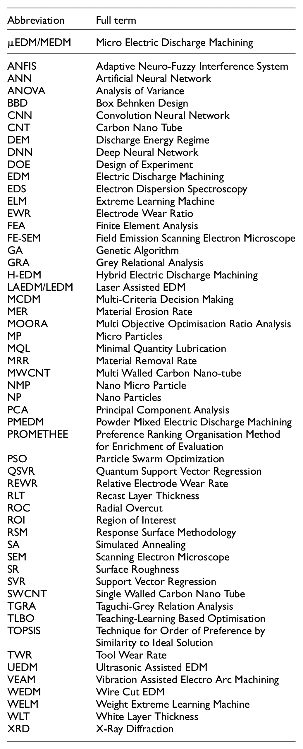
| Abbreviation | Full term |
|---|---|
| µEDM/MEDM | Micro Electric Discharge Machining |
| ANFIS | Adaptive Neuro-Fuzzy Interference System |
| ANN | Artificial Neural Network |
| ANOVA | Analysis of Variance |
| BBD | Box Behnken Design |
| CNN | Convolution Neural Network |
| CNT | Carbon Nano Tube |
| DEM | Discharge Energy Regime |
| DNN | Deep Neural Network |
| DOE | Design of Experiment |
| EDM | Electric Discharge Machining |
| EDS | Electron Dispersion Spectroscopy |
| ELM | Extreme Learning Machine |
| EWR | Electrode Wear Ratio |
| FEA | Finite Element Analysis |
| FE-SEM | Field Emission Scanning Electron Microscope |
| GA | Genetic Algorithm |
| GRA | Grey Relational Analysis |
| H-EDM | Hybrid Electric Discharge Machining |
| LAEDM/LEDM | Laser Assisted EDM |
| MCDM | Multi-Criteria Decision Making |
| MER | Material Erosion Rate |
| MOORA | Multi Objective Optimisation Ratio Analysis |
| MP | Micro Particles |
| MQL | Minimal Quantity Lubrication |
| MRR | Material Removal Rate |
| MWCNT | Multi Walled Carbon Nano-tube |
| NMP | Nano Micro Particle |
| NP | Nano Particles |
| PCA | Principal Component Analysis |
| PMEDM | Powder Mixed Electric Discharge Machining |
| PROMETHEE | Preference Ranking Organisation Method for Enrichment of Evaluation |
| PSO | Particle Swarm Optimization |
| QSVR | Quantum Support Vector Regression |
| REWR | Relative Electrode Wear Rate |
| RLT | Recast Layer Thickness |
| ROC | Radial Overcut |
| ROI | Region of Interest |
| RSM | Response Surface Methodology |
| SA | Simulated Annealing |
| SEM | Scanning Electron Microscope |
| SR | Surface Roughness |
| SVR | Support Vector Regression |
| SWCNT | Single Walled Carbon Nano Tube |
| TGRA | Taguchi-Grey Relation Analysis |
| TLBO | Teaching-Learning Based Optimisation |
| TOPSIS | Technique for Order of Preference by Similarity to Ideal Solution |
| TWR | Tool Wear Rate |
| UEDM | Ultrasonic Assisted EDM |
| VEAM | Vibration Assisted Electro Arc Machining |
| WEDM | Wire Cut EDM |
| WELM | Weight Extreme Learning Machine |
| WLT | White Layer Thickness |
| XRD | X-Ray Diffraction |
Declaration of conflicting interests
The author(s) declared no potential conflicts of interest with respect to the research, authorship, and/or publication of this article.
Funding
The author(s) received no financial support for the research, authorship, and/or publication of this article.