
Abstract
Machining of complex features and holes on superalloys is a topic of both industrial and academic interest. Though the demand for high aspect ratio holes on Ti-6Al-4V is high in aerospace, biomedical and chemical industries, machining the same is very challenging due to the low thermal conductivity and debris accumulation in the machining zone. The present-day methods of hole drilling by unconventional methods like Electric Discharge Machining (EDM) make use of electrodes with poor flushing capabilities. Hence the motivation of the present work is to develop a method to modify the geometry of Electric Discharge Drilling (EDD) tools in order to enhance debris removal. For the first time an attempt has been made to machine micro double-helical grooves on EDD tools in a single pass. Solid, single-helical and double-helical electrodes are developed and through-holes are drilled on a Ti-6Al-4V workpiece. A comparative analysis of the performance of these three types of tools with respect to the machining time, electrode wear rate and hole quality is carried out. From Computational Fluid Dynamics (CFD) simulations it is seen that the double-helical grooved tool is superior in debris removal. The best values of the machining time of 183.33 s, overcut of 2.19 mm, hole taper angle of 7.93° and area of recast layer of 6.66 mm2 are obtained on the holes machined using double-helical electrodes. The mentioned tool has the potential to overcome the problem of debris removal in high aspect ratio hole drilling and surpass the present-day electric discharge drilling tools.
Keywords
Introduction
The improved thermal endurance and mechanical properties like high strength to weight ratio, fatigue endurance and superior resistance against corrosion make Superalloys suitable for many applications in the biomedical and aerospace industry. Ti-6Al-4V is one of the prominent materials among the available superalloys. However, its high toughness and decreased thermal conductivity make it one of the most difficult to machine materials. 1 The ever-increasing demand for miniaturization is prompting the research community to develop methods to drill miniaturized holes with good quality. Micro Electric Discharge Machining (EDM) is a widely accepted and economical way of fabricating micro features, especially micro holes. 2 Of late, much of the research in the field of EDM is focused on developing multi-objective optimization techniques to obtain better Material Removal Rate (MRR) and surface finish. An intelligent and integrated Finite Element Method – Artificial Neural Network – Genetic Algorithm (FEM-ANN-GA) approach to optimize the die-sinking EDM process was developed with a mean prediction error of 7%. 3 The high density thermal electric discharges in EDM cause the formation of recast layers and these thermal stress fields can also be predicted by making use of FEM models. 4 Studies are also driven in the direction of investigation of the relationship between accuracy and depth of micro holes. An analysis of electric discharge drilled micro holes showed that the optimum depth of holes that can be machined using a 200 µm electrode with minimum over cut lies between 2.5 and 5 mm. 5 Using image processing techniques the thickness of the recast layer can be quantified and used to establish a correlation coefficient to map the thickness of recast layer from the data of surface roughness. 6
One of the major challenges in EDM is debris removal. To address this, a system with vacuum assistance and simultaneous flushing through electrode was developed and effective debris removal along with improved surface roughness was demonstrated. Comparative studies with the conventional process showed that vacuum-assisted drilling provided a stable gap voltage and lesser retraction frequency of the electrode. 7 An observation of flushing behavior by particle velocimetry tracking and its confirmation by computational fluid dynamics (CFD) simulation showed that the prime factor affecting the debris trajectory was the outflow of dielectric from the electrode. 8 Modification of the EDM drilling tool is also an upcoming area for enhancing the debris removal from the machining zone with Wire Electric Discharge Turning (WEDT) being one of the prominent manufacturing methods to develop such tools. By making use of a pulse discrimination algorithm in WEDT it was shown that material removal rate is maximum with a low pulse off time, high flushing and low rotational speed. 9 Tools having peripheral micro-slots with an angle of 60° or 75° assists the debris removal from the machining zone and the tool acts as a self-flushing electrode. 10 Deep slotted electrodes improved the MRR during large scale EDM by 91% and during machining of a helispherical feature by 116.7% which validates the efficiency of flushing provided by slotted tools. 11
Out of all the modifications on the tool geometry, the machining of helical grooves on the surface of the tools is the most efficient in enhancing the flushing characteristics and hence has been widely studied. The capabilities of the WEDT process to machine axisymmetric and helical forms on cylindrical workpieces are well established with a maximum percentage dimensional error of 3.10%. 12 Making use of a helical tool for micro-EDM combined with ultrasonic vibration can substantially reduce the EDM gap, variation between the entrance and exit of the hole and the machining time. 13 A novel process for fabrication of micro end mills with low-speed Wire Electric Discharge Machining (WEDM) has been developed and its feasibility for producing micro milling tools with multiple helical cutting edges has been demonstrated. The micro-milled slots machined at a low cutting depth of 2 µm using the developed tool have fewer burrs good surface quality and surface roughness of 1.10 µm. 14
To understand the debris transportation many researchers have modeled the fluid flow of the dielectric in the inter-electrode gap. CFD investigations on flow velocity and stagnation area of debris during WEDM show that the direction of debris movement is in the direction of the jet with the highest velocity and there exists a debris stagnation area irrespective of the flushing method and regardless of the nozzle standoff distance. 15 Another comparative CFD analysis shows that the velocity increases drastically in the radial direction with a high peripheral debris concentration of 611 particles/m2 for a mono holed electrode but for bunched electrodes the velocity field is smooth with a lower debris concentration of three particles/m2. 16
In this work, the process of EDD is selected as it is one of the most economic and feasible ways to machine holes on superalloys and the same being an unconventional machining process produces only insignificant machining forces. Successful drilling of holes in superalloys using EDD depends on an efficient flushing and debris removal system. Debris accumulation in the machining zone leads to short-circuiting, increased secondary discharges in the sides of the holes and dimensional enlargement hence it is crucial to have improved debris removal. From the literature, it can be inferred that helical grooves on the EDD tool can improve the quality of the machined surface and provide better flushing. However, there are very few studies on the effect of the helical geometry on dielectric flushing during electric discharge drilling of holes in Ti-6Al-4V. The purpose of the research is to bring about a better flushing mechanism for improved hole quality and debris removal. Hence in the present work, the authors have developed a novel method to machine micro double-helical grooves on EDD tools in a single pass. A comparative study of the holes drilled by using solid, single-helical and double-helical tools is carried out and the effect of different tool geometries on the debris particle accumulation is modeled using CFD.
Development of the double helix machining process
As the existing methods for machining double-helical grooves on soft materials in the meso and microscale are complex and expensive, the authors have developed a novel machining strategy for the same.
Concept of the double helix machining process
The double helix machining is achieved by adding modifications to the WEDT process. To perform double helix machining by WEDT the authors have designed a wire guide system to machine two helical grooves in a single pass. It eliminates the complexities involved in repositioning the workpiece to machine the second groove when machining is carried out in two passes. The mentioned wire guide system consists of two wire guides to position the moving wire; a fixed one and a movable one. The distance between the wire guide discs can be changed by using a micrometer attached to the movable wire guide. If the distance between the two wires is kept equal to the pitch distance of the helix to be machined, the two helical grooves start at diametrically opposite positions. To generate double-helical grooves at a particular helix angle, the pitch can be calculated as
Where, p is the pitch of the helix in mm, d is the diameter of the workpiece in mm, α is the helix angle in degrees.
If N is the rotational speed then the table feed can be calculated as

In the present work three types of electrodes are machined for performing EDD; solid, single-helical and double-helical. The schematic representation of the machining of these three types of electrodes is shown in Figure 1. The solid electrode is machined by turning a 6 mm copper rod to 1.5 mm as shown in Figure 1(a). For the second type of electrode, after the rod is turned to 1.5 mm the micro single-helical groove is machined by WEDT with a low rotational speed of 3 rpm as shown in Figure 1(b). The third type of electrode with the micro double-helical grooves are machined by using the developed novel wire guide system. Once machining is initiated and half a rotation is completed machining of the second helical groove begins as shown in Figure 1(c). As the machining progresses both the grooves are machined simultaneously.
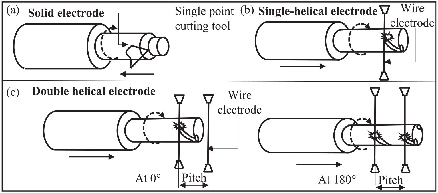
Schematic representation of the concept of machining of: (a) solid, (b) single-helical, and (c) double-helical electrodes.
Fabrication of the wire guides
Two aluminum discs of 100 mm diameter with a circumferential V groove of depth 6 mm comprised the primary structure as shown in Figure 2(a). The v grooves hold the moving wire in position. A V-shaped opening is provided on the disc at the sparking location. One of the discs is fixed and the other is movable.
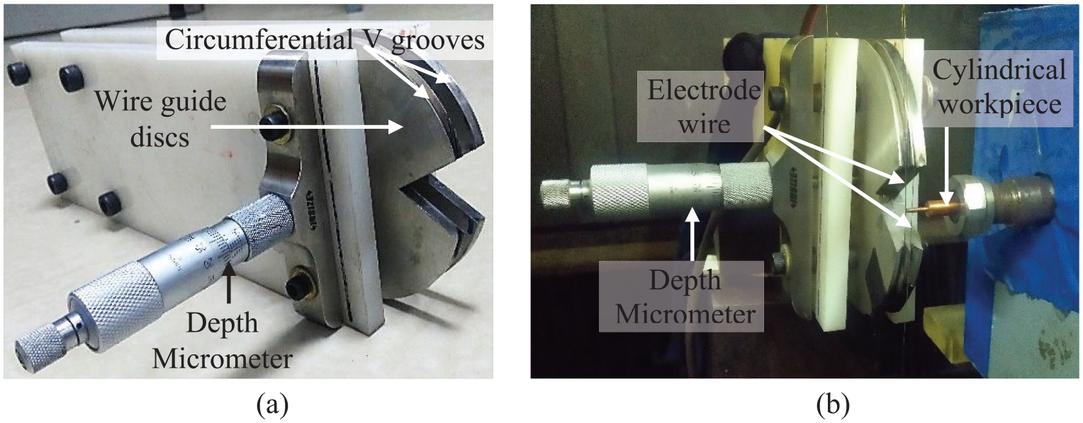
(a) The novel wire guide and (b) the novel wire guide set on the machine table.
A depth micrometer as seen in Figure 2(a) and (b) was press-fit to the movable wire guide using a roller bearing and insulating bush. Precise forward and backward motion is facilitated by the depth micrometer to change the distance between the wire guide discs and thereby the distance between two wires. In Figure 2(b) the electrode wire can be seen passing through both of the wire guide discs.
CFD model for flushing the debris
Formulation of the model
In order to find the helix angles on the EDD electrodes that allow maximum debris removal; the debris transportation from the machining zone and the volume fraction of the debris at various time steps were computed using CFD models in ANSYS Fluent. The current model is based upon rigorous 3-D multiphase flows. The Lagrangean-Lagrangean model was selected to model the flow as the model provides accurate results for multiphase flows. In order to account for the rotation of the solid electrode a fully three dimensional swirling flow was considered and the moving mesh method was selected for the solid electrode domain. The continuity equations and the momentum transport equations are solved for both phases.
The mass conservation equation for one phase q:
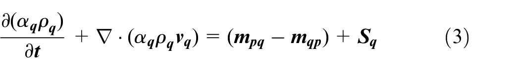
The momentum conservation equation for one phase q:
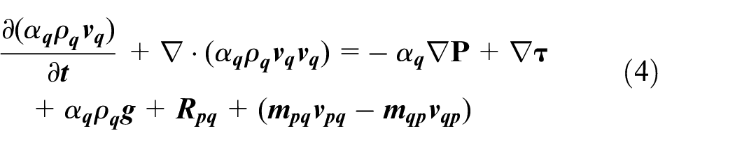
Where
The drag function f′ is introduced by the default model of Schiller and Naumann
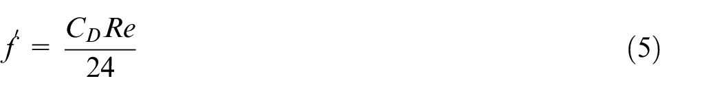
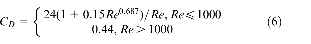
Where
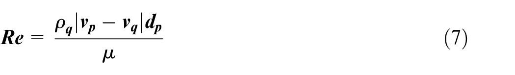
The relative Reynolds number for the primary phase q and secondary phase p is obtained from
The Schematic diagram of the flow region showing the boundary conditions and the solid and fluid cell regions can be seen in Figure 3. A no slip wall is considered as the lateral outer enclosure of the flow domain, a pressure outlet condition with atmospheric pressure and a velocity inlet condition with a very small velocity of 0.0005 m/s is given.
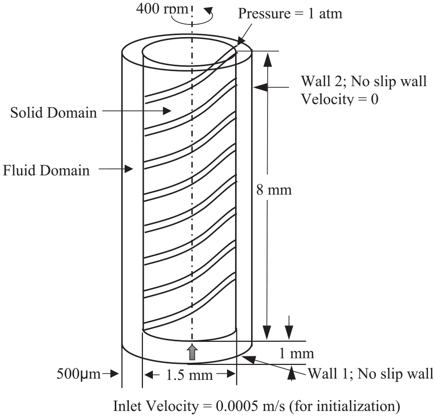
The boundary conditions and flow domain used for modeling.
Simulations were carried out for tool electrodes with helix angles from 25° to 60° in steps of 5°. A cylindrical volume with 1.6 mm diameter and 0.1 mm height was considered as the active machining zone. Debris was introduced in 0.5 fractions of the volume of all cells in this zone.
Results of simulation
The boundary conditions were set such that the outer surface of the flow domain was considered as a stationary wall and pressure outlet conditions were given. Transient simulations were carried out throughout for 0.5 s on tool electrodes with each helix angles having both single-helical and double-helical grooves and data was captured every 0.1 s.
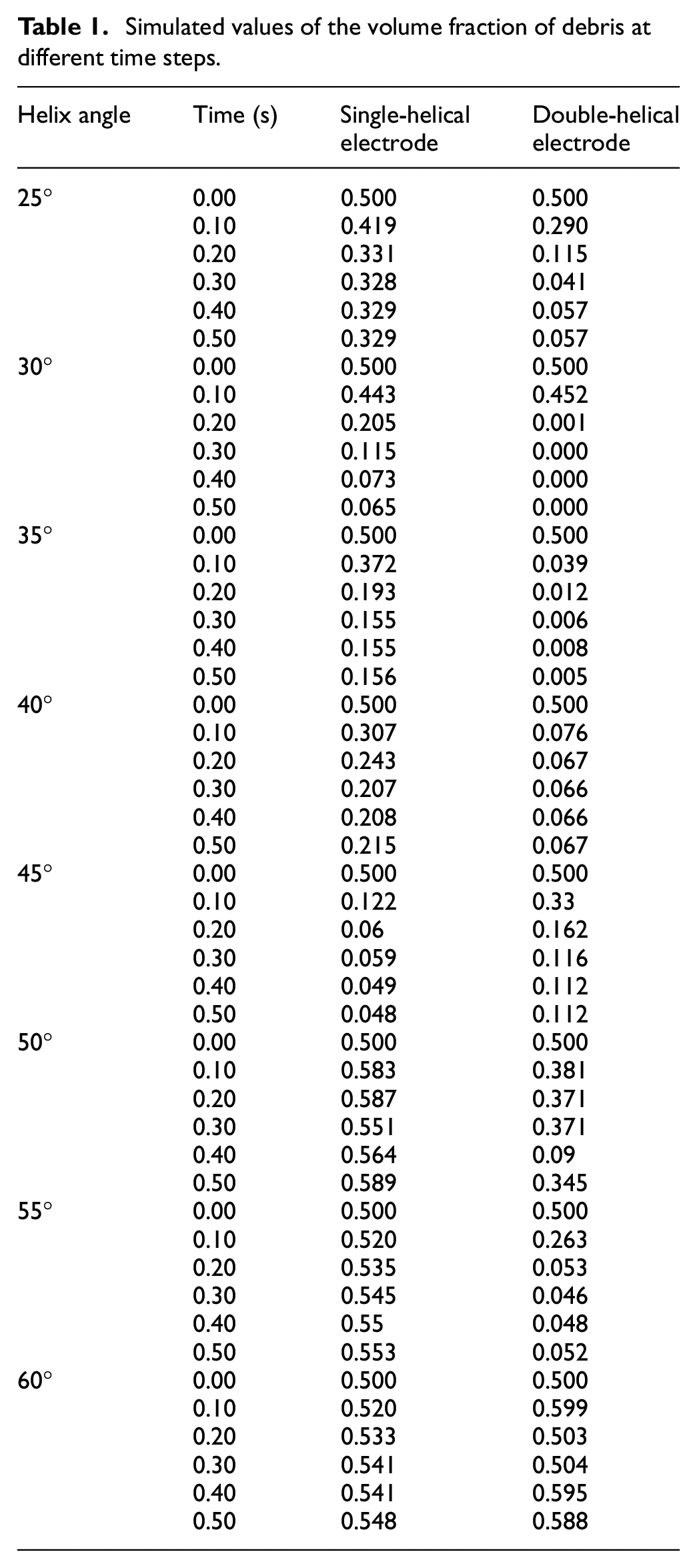
From Figure 4 the volume fraction of the debris in various cells in the flow domain at the end of simulation can be seen for both single and double-helical grooved tools. It can be observed that for larger helix angles of 50°–60°, there is an increased volume fraction of debris in each cell near and about the machining zone. This is due to the fact that as the helix angle increases, the debris particles have to travel longer distances before they can exit the flow domain. The maximum volume fraction of debris in the flow domain at various time steps for various helix angles is tabulated in Table 1 and the plots of the same are shown in Figure 5.
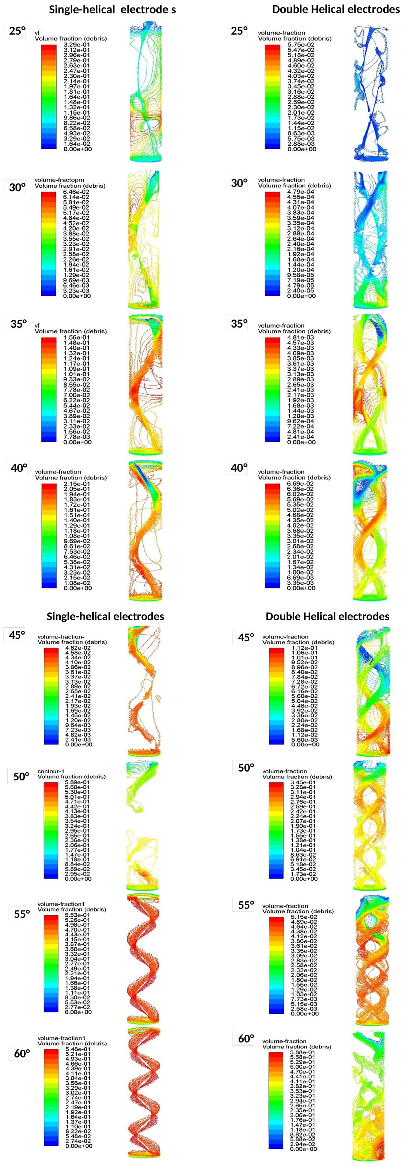
Plots of volume fraction of debris at 0.5 s time step for single and double-helical electrodes having various helix angles.
Simulated values of the volume fraction of debris at different time steps.
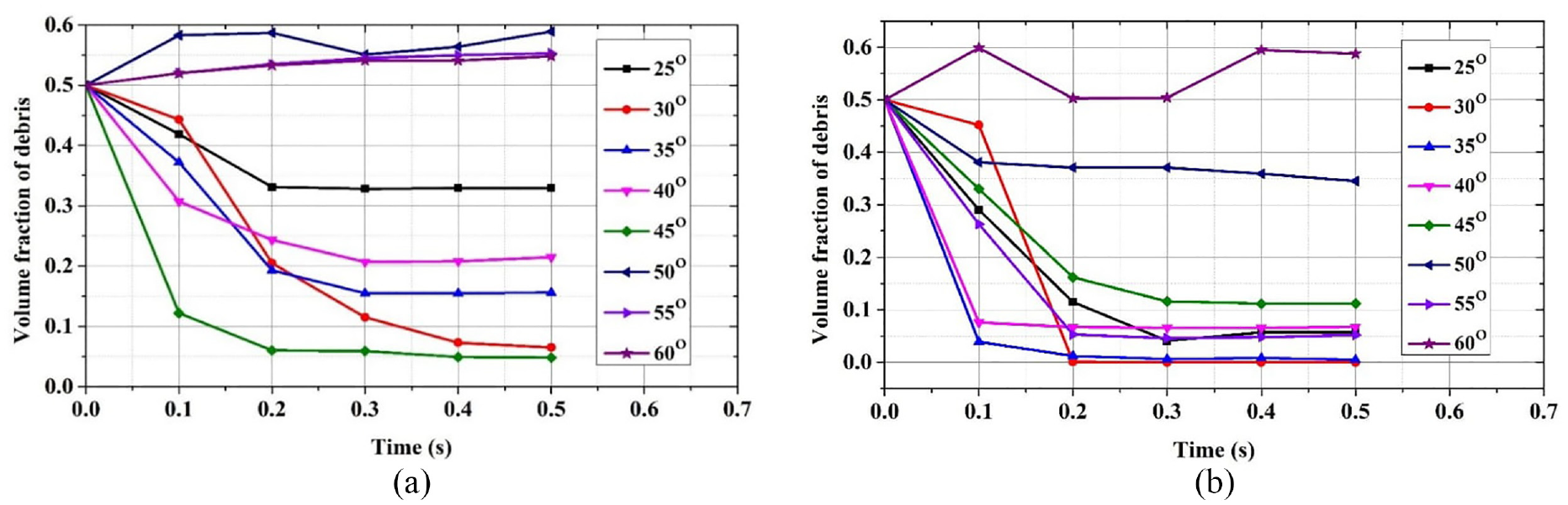
Plots of volume fraction of debris versus time at various helix angle for: (a) single-helical and (b) double-helical electrodes.
The plots of volume fraction at different time steps show that in the tool electrodes with helix angles 25° to 45° the volume fraction of debris decreases in each successive time-step. For the single-helical grooved electrodes, the best helix angles are 30°, 35°, 40°, 45° which is in agreement with the findings of Burek et al. 17 for studies on the effect of helix angle in chip removal during milling. And for the double-helical tools, the best helix angles for debris removal are 30°, 35°, 40°, 45°, 50°, 55°.
It can be understood that compared to the single-helical electrode, the double-helical electrode performs better in debris removal. At the time step of 0.2 s the maximum volume fraction of debris in the flow domain in all double-helical tools except the tools having helix angles 50° and 60° has reduced to fewer than 0.2. However in the case of single-helical tools, at the time step of 0.2 s the maximum volume fraction of debris in the flow domain has reduced below 0.2 only for the helix angles of 35° and 45°. From the simulations carried out four helix angles were selected to be machined on the EDD tools to carry out hole drilling experiments. For uniformity the same range of angles from 30° to 45° was chosen for both single and double-helical tools.
Machining of the tool electrodes
As described earlier three different types of EDD tools are developed; solid, single-helical and double-helical electrodes. A precision spindle developed by Janardhan and Samuel was set to impart rotational motion to the tool electrode as seen in Figure 6(a). 9
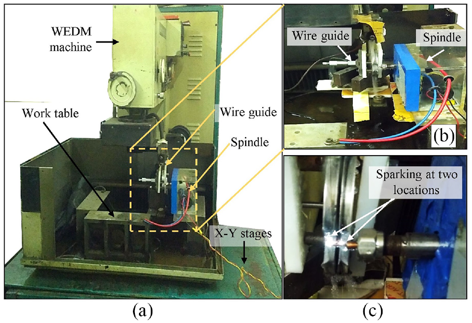
(a) Setup for machining of double-helical grooves, (b) wire guide and spindle set on machine table, and (c) sparking at two locations.
The double-helical grooved electrodes were machined by fixing the novel wire guide setup rigidly on a WEDM machine of electronica make along with the precision spindle as seen in Figure 6(b). All experiments were carried out at a rotational speed of 3 rpm and to obtain uniform micro grooves a constant depth of cut of 100 µm was set. During the process of double helix machining, sparks occur at two locations on the workpiece as can be seen in as seen in Figure 6(c). The feed rate was varied to obtain the required helix angles. Both single and double micro helical grooved EDD tools with helix angles of 30°, 35°, 40°, and 45° was developed as these angles were found to reduce debris accumulation as noted from the results of the simulation. Twenty-seven Copper electrodes having a diameter of 1.5 mm and a length of 8 mm are machined.
Scanning Electron Microscope (SEM) images of the machined electrodes are taken and the helix angle obtained is measured using ImageJ software. The marked helix angles of the single and double-helical grooved tool electrodes are shown in Figure 7. As the machining progresses due to many instabilities in the machining the feed rate slightly changes causing the pitch and helix angles at some parts to change from the required value. Figure 8 shows the top view of the three types of electrodes where the start of the helical groove can be seen. It is noticeable that in the double-helical grooved tools the starts of the helices are at diametrically opposite positions. For each of the helix angles as well as the solid tool three sets of tool electrodes were machined.
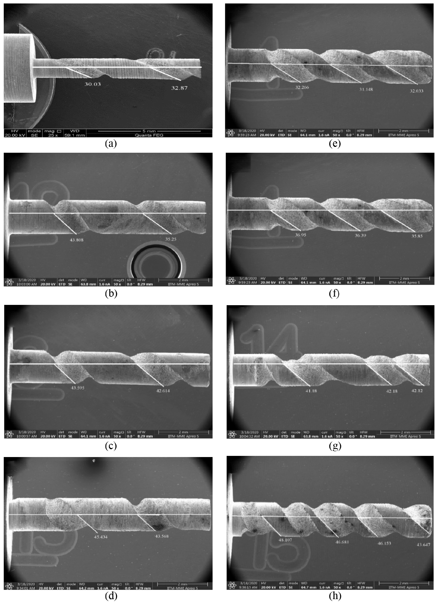
SEM images of single-helical electrodes with helix angles of: (a) 30°, (b) 35°, (c) 40°, (d) 45° and double-helical electrodes with helix angles of: (e) 30°, (f) 35°, (g) 40°, and (h) 45°.
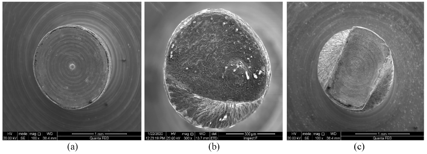
SEM images of the top view of: (a) solid, (b) single-helical, and (c) double-helical electrodes.
Experimental setup for performing EDD
The main purpose of these experiments is to drill holes on a Ti-6Al-4V workpiece using the developed electrodes and to compare the performance of the electrodes in terms of the hole quality. Electric discharge drilling was performed on a sparkonix EDD machine incorporated with a rotating head for fixing the tool electrode as well as a dielectric jet as shown in Figure 9(a). The developed tools were fixed to the spindle as seen in Figure 9(b).
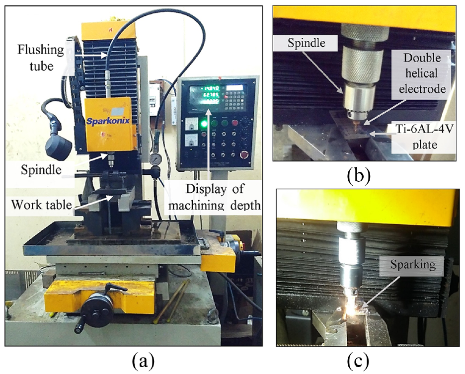
(a) Electric discharge drilling machine with a rotating head, (b) electrode and workpiece, and (c) sparking during electric discharge drilling.
The tool rotation imparts motion to the debris and allows it to be transported out of the drilled hole through the helical grooves. Material removal occurs by controlled sparking as can be seen in Figure 9(c). All experiments were carried out at a current of 25 A and 100 volts. The feed rate in the z-direction is given by adaptive control to maintain a constant spark gap. A constant flushing pressure and a rotational speed of 400 rpm were set for all experiments. The pulse on time and pulse off time were set to eight and nine machine units respectively which according to standard calibration ranges between 1.6 to 1.8 ms as this setting is seen to provide the best machining conditions.
The mode of flushing employed was jet flushing along the circumference as can be seen in the schematic diagram in Figure 10. The double helical grooves are provided to improve the debris removal by this mode of flushing and hence a comparison is done on the holes machined by solid, single helical and double helical electrodes using the same flushing method.
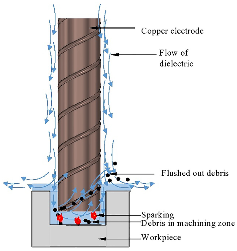
Schematic diagram of type of flushing used in EDD.
Results and discussions
Electric discharge drilling of 27 holes was carried out on a Ti-6Al-4V workpiece of 2 mm thickness using solid, single-helical and double-helical electrodes. Three trials were carried out to drill holes by each helix angles and the output parameters are tabulated in Table 2. The performance of the three types of tools were analyzed in terms of the machining time, Tool Electrode Wear Rate (TEWR), the hole diameter, hole taper angle and the spread of the recast layer.
Values of different output parameters of electric discharge drilling.
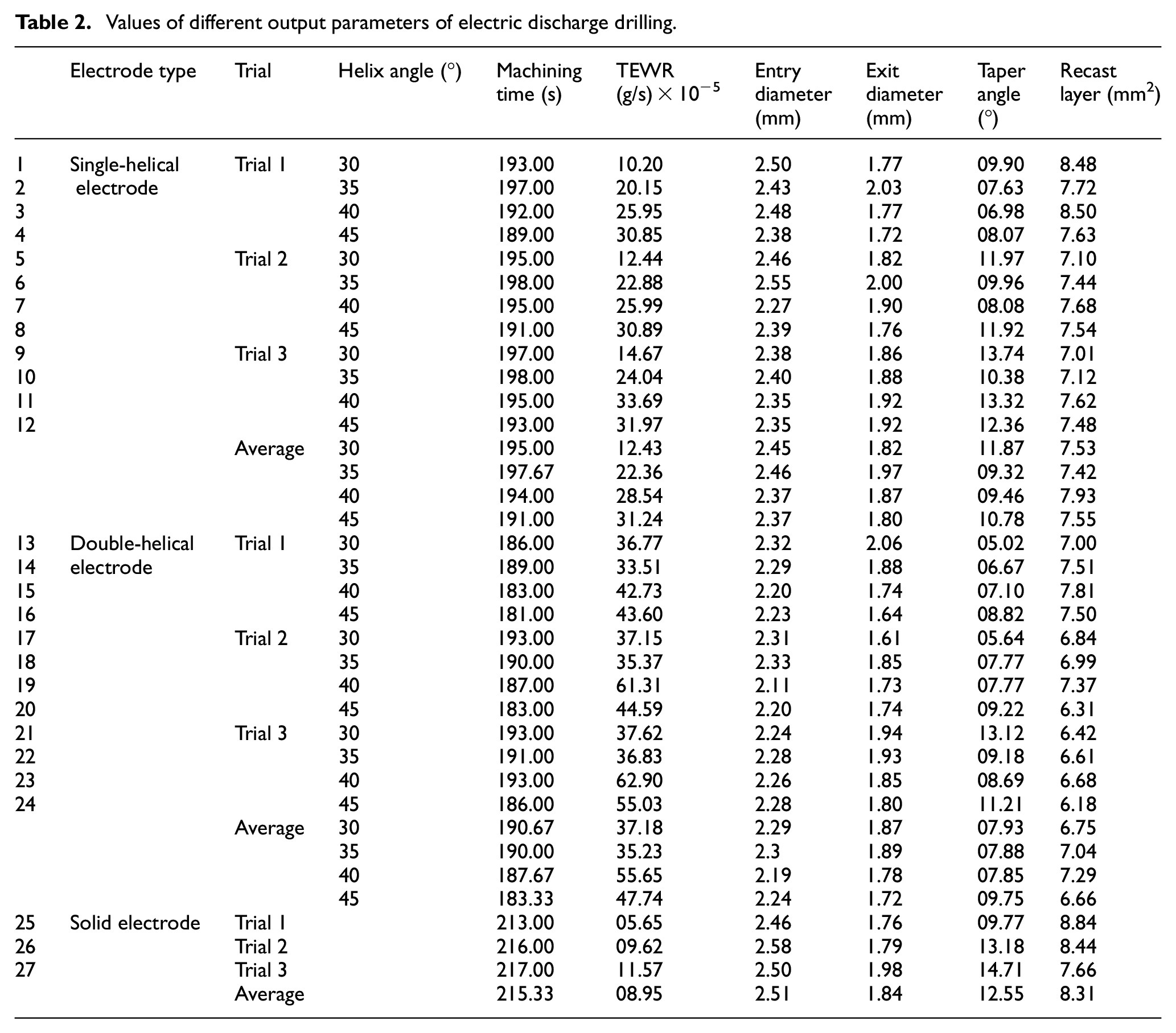
The machining time was measured with a stopwatch having a least count of 10 ms and was rounded off to the nearest second. Since the current was set at 25 A the machining time for all holes was lesser than 4 min. The electrode wear rate was calculated by weighing the electrode before and after machining on an electronic weighing balance having the least count of 1 mg.
Characterization of the machined holes
SEM images of the entry and exit of the holes were taken for characterization and analysis as shown in Figure 11(a). The diameter at the entrance and the exit was calculated by the method of least-square circle fitting.
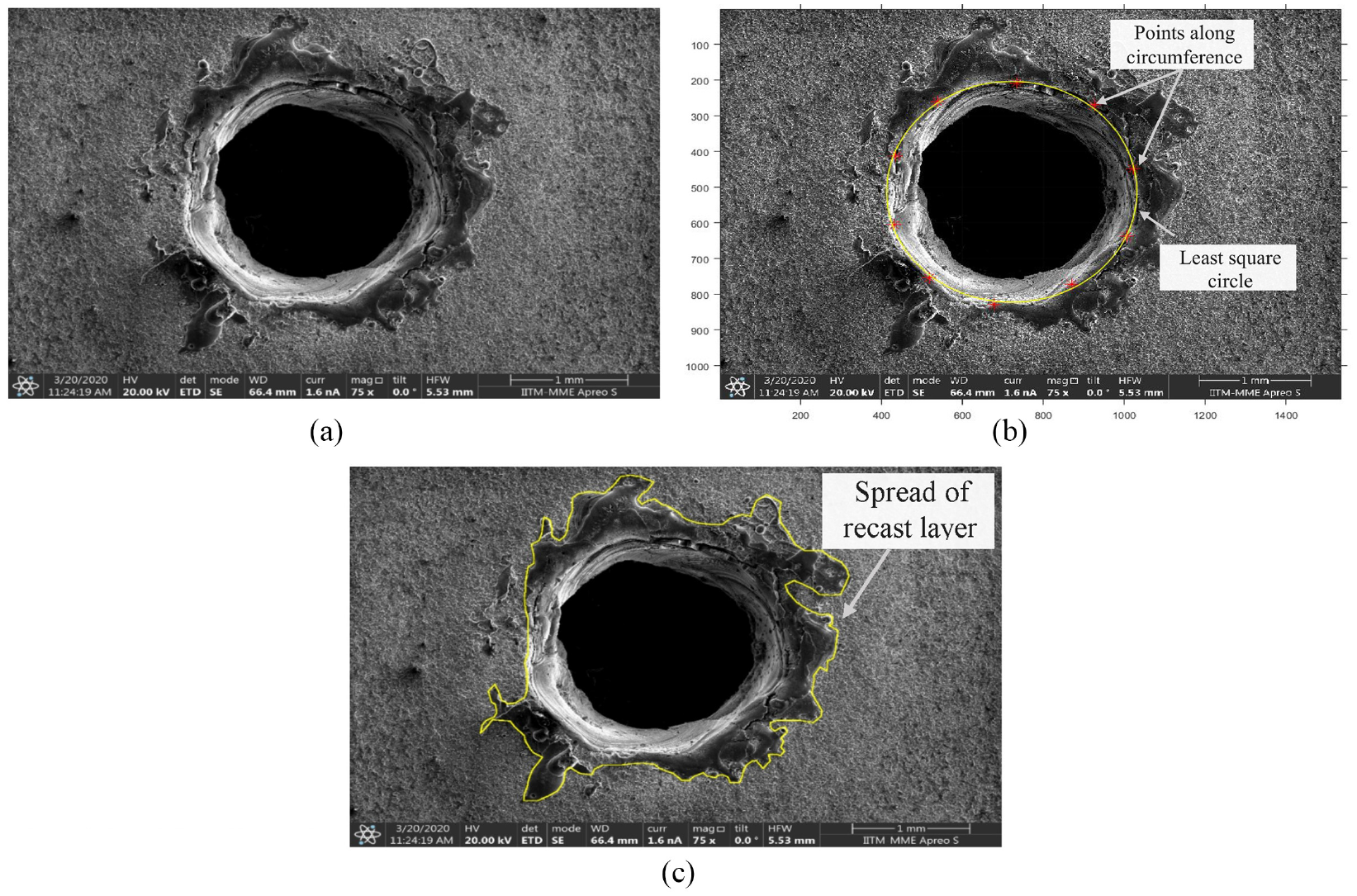
(a) SEM image of a hole drilled on TI-6Al-4V workpiece, (b) MATLAB plot showing measurement of diameter by least-square circle fitting, and (c) trace of recast layer.
Ten points were selected along the edge of the hole and the coordinates were obtained using a MATLAB code. A least-square circle was fit to the 10 points selected as shown in Figure 11(b) and the diameter of this circle is considered as the diameter of the hole.
Formula to find the least-square circle from coordinate data:
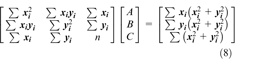
Where

The taper angle θ is calculated from
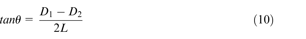
Where
In EDM though the heat affected zone is less the formation of the recast layer is one of the major drawbacks as it leads to poor surface quality and microcracks. 18 To calculate the area of the spread of the recast layer, the SEM image of the hole was imported into ImageJ software and pixel to mm conversion was done by setting the scale. Numerous points were selected close enough to capture the geometry of the recast layer and a polygon was constructed and its area is calculated as shown in Figure 11(c).
To analyze the effect of the helix angle the average value of the output parameters from the three trials was calculated and plotted against the helix angles. As the solid electrode is independent of the helix angle, it can be noted that it shows a constant value at all data points from all plots in Figure 12.
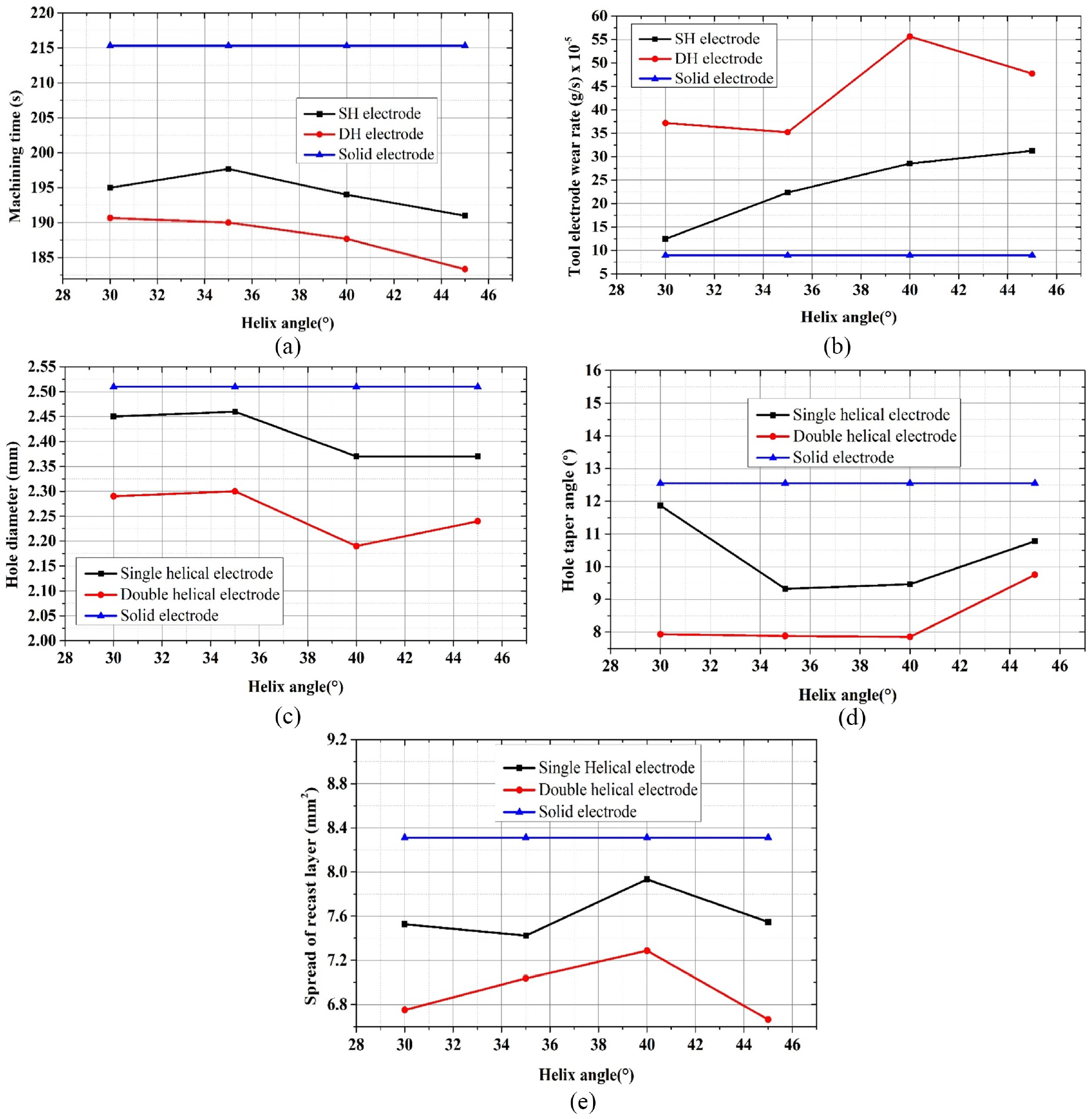
Plots of: (a) machining time, (b) electrode wear rate, (c) hole diameter, (d) hole taper angle, and (e) spread of recast layer when drilled with solid, single-helical and double-helical electrode at different helix angles.
Influence of the helix angle on machining time
From Figure 12(a), it can be observed that the solid electrode required the highest time to machine a through-hole followed by the single-helical grooved and the double-helical grooved electrode required the least time. The least machining time of 183.33 s is observed in the double-helical electrode with a helix angle of 45°. Machining time shows a decreasing trend as the helix angle increases from 30° to 45°.
Influence of the helix angle on TEWR
From Figure 12(b) it can be seen that the double-helical grooved electrode suffers the largest electrode wear rate. The highest average TEWR of 47.74 ×
Influence of the helix angle on overcut
From Figure 12(c) it can be noted that the holes drilled with all three types of electrodes have overcut as the dimension of the tool used was 1.5 mm. The highest overcut is produced by the solid electrode followed by the single-helical electrode with the least being in the holes drilled by using the double-helical electrodes. The least average diameter of overcut is 2.19 mm, seen on the hole drilled using the double-helical grooved electrode with a 40° helix angle. As the helix angle increases, the overcut diameter shows a slight improvement.
Influence of the helix angle on hole taper
The holes drilled using solid electrodes have the largest taper angles followed by the holes drilled by using the single and double-helical electrodes as can be seen in Figure 12(d). The taper rate is affected by the electrode size as well as the secondary discharges happening along the sidewalls of the hole. Since the double-helical grooved electrodes have the least curved surface area they produce fewer secondary discharges and hence the least taper.
Influence of the helix angle on the spread of the recast layer
In EDM recast layer and heat affected zone are inevitable. It leads to microstructural changes, grain growth, alternation of hardness, initiation of micro-cracks and changing the composition leading to deterioration of the surface integrity. 19 From Figure 12(e), it can be seen that the recast layer is highest on the surface of the holes drilled by using the solid electrode. This is because there is no channel for debris transportation.
The holes drilled using the double-helical grooved electrodes have the least recast layer due to efficient debris removal. The spread of the recast layer does not show any trend with the change of the helix angle.
The specimen are cut into two parts by wire EDM machining. The Surface topography inside the hole (as can be seen in Figure 13) shows that the inner surface of the holes has most debris deposition at smaller helix angles of 30° and 35° for single helical tools. Burs can be seen on the holes drilled with 40° and 45° with single helical tools. Large cracks can be seen on the hole drilled by double helical grooved tools at 30°. The hole drilled with the solid tool shows the largest burrs and uneven surface. The inner surface of the holes drilled with double helical grooved tools at 40° and 45° show lesser debris and burrs.
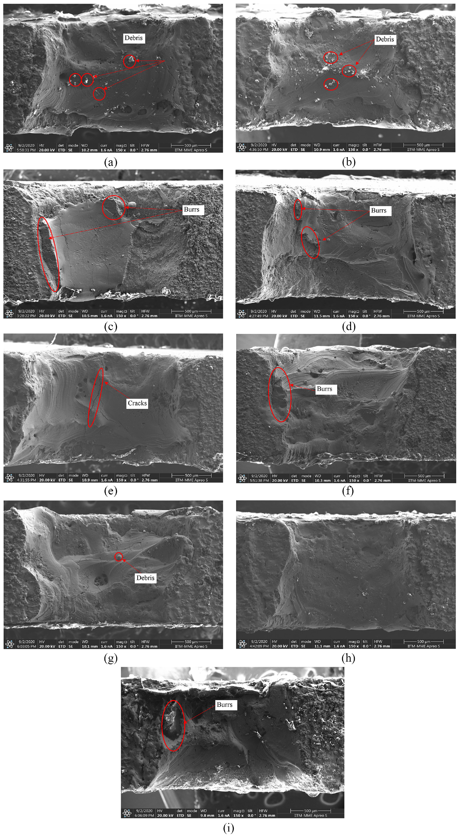
SEM images of the inner surface of holes drilled using single-helical electrodes with helix angles of: (a) 30°, (b) 35°, (c) 40°, (d) 45° and double-helical electrodes with helix angles of: (e) 30°, (f) 35°, (g) 40°, (h) 45°, and (i) solid electrodes.
Influence of the helix angle on surface topography
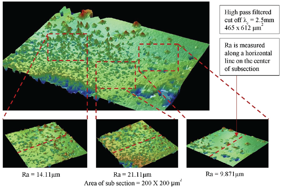
The surface topographies of the machined samples are obtained using a Veeco 3D optical surface profiler. For each sample, a 465 × 612 µm2 section is scanned following which three subsections of approximately 200 µm2 are taken and the curvature and tilt are filtered out using the high pass filter settings.
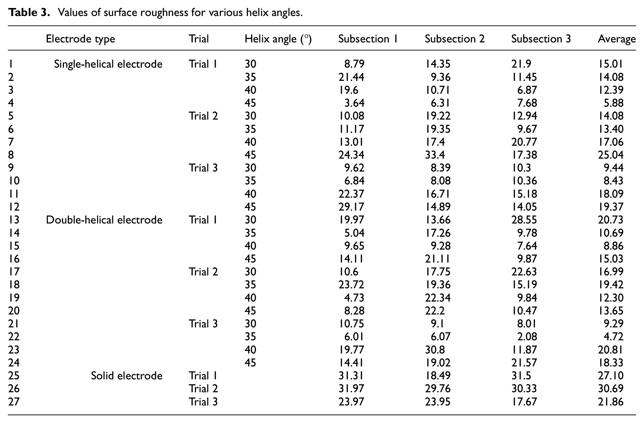
The Ra value corresponding to a centerline on the subsection is considered. The average of the surface roughness from these three subsections is considered as the Ra of the sample. The measure values can be seen in Table 3 and an illustration of how the subsections are taken is shown in Figure 14. The surface roughness plot shown in Figure 15 shows that helix angles do not have a commendable effect on the surface roughness. However, it can be seen that the surface roughness tends to increase with an increase in helix angles and the double helical tool provides a relatively better surface finish. This is in agreement with the findings of Liu et al. 18 wherein a helical grooved electrode with added Silicon Carbide particles is used to obtain an improved surface finish.
Values of surface roughness for various helix angles.
Topography of the inner surface of the drilled holes.

Plot of surface roughness of the inner surface of holes at various helix angles when drilled using solid, single helical and double helical electrodes.
It is seen from section 6.2 that the machining time decreases with increase in helix angle from 30° to 45°. The axial and radial components of the flow velocity of the dielectric fluid in the helical grooves become equal at 45°. This phenomena in EDM drilling is analogous to the chip evacuation velocity observed in milling. 20 At smaller helix angles, the axial component of the flow velocity is higher and does not aid in debris transport. Hence the double-helical grooved electrode with 45° performs best when machining time is considered. This concept was also observed by Hung et al. 13 while performing step turning, the machining time was substantially reduced by using a single helical electrode. With the double helical grooves as well as the increase in helix angle the machining time, overcut and spread of recast layer are lesser as seen in section 6.6 and 6.4, however from section 6.3 it is seen that the TEWR increases. For double helical tool and larger helix angles the core of the electrode is weaker and has lesser material at any given cross-section, leading to larger electrode wear rate. Such phenomenon was also observed by Kumar et al., 10 where a double notched electrode is seen to have a larger tool wear rate when compared to single notched and solid electrode. The reduction of the overcut and spread of recast layer are in agreement with the observations of Puranik and Joshi, 5 wherein it is reported that the debris particles cause secondary discharges and oversized holes when not flushed away from the machining zone. It can be noted from section 6.5 that at 45° the hole taper angle is larger. As seen in Figure 12(b) the TEWR is higher at 45° which causes the tool to develop a tapered profile. From section 6.7 it can be seen that, the surface topography and surface finish are improved with the double helical tool. This is in alignment with basic principles seen in most of the literature in this field and particularly with the observations of Liu et al. 18 where it is reported that the use of a helical tool for grinding a machined hole leads to good surface finish.
Conclusions
The comparison and analysis of the performance of solid, single-helical and double-helical electrodes in electric discharge drilling in Ti-6Al-4V are presented in this article. A novel process and method are designed and developed to manufacture EDD tools in a single pass. To understand the transportation if debris from the machining zone through the helical grooves better, a CFD simulation is carried out. The key findings from the characterization and analysis carried out are listed below.
The double-helical grooved tool requires the least machining time with the least reported average machining time of 183.33 s at 45°. The machining time reduces as the helix angles are increased to 45° as the radial component of the flow velocity increases allowing the debris to be smoothly picked up from the machining zone.
The highest TEWR is reported on the double-helical tool with a value of 47.74 ×
The double-helically grooved tools produce the least overcut. The least hole diameter observed is 2.19 mm for the 1.5 mm double-helical tool with a helix angle of 45°. The overcut is lesser at 40° and 45° due to better debris removal.
The least value of the hole taper angle is seen in holes drilled using the double-helical tools with smaller helix angles.
The double-helical grooved tool produces the least recast layer since it provides a channel for the debris to be transported away from the machining zone.
The SEM images show that the largest burs and debris accumulation is observed on the inner surface of the holes drilled using solid tool. The single and double helically grooved tools also lead to burs and cracks but a comparatively cleaner surface is obtained with the double helically grooved tool with 45° helix angle.
It can be concluded that the micro double-helical grooved electrode performs better in debris removal and its transportation from the machining zone. However, reduced machining time, overcut, hole taper and area of recast layer are obtained at the cost of increased TEWR. The double-helical grooved tool developed has the potential to be used in various applications of high aspect ratio hole drilling.
Footnotes
Appendix
Author’s note
The authors have provisionally filed a part of this research idea for an Indian patent under the application number “201841047112.”
Declaration of conflicting interests
The author(s) declared no potential conflicts of interest with respect to the research, authorship, and/or publication of this article.
Funding
The author(s) disclosed receipt of the following financial support for the research, authorship, and/or publication of this article: This research was supported by the Industrial Consultancy and Sponsored Research (IC&SR) at IIT Madras under the innovative projects scheme, Grant number: ICS/18-19/832/RFIE/MAHS.