
Abstract
In ultrasonic-assisted wire electrical discharge turning, the longitudinal ultrasonic vibration of the wire creates a longitudinal compressive and rarefaction wave front, which is successively aiding very violent and accelerative mass to transfer across the spark gap, acting as a pump, causing higher debris suspension and evacuation from the gap and higher dielectric fluid renewal. For this purpose, a specially designed and fabricated turning spindle is used. An auxiliary device which produced the ultrasonic vibration was installed between the two wire guides. The ultrasonic system consists of an ultrasonic generator, a transducer, and a wire holder. When the wire is being driven, the transducer and the wire holder are vibrated under the resonance condition. In this study, the size of eroded craters, surface roughness, recast layer thickness, and micro-crack, measured on the workpiece (anode) were found to be highly influenced by the applied ultrasonic vibration. It was found that the volume of the eroded craters increased by applying the ultrasonic vibration based on single discharge analysis. This means that the remaining lower melting material leads to the reduction of the recast layer thickness and micro-cracks. Based on the obtained results, in this process, the surface roughness is not changed under low discharge energy (finishing condition).
Introduction
Electrical discharge machining (EDM) is a thermoelectric process that erodes workpiece materials by a series of discrete electrical spark between the workpiece and an electrode flushed by or immersed in a dielectric fluid. The hardness and strength of the difficult-to-machine work materials are no longer the dominating factors that affect the tool wear and hinder the machining process. This makes the EDM process particularly suitable for machining hard, difficult-to-machine materials. 1 The EDM process has the ability to machine precise, complex, and irregular shape with a computer numerical control system. In addition, the cutting force in EDM process is small, which makes it ideal for fabricating miniature parts. 2
Several researchers have reported that ultrasonic-assisted EDM of steel improves discharge characteristics.3–5 The advantages of using a vibrating tool with EDM relate to the removal of debris from the spark gap and the consequent improvement in material removal rate (MRR). It is also suggested that there is a reduction in the thickness of the recast and heat-affected layer together with the number of associated micro-cracks. 3 Lin et al. 4 have pointed out that EDM of titanium alloy by using ultrasonic tool vibrations give higher MRR and eliminate the recast layer. Abdullah and Shabgard 5 observed that in die-sinking EDM, application of ultrasonic vibration significantly reduces arcing and open circuit pulses, and the stability of the process had a remarkable improvement.
In the wire electrical discharge turning (WEDT), electrical discharges take place between the traveling wire and the rotating workpiece. 2 In this work, the ultrasonic vibrations are applied to the wire passing through wire guides. A wire guiding block is employed to transfer the ultrasonic vibrations to the wire, and at the same time, the deflection of the wire is prevented to maintain the gap distance between the wire electrode and the workpiece. In ultrasonic-assisted wire electrical discharge turning (USWEDT), the ultrasonic vibration causes a relative sliding motion between the wire and the workpiece, which, in turn, made discharge column slide on the workpiece. Sliding of discharge plasma channel across the electrodes will be possible if there is a relative high speed between the electrodes, depending on the speed. According to Kunieda and Kameyama 6 study, the plasma discharge column slides easier over the cathode compared with anode. They carried out the heat conduction analysis and found that in areas where the sliding speed is small, the material removal volume of the electrode increases with increasing sliding speed. Weingärtner et al. 7 investigated the influence of high-speed rotating workpiece in WEDT. The slip of the center point of the discharge column was measured and found to match the theoretical slip. Qu et al. 8 evaluated the MRR of cylindrical wire electrical discharge machining (WEDM) parts by proposing a mathematical model. In another work, they evaluated the surface integrity of cylindrical WEDM parts by proposing a mathematical model. An estimation of the surface finish and roundness of cylindrical WEDM parts was presented by using the model. This study investigated the surface integrity and roundness of cylindrical WEDM parts and explores possible ways to adjust process parameters in order to achieve better surface integrity and roundness. 9 Rhoney et al. 10 have studied the feasibility of using cylindrical WEDM for dressing a rotating metal bond diamond wheel used for precision in grinding of ceramics. Mohammadi et al. 11 studied the surface roughness and roundness in the WEDT by statistical analyses. Haddad and Fadaei Tehrani12,13 investigated the roughness, roundness, and MRR of turning parts via the cylindrical wire electrical discharge turning (CWEDT) process and explore possible ways to adjust its parameters to achieve better roundness by statistical methods. The experiments are employed in this study to consider the effects of machining parameters on MRR, surface roughness (Ra), and roundness. This was done using the technique of design of experiments and techniques such as response surface methodology (RSM) for regression analysis. Taguchi’s robust design methodology is proposed for optimization of CWEDT operation, and the effects of machining parameters such as power, pulse-off time, voltage, and spindle rotational speed have been investigated on MRR, surface roughness, and roundness by Taguchi approach. 14 Janardhan and Samuel 15 have developed a pulse discrimination algorithm for classifying the discharge pulses into open circuit, normal, arc, and short circuit pulses. With the help of algorithm, the number of arc regions, average ignition delay time, and the width of the normal and arc regions in thedataacquired can also be obtained. They reported that MRR is less in WEDT, the number of arcs and arc regions are more in WEDT, and the surface roughness and roundness error of the WEDT components are influenced by the occurrence of arc regions, width of arc, and normal discharge regions and average ignition delay time. The WEDT process was modeled using an artificial neural network with feed-forward back-propagation algorithm and using adaptive neuro-fuzzy inference system. Using this method, required input parameters can be selected to achieve higher MRR and good surface finish. 16 Abdullah et al. 17 presented that the amount of recast layer, the size of the heat-affected zone (HAZ), and the size of cracks of the machined workpiece in the EDM process were reduced by the ultrasonic vibration of the copper tool. Although the surface roughness was increased slightly, the surface integrity of WC-Co could be improved in ultrasonic-assisted EDM. Introduction of ultrasonic vibration on WEDM resulted in applying the greater peak current and increasing the cutting rate. 18 In addition, by using the combined technology, the surface integrity would be improved. Some studies have been conducted to investigate the WEDT process. In addition, most of the researchers have used the ultrasonic vibration to improve normal die-sinking EDM process, but hardly any information is available about the process characteristics when the ultrasonic vibration is applied in WEDT process.
In this work, discharge crater volume for relative speed resulting from the ultrasonic vibration of the wire (in axial direction) under various machining conditions was evaluated. An induced ultrasonic vibration normal to the relative-speed direction increases the amount of material removed per discharge. It is expected that an increase in material removal per discharge (while the discharge energy is constant) will be able to reduce the thickness of the recast layer and decrease the micro-cracks. Surface roughness is increased slightly.
Experimental setup
In this study, all experiments were conducted on a five-axis ONA R250 WEDM machine with a resistor–capacitor (RC) pulse generator. A rotary axis for rotating a round workpiece and an ultrasonic head for vibrating the wire electrode were added to the machine. A wire holder transferring the ultrasonic vibration to the wire is installed between the two wire guides of the machine. The wire holder is vibrated by an ultrasonic transducer through an ultrasonic titanium horn. The wire holder is vibrated in the direction along the rotational axis of the workpiece by the transducer (Figure 1).
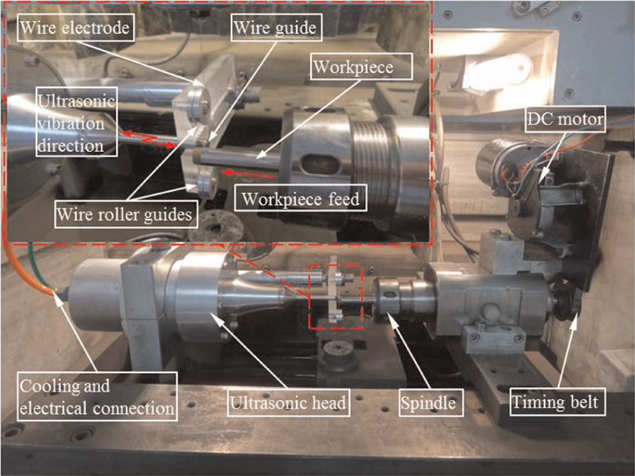
Setup for experiments.
In these experiments, a brass wire of Bercocut with a diameter of 0.25 mm was used. The workpiece electrode was a high-speed steel (HSS) round piece of 24 mm diameter. It was round ground with a fine-grained grinding wheel, to allow for a good surface quality to facilitate subsequent measurement of eroded craters.
The wire-vibration amplitude was set at 12.5 µm. However, it could be adjusted by the output power of the generator driving the transducer. The best possible choice was 200 W. For ultrasonic output powers of less than this value, the ultrasonic effect is negligible. Higher powers than this cause short circuit and wire breakage, so the process will be interrupted. The wire is vibrated by the wire holder which was directly connected to the concentrator horn. The shape of the eroded craters was measured using an optical three-dimensional (3D) measurement device (confocal scan microscopy (CSM) 3D microscope). The discharge duration time was measured using a 100 MHz oscilloscope-type CombiScope-HM1008. Electrical discharges between the wire and the workpiece are supplied by capacitors. Here, the discharge duration time depends on the stored electrical energy of the capacitors and how fast it can be delivered after the breakdown phase. The corresponding discharge duration time was te = 2 µs.
Result and discussion
Influence of the ultrasonic vibration on the shape and volume of the eroded crater
In this work, single discharge experiments were carried out using typical WEDT parameters. In Table 1, the erosion and technological parameters applied in the experiments are summarized. The ultrasonic vibrations were applied for two different peak currents in different relative rotational speeds.
Set of parameters used on single discharge experiments on ONA R250 wire EDM.
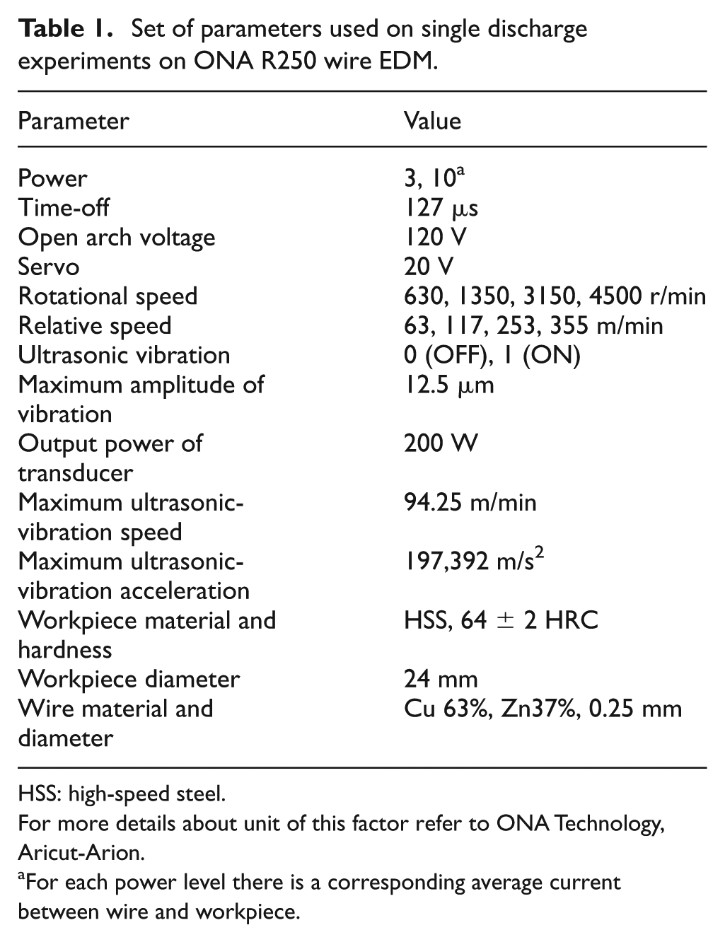
HSS: high-speed steel.
For more details about unit of this factor refer to ONA Technology, Aricut-Arion.
For each power level there is a corresponding average current between wire and workpiece.
The relative speeds of the workpiece and wire were selected high enough, and the discharge interval time (pulse-off time) was set at longest possible value (127µs) so that the consecutive discharge spots on the workpiece surface could be separated far enough for accurate measurements and evaluations. The ultrasonic vibrations were applied for two different peak currents in different relative rotational speeds.
It can be seen that, although the maximum relative vibration speed of ultrasonic given to the wire is in the order of relative speeds generated by workpiece rotation, the ultrasonic vibration, due to high ultrasonic-vibration acceleration and long period of ultrasonic compared with the discharge duration, has a significant influence on the shape of the eroded craters. The plasma discharge column slides over the workpiece (anode), creating deformation of craters in the vibration direction. In Figure 2, the typical results obtained by applying the ultrasonic vibration (power = 10 and relative speed Vr = 63 m/min) are shown. The crater always extends along the relative motion, whether it is from the ultrasonic or from the rotation of the workpiece. As an example, without ultrasonic vibration, when the relative rotational speed, Vr = 63 m/min and power, P = 10 are applied, the ratio of major diameter to minor diameter is 1.398. When the ultrasonic vibration of the wire is used, this value is reduced to 1.286. Based on Figure 2, it can be stated that, upon using relative motion by the ultrasonic vibration, the plasma discharge column easily slides over the workpiece (anode) in the direction of the ultrasonic vibration. This means that the crater surface area is increased, and for a certain amount of energy per discharge (average discharge voltage × average discharge current × discharge duration), the crater becomes deeper. According to Uhlmann et al., 19 a relative speed between workpiece and tool electrode influences the electrical discharges and results in elongation of discharge craters on the cathode.
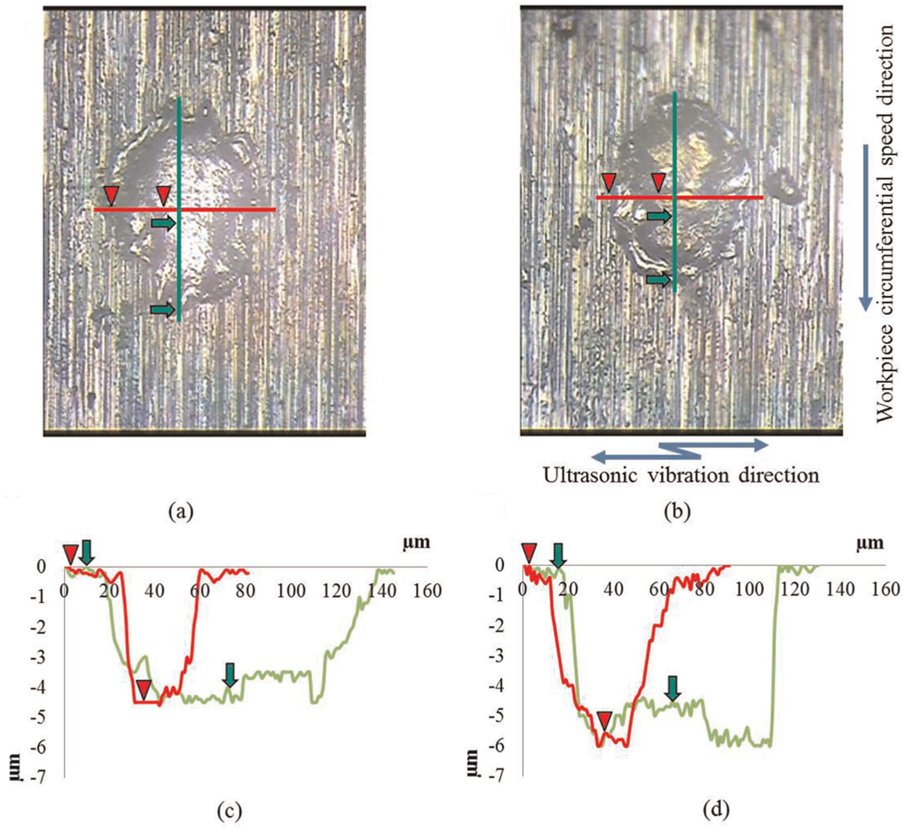
Deformed discharge craters with sectional profile of the crater on the workpiece in single discharges without (a and c) and with (b and d) ultrasonic vibration (P = 10, Vr = 63 m/min).
The eroded craters were further evaluated, and their volumes were calculated using an optical 3D measurement device (CSM 3D microscope). The results obtained by applying power of 10, without ultrasonic vibration, are presented in Figure 2(c). In Figure 2(d), the craters when the ultrasonic vibration was used are shown. It is found that although the length of the crater is reduced by the ultrasonic vibration, the material removal per discharge, due to an increase in the width and depth of the crater, is increased. Calculation of the volumes shows that under higher relative rotational speed, the material removal per discharge is higher.
In Figure 3, the results of the calculations of the volume removed per discharge are summarized. It is observed that the ultrasonic vibration has a dramatic influence on the removed material per discharge. This phenomenon proves the compressive and repulsive effects of the ultrasonic vibration added to the ordinary melting and the bulk boiling of material within the crater under plasma. 20 It is expected that the increasing of the material removal per discharge (when the discharge energy was constant) can reduce the recast layer and decrease the micro-cracks.
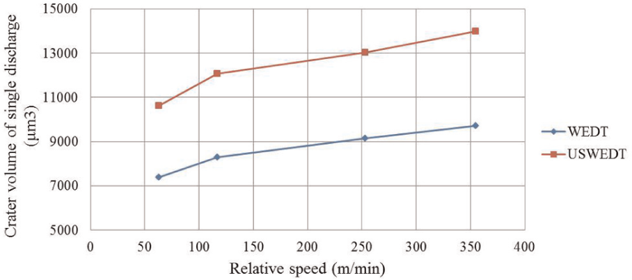
Material removal volume per single pulse discharge in practical machining conditions (P = 10).
Influence of the ultrasonic vibration on the surface roughness and subsurface of cylindrical workpiece
In this experiment, according to primary tests accomplished on HSS specimens by the authors using ONA Aricut R250 technology manual and user’s guide, the parameters in Table 2 are used to investigate the ultrasonic-vibration effect on the surface roughness (Ra) and the subsurface of workpiece. The surface roughness (Ra) was measured by using a measuring device (Mahr M2 Perthometer).
Set of parameters in the experiment on ONA R250 wire EDM.
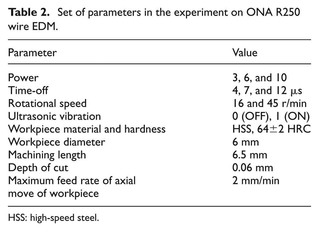
HSS: high-speed steel.
In this experiment, a mixed-level design of 22× 32 was applied. Subsequently, 36 experiments were randomly carried out by using the parameter levels. All the main effects and factor interactions could be estimated by this factorial design.
Analysis of variance (ANOVA) is used here to test the null hypothesis with regard to the data gained through experiments. Table 3 shows ANOVA results for surface roughness. In this table, DOF denotes degree of freedom, and sequential sum of squares and adjusted mean squares are, respectively, designated by Seq. SS and Adj. MS. In this study, confidence level was chosen to be 95%. So the p-values which are less than 0.05 indicate that null hypothesis should be rejected, and thus, the effect of the respective factor is significant.21,22 It can be seen from Table 3 that the surface roughness is influenced by the power, the ultrasonic vibration of the wire, the time-off, and the rotational speed. According to the quantity R2, about 97.91% of the variability in the surface roughness can be explained by these factors. The number of factors in the model is 81.69% estimated by the adjusted R2 (adj. R2). 21
Analysis of variance for surface roughness (Ra, µm), using adjusted SS for tests.
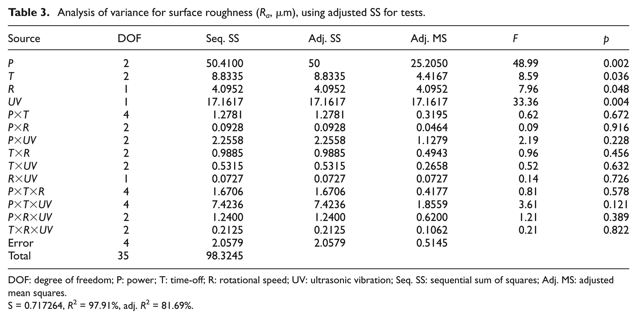
DOF: degree of freedom; P: power; T: time-off; R: rotational speed; UV: ultrasonic vibration; Seq. SS: sequential sum of squares; Adj. MS: adjusted mean squares.
S = 0.717264, R2 = 97.91%, adj. R2 = 81.69%.
The graphical evaluation of the machining parameters’ effects on the surface roughness is shown in Figure 4. Also, as it can be seen in Figure 4(a), the surface roughness (Ra) is increased from 3.193 to 4.631 µm by applying the ultrasonic vibration.
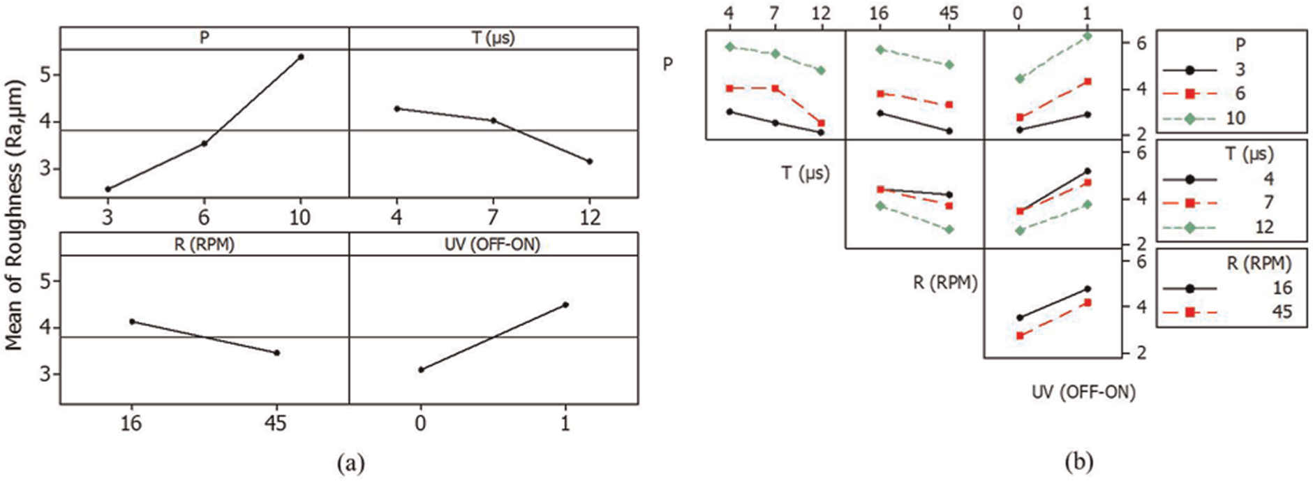
(a) Main effects and (b) interaction plots for the surface roughness (Ra, µm).
In order to investigate the effect of the ultrasonic vibration in finishing and roughing conditions, Levels 3, 6, and 10 of power were selected. According to the manufacturer’s manual, levels from 0 to 7 are used for finishing, while levels from 8 to 15 are used for roughing. In Figure 4(b), it is shown that the surface roughness is affected by the ultrasonic vibration in both finishing and roughing conditions. The surface roughness (Ra) is increased from 2.226 to 2.937 µm in finishing condition and from 4.564 to 6.531 µm in roughing condition; therefore, in finishing conditions (using low power), the surface roughness (Ra) is to be increased slightly in USWEDT. Therefore, low levels of the power and high levels of the rotational speed and time-offs achieved by applying the ultrasonic-vibration result in a lower Ra along with a higher MRR.
A schematic representation of the experimental setup is shown in Figure 5. As the discharge duration is 2 µs, pulse-off time is 7 µs, and each half period of the ultrasonic vibration is 25 µs, there are two distinguishable expected conditions for discharge plasma, as it is shown in Figure 6. If discharge takes place when the wire-vibration displacement is 0, the discharge channel will experience maximum speed. If wire-vibration displacement is at the maximum value, then the evacuation or compression forces within the plasma will be at maximum. If the wire is moving from the extreme vibration amplitude toward the zero displacement position, the forces will be compressive with acceleration of about 1,97,392 m/s2, which delay the molten material boiling and reduce normal spark type, as it is shown in Figure 6(a). However, as the impact force is imposed on the surface of molten crater, due to the ultrasonic vibration of the wire, it is expected that the induced pressure forces the molten material to be out of the crater and results in removing of the material from the crater. On the other hand, if the wire is moving toward the extreme vibration amplitude, the molten material evacuation inside the crater will be carried out by these forces; therefore, higher explosive bulk boiling of molten material will be done and the normal spark type will be increased, as it is shown in Figure 6(b). In this way, the amount of the material removed from the crater is being increased. 17
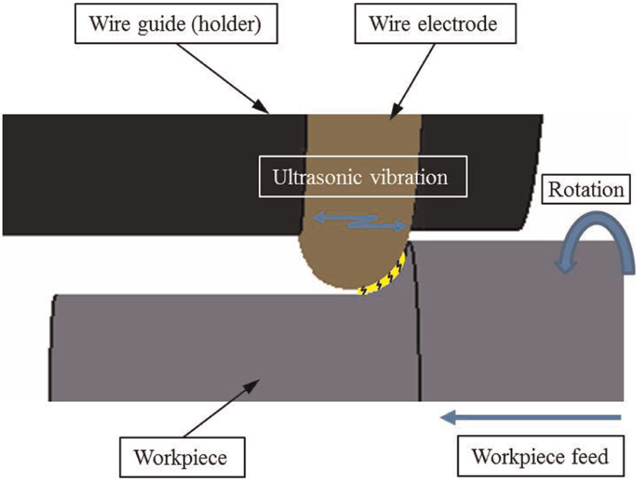
Schematic representation of the experimental setup for performing USWEDT tests.
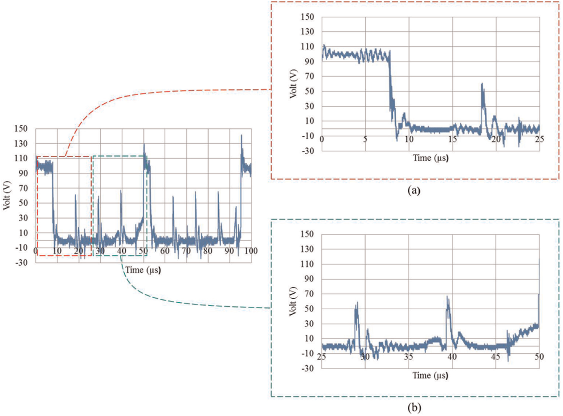
Sample of the voltage-pulse series in USWEDT: (a) the wire is moving toward the workpiece and (b) the wire is moving from the workpiece (power: 6, time-off: 7 µs, rotational speed: 45 r/min).
In the EDM process, applying low current and short duration pulses, the energy of the sparks and the volume of molten and resolidified material will become low, resulting in lower thermal stresses and fewer cracks on the surface layer. When the discharge energy value is at average or high point, the molten and resolidified material volume is bigger, and this leads to higher thermal stresses that resulted in transverse and normal cracks on the surface layer.23,24.
In the ultrasonic-assisted EDM process, compared to the conventional EDM, the MRR is higher as the ultrasonic waves allow a lower volume of resolidified material to be left in each crater; therefore, lower thermal stresses and fewer cracks on the surface layer are to be expected.17,25 In the WEDT process, the thermal waves of the sparks and a very rapid quench rate of the heated material in the plasma contact zone are the main reasons for the appearance of the micro-cracks, as these are shown in Figure 7(a) in low power and in Figure 8(a) in high power. In the USWEDT process, the MRR is higher than the MRR in the conventional WEDT. It is due to the ultrasonic waves resulting in leaving lower volume of resolidified material in each crater. In this case, it is expected that the recast layer will be lower, and the micro-cracks on the surface layer will be fewer. The thickness of the recast layer is reduced from 6.58 to 2.11 µm in finishing condition and from 17.9 to 5.79 µm in roughing condition, and also the amount of the recast layer is decreased in both roughing and finishing conditions by applying the ultrasonic vibration. As these are shown in Figures 7(b) and 8(b), the ultrasonic vibration can reduce the recast layer and micro-cracks in WEDT.
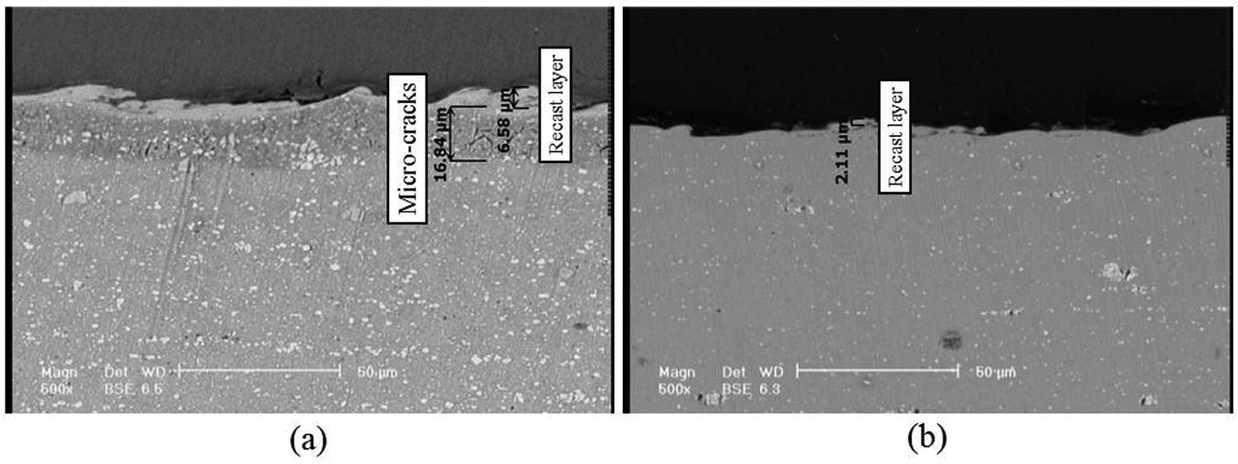
SEM micrograph of the workpiece cross-section (power = 3, time-off = 4 µs, rotational speed = 45 r/min): (a) WEDT and (b) USWEDT.
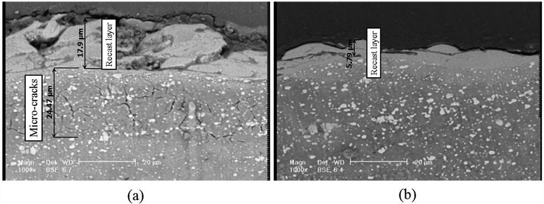
SEM micrograph of the workpiece cross-section (power = 10, time-off = 4 µs, rotational speed = 45 r/min): (a) WEDT and (b) USWEDT.
Conclusion
In this study, the authors reviewed influences of the ultrasonic vibration on the discharge column behavior acting on the workpiece surface. The single discharge was evaluated in different relative rotational speeds with and without employment of the ultrasonic vibrations. To investigate the effects on crater geometry and volume, the width, length, and depth of the discharge crater on workpiece were studied. Also, in this work, the evaluation of the effects of the ultrasonic vibration on the surface roughness, recast layer, and micro-cracks was conducted.
The main conclusions are as follows:
The length of the crater is decreased by the induced ultrasonic vibration normal to the relative-speed direction, whereas the width and the depth of the crater are increased. The amount of the material removed per discharge by applying the ultrasonic vibration can be increased.
It is expected that the thickness of the recast layer and the depth of the HAZ could be reduced by an increase in material removal per discharge (while the discharge energy was constant).
It is observed that using the ultrasonic vibration in WEDT was an efficient method to improve surface integrity and results in a higher MRR. Therefore, the MRR has been increased significantly by applying the ultrasonic vibration, while the recast layer thickness and micro-cracks are decreased.
A lower surface roughness (Ra) along with a higher MRR can be achieved by choosing low levels of the power and high levels of the rotational speed and time-off attained by applying the ultrasonic vibration.
Decreasing the recast layer and micro-cracks in USWEDT is shown in the scanning electron microscopy (SEM) micrograph analysis. It is mainly attributed to the dispersion of more molten material out of the crater resulting in the thermal and tensile stresses reduction achieved by applying the ultrasonic vibration.
Footnotes
Declaration of conflicting interests
The authors declare that there is no conflict of interest.
Funding
This research received no specific grant from any funding agency in the public, commercial, or not-for-profit sectors.