
Abstract
An experimental comparison of cutting fluid delivery nozzles was carried out with application to profile creepfeed grinding. A novel method of nozzle design and development involving rapid-prototyping enabled an exhaustive experimental approach. Circular, rectangular, and elliptical orifice nozzles were compared in terms of workpiece profile error, workpiece surface roughness, and grinding power over a variety of workpiece feedrates and cutting fluid jet pressures. For the grinding conditions used in this research, it was observed that, although the circular nozzle performed best, higher nozzle inlet pressures yielded smoother workpiece surface finishes.
Introduction
Grinding is a machining process that uses abrasive particles to remove material from a workpiece and it is a cost-effective method of producing extremely smooth high-tolerance surfaces. There are many applications of grinding ranging from face nanogrinding of silicon wafers 1 to cantilever grinding of aero-engine blades. 2 Conventional surface grinding is characterized by small depths of cut and high feedrates. Compared to conventional surface grinding, creepfeed grinding uses high depths of cut and low feedrates to enable more stock removal. 3 In profile creepfeed grinding, a profile is cut into the grinding wheel surface which is then transferred to the workpiece via the cutting process. 4 Cutting the complex root form of a turbine blade is just one example of a profile creepfeed grinding operation. Profile grinding is typically carried out in two passes: a roughing pass where as much material as possible is removed to form a profile with a reasonable surface finish, and a finishing pass where the desired surface roughness is achieved on the profiled workpiece. 5 In this research, the present authors focused on the roughing pass because it is in this pass that the most energy is consumed, the most heat has to be dissipated and, therefore, nozzle design plays the most significant role. Given the high material removal rates in profile creepfeed grinding, coolant delivery is of vital importance; therefore, it is desirable to maximize the effectiveness of grinding machine coolant delivery systems. 6 One way of accomplishing this goal—and the focus of this article—is to design nozzles that maximize the delivery of coolant to the grinding zone to improve the profile creepfeed grinding process.
As friction generated within the active grinding zone is transformed into heat, the thermal energy is transferred to four immediately adjacent heat sinks, namely, the grinding wheel, the grinding swarf, the coolant (including, to a minor degree, the surrounding air), and, most importantly, the workpiece. 7 If any grinding parameter such as feedrate, depth of cut, or wheel surface speed is too aggressive, excessive grinding forces will generate enough heat to cause thermal damage to the workpiece. Similarly, an increase in plowing or rubbing—likely brought about by wearing of the wheel—can cause thermal damage. 5
Nozzle designs that effectively apply cutting fluid into the grinding zone have several other important impacts beyond dissipating heat. Lubricating the grinding zone can reduce the grinding forces and heat generation and thereby allow for more aggressive grinding parameters, thus increasing the achievable productivity. Cutting fluid also transports chips and other debris from the grinding zone and can affect wheel breakdown which occurs when the abrasive grains of the grinding wheel are fractured or wholly removed from the wheel in a catastrophic fashion. 8 Not only does wheel breakdown yields low workpiece surface tolerances but also it rapidly depletes the volume of the wheel and, in so doing, increases the costs of the process.
A widely accepted model of fluid motion through the grinding zone states that the fluid is first pushed into the air pockets of the wheel by fluid pressure against the workpiece, is then carried through the grinding zone within the wheel, and then exits the wheel by centrifugal force. 9 Based on this model, there are several grinding parameters that can influence the proportion of useful flow—which is generally only a very small portion (in the range of 4%−30%) of the applied flow. 10 For example, a higher porosity grinding wheel will provide more air pockets between the abrasive grains and bond material in which coolant can reside as it passes through the grinding zone. Increases in wheel porosity have been both analytically and experimentally observed to increase the flow rate of fluid through the grinding zone. 11 Furthermore, an increase in wheel speed will increase the number of pores moving through the grinding zone and, likewise, the available space for fluid to enter the wheel. 12 Also, if coolant is applied at higher pressures, it will be forced deeper into the grinding wheel and will increase the useful flow. 4 In addition, keeping the wheel free of swarf will also allow more fluid to enter and exit the wheel pores thereby increasing the possibility of fluid entering the wheel. If the useful flow passing through the grinding zone is insufficient, the workpiece surface finish will show extensive damage at the microscopic level caused by an excess of friction and heat.
Free jet flooding is the traditional method of applying coolant to a grinding zone because the nozzles required to generate a jet of fluid are easily produced and can operate over a wide range of pressures, fluid speeds, and physical orientations. As with all forms of coolant, there exists a critical flow rate below which the grinding zone is starved and the workpiece will burn.13,14 Within the plumbing preceding the nozzle, flood-type systems typically do not allow the coolant flow to achieve a uniform cross-sectional velocity distribution and, therefore, the resulting energized flow causes the jet stream to disperse and aerate rapidly after leaving the nozzle. Industry-standard flood-type nozzles are typically rectangular in shape, as seen in Figure 1, in an effort to spread the flow as widely as possible over the grinding profile before the jet becomes unusable. 15
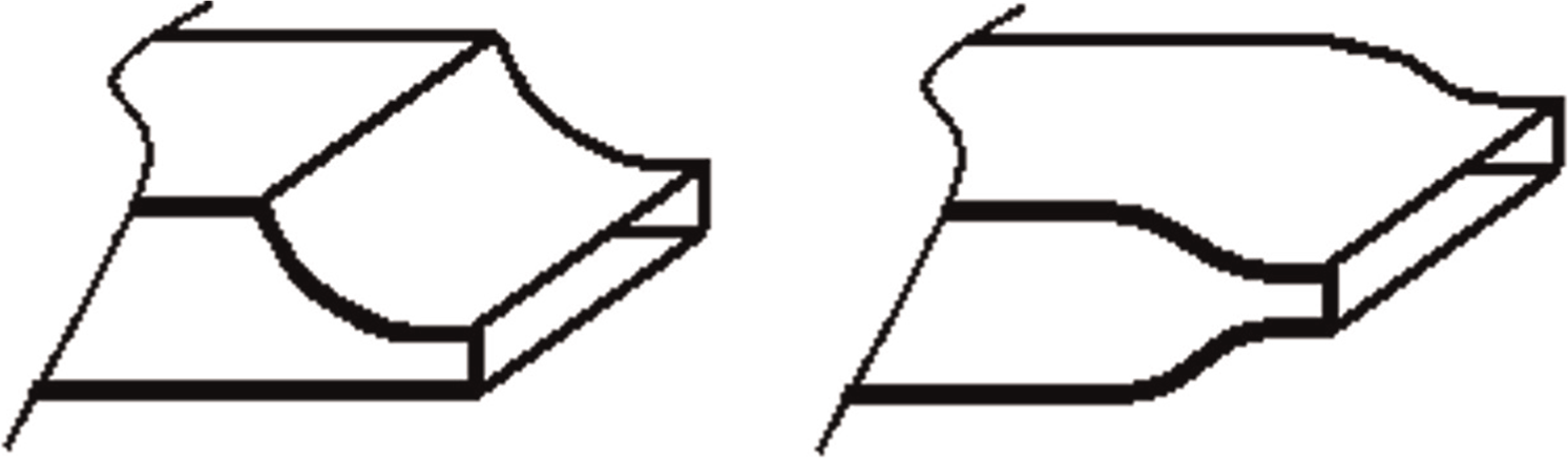
Two variations in a traditional rectangular flood-type nozzle.
Engineer et al. 10 have shown strong correlation between workpiece surface quality and the distance between the nozzle and the grinding zone such that a closer nozzle yields a higher finish quality. This phenomenon is understandable due to the rapid dispersion and aeration typical in cutting fluid jets; however, there may be physical constraints that make placement of the nozzle close to the workpiece impractical. Coherent jets, therefore, are an attractive alternative in many circumstances to try to increase the proportion of useful flow to applied flow by reducing the amount of air entrainment and dispersion of the jet. 6
The initial concept of applying a coherent fluid jet to machining originated in the 1950s with Rouse et al. 16 who had observed the jets created by fire-hose nozzles. The coherent jet nozzle was later designed and tested by McCarthy and Molloy, 17 who determined numerous characteristics that were necessary to create a high-quality coherent jet including: uniformly concave walls with a smooth surface, a smooth yet rapid transition from circular inlet to circular outlet, and a small length-to-diameter ratio. The ideal shape of the internal contours was not known at that point and is still under scrutiny with computerized flow simulations today. Although “pleasing to the eye” remains the rule of thumb, Figure 2 shows a current version of the coherent jet nozzle used by some industries, featuring inlet and exit diameters, length of curvature, and length of cylindrical exit region.
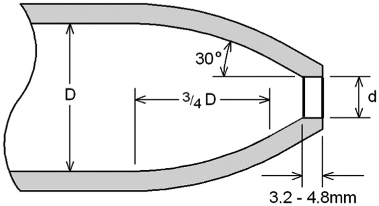
Suggested design parameters of “Rouse-type” coherent circular nozzle, including inlet and exit diameters (D, d).
A single circular exit from the nozzle is not the only shape that can create a coherent jet. Webster et al. 18 developed an improved rectangular nozzle with a rectangular aperture that utilized the converging concave geometry of the Rouse-type nozzle (see Figure 2) in the vertical plane. Research has also been conducted that suggests both coherency and high pressure are beneficial characteristics of cutting fluid jets. Steffen et al., 19 for example, reported that a round coherent jet could achieve an improvement in the critical specific material removal rate by 30%−60%. In addition, Warkentin et al. 4 experimentally tested a circular non-coherent flood jet, a circular coherent jet, and a high-pressure fan jet in application to profile creepfeed grinding. This research suggested that there may be a benefit to using both coherent jet nozzles and high-pressure nozzles. Unfortunately, the coherent jet and the high-pressure jet in this research used vastly different pressures and flow rates so it was impossible to conclude which nozzle geometry was superior.
Further research needs to be directed toward nozzle design for profile creepfeed grinding. Webster, 20 for example, points out that it is commonly believed in industry that the jet shape must match the profile shape—where expensive electrical discharge machining (EDM) processes are often used to try to create a nozzle orifice that exactly follows the profile shape. Webster 20 indicates that the internal nozzle geometry of such nozzles is not ideal and the complex orifice shape often causes the jet to break up and not deliver coolant where it is needed along the profile. Although Webster 20 created a multiple-orifice nozzle that yielded a series of parallel semi-coherent jets to try to overcome these issues, the multiple-orifice nozzle design is more bulky and complex to implement than a single-orifice nozzle. Furthermore, for a given coolant delivery system, increasing the number of orifices on a nozzle can lead to lower individual jet pressures, speeds, and flow rates when compared with a single-orifice nozzle.
Therefore, the goal of this research is to develop and test different-shaped single-orifice nozzles for profile creepfeed grinding that have the needed complex nozzle internal geometries to realize low-divergent jets over a wide range of jet pressures with little or no jet break up. A novel approach using rapid-prototyping is taken in this research to realize these complex nozzle internal geometries to eliminate the need for costly EDM. The performance of a rectangular nozzle (similar to Webster’s “Rouse-type” rectangular nozzle), a round coherent jet nozzle (similar to Figure 2), and an innovative oval coherent jet nozzle (hypothesized by the present authors to provide better coverage for the profile being ground) was investigated while keeping the grinding conditions the same for the different nozzles tested. In addition to the various nozzle aperture shapes tested, the workpiece feedrate and the jet pressure were varied to determine which parameter is most influential on the resulting workpiece quality.
Experimental method
The nozzles used in this research were fabricated through a process of fused deposition rapid prototype modeling using acrylonitrile butadiene styrene (ABS) plastic. This novel approach takes advantage of rapid prototyping’s ability to easily manufacture the complex internal nozzle geometries required to achieve a desired jet shape and coherency. An aluminum mounting block with a hollow core was first affixed to a Blohm Planomat 408 CNC creepfeed grinding machine as shown in Figure 3. The mounting block was developed to allow for the insertion of interchangeable “nozzle cores” containing the complex internal cavities of the nozzles being tested. These internal nozzle cavities were designed and modeled in AutoCAD and printed by a StrataSys Dimension BST 1200ES series modeler. Using this assembly, the nozzle bracket provided the necessary strength while the ABS nozzle core provided the necessary geometry.
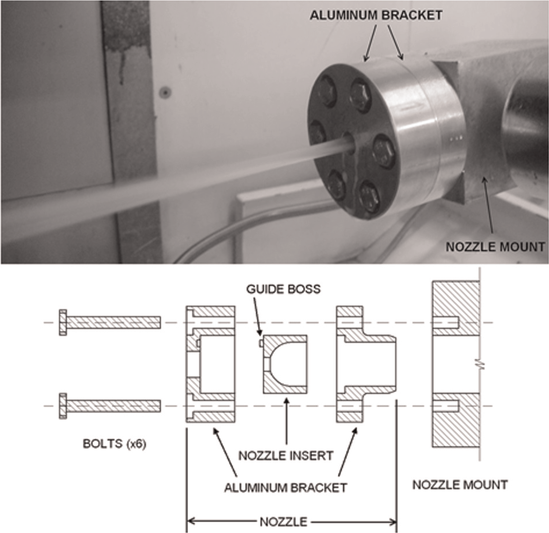
Nozzle assembly.
Because the nozzles used in this study were to be exclusively ABS plastic, feasibility testing was performed to verify that a rapid prototyped nozzle could not only produce an identical jet to a machined aluminum nozzle but also remain stable without showing any signs of wear in excess of 90 min of continuous use. To this end, a circular ABS nozzle was modeled to replicate the existing circular aluminum coherent nozzle. The ABS nozzle was then subjected to 90 min of continuous fluid flow at 37.9 LPM and digital images were periodically taken of the jet from which measurements of jet width could be obtained. Figure 4 presents the data from this testing in the form of measured jet width (at 200 mm downstream of the nozzle) plotted as a function of time, where the trend line represents the average jet width. The uncertainty plotted in Figure 4 represents a single standard deviation found between multiple width measurements at each measurement time. The very small slope of −2 × 10⁻⁵ mm/min indicates that little, if any, wear or breakdown of the rapid prototyped nozzle is occurring over the 90-minexperiment. Based on the promising findings of these preliminary tests, ABS nozzles with more complex internal contours were then used in the remainder of this work with confidence.
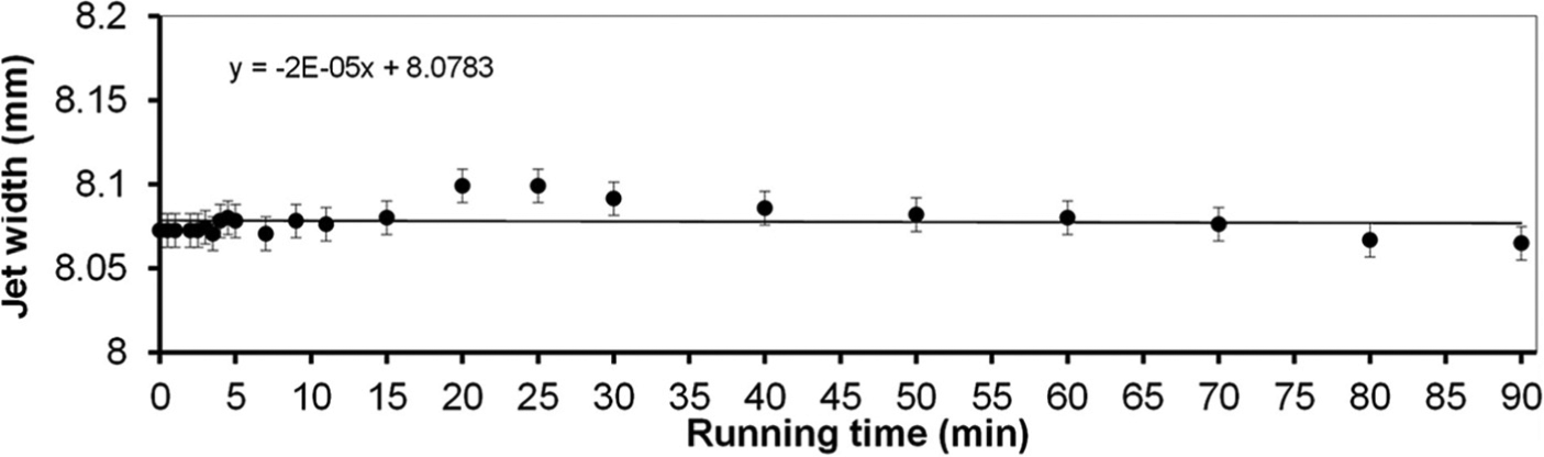
Jet width over time as produced by a rapid prototyped circular nozzle.
As shown in Figure 5, three different nozzle designs (rectangular, round coherent, and elliptical coherent) were tested in this research. This figure summarizes the aperture dimensions as well as the minor and major axis contours of each of the three nozzle designs: (a) circular, (b) elliptical, and (c) rectangular. Although the aperture shape was different for each nozzle, to ensure that the flow rate and fluid pressure were as consistent as possible across all tests, all nozzles had the same aperture cross-sectional area (9.62 mm2, equivalent to that of a circle 3.5 mm in diameter). These nozzle designs were selected in order to create a wide range of profile coverage and jet speeds. The geometry of the rectangular nozzle used in this research was based on the existing Webster design; that is, with the same smoothly converging geometric properties of a “Rouse-type” nozzle in the vertical plane as shown in Figure 2. The aperture was given an aspect ratio of 8.41 as a representative example of industry-standard wide-aperture general purpose nozzles. The design of the round coherent jet was based on the original design proposed by Rouse (Figure 2) and tested by Steffen et al. 19 for non-profile (flat) creepfeed grinding.
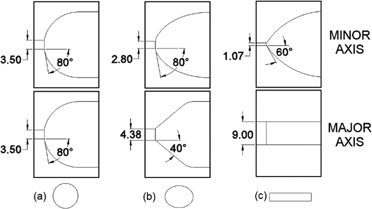
Nozzle contours and apertures used: (a) circular, (b) elliptical, and (c) rectangular.
The novel elliptical aperture nozzle, having an aperture ratio of 1.56, was developed and tested because it represents a compromise between the circular and rectangular aperture nozzles as it could combine the desirable characteristics of jet coherency of a round nozzle with the wider coverage of a rectangular nozzle. Typically, elliptical nozzles described in previous studies have had low jet coherence—with jet divergence angles in the range of 10°–15°, while the jet divergence angle of the optimized elliptical nozzle presented here is on the order of 1° using a combination of computer-aided design techniques and experimental testing. 21
For this elliptical nozzle, two nozzle aperture orientations were used: a horizontal nozzle orientation (where the major axis of the elliptical aperture on the nozzle was placed horizontally) and a vertical nozzle orientation (where the major axis of the elliptical aperture on the nozzle was oriented vertically). It was observed that the horizontal nozzle orientation produced an elliptically shaped jet as expected; however, the orientation of the major axis of this elliptical jet was, surprisingly, vertical. This switching of major and minor axes from the nozzle orifice to the jet is called axis switching and this phenomenon was also observed with the vertical nozzle (whereby the vertical nozzle’s elliptical jet exhibited a major axis aligned in the horizontal direction). As a result of axis switching, it is important in this article to keep in mind whether it is the nozzle orientation or the jet orientation being discussed (since, for example, the horizontal elliptical nozzle yields a vertical elliptical jet).
Profile creepfeed grinding experiments for this study were performed on a Blohm Planomat 408 CNC grinding machine using CimCool CimTech 310 recycling cutting fluid maintained at an ambient 19 °C. Fluid was circulated via a Giant P400A Series Triplex positive displacement plunger pump powered by a 575-V electric motor. The grinding wheel used was a vitrified aluminum oxide wheel from Radiac Abrasives, roll dressed by a profiled diamond wheel to impart the geometry shown in Figure 6 on a 1018 cold-rolled steel bar stock workpiece.
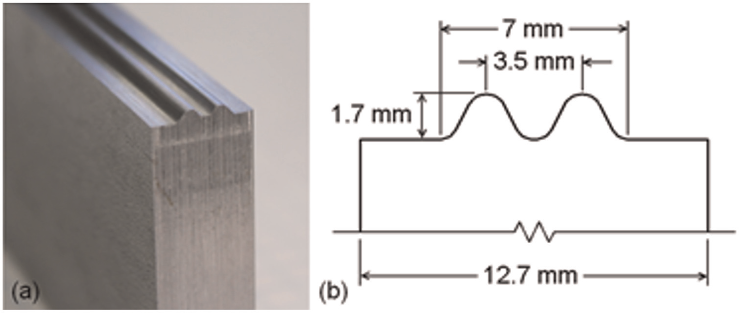
(a) Photograph and (b) schematic of profile imparted to workpiece.
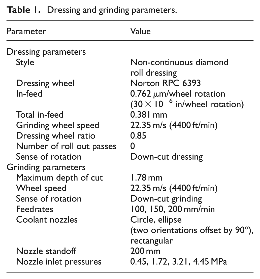
The parameters tested in this study include nozzle aperture shape, workpiece feedrate, and nozzle inlet pressure. Due to the nature of the profile geometry shown in Figure 6, the depth of cut varied across the 12.7-mm width of the workpiece from 0.078 mm at the peak to 1.778 mm on the flats. Table 1 summarizes the dressing and grinding parameters used. Testing three different feedrates (100, 150, and 200 mm/min) at four different nozzle inlet pressures (0.45, 1.72, 3.21, and 4.45 MPa) for each of the four different coherent jets (three different nozzles, with the elliptical nozzle having two different orientations offset by 90°) yielded a total of 48 experimental variations.
Dressing and grinding parameters.
For each grinding experiment, surface profile measurements as well as grinding wheel spindle power consumption were collected. Surface profile measurements were obtained with a Nanovea PS 50 chromatic confocal optical profilometer. Spindle power was monitored with a Load Controls PH-3A Power Cell Power Transducer. Immediately after each grinding experiment, the surface profile of each workpiece was measured at the following three locations along the workpiece surface: within 5 mm of full wheel engagement (30 mm along the workpiece), mid-grind (80 mm along the workpiece), and within 5 mm prior to loss of full wheel engagement (115 mm along the workpiece). These measurements were used to determine the workpiece profile error e across the 12.7-mm width of the workpiece as well as the workpiece surface roughness Ra at each of the three locations along the length of the workpiece. Workpiece profile error is defined by
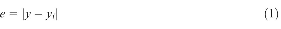
where y is the height of the desired profile and yi is the height of the measured profile. To quantify this profile error in terms of acceptable surface finish, workpiece surface roughness Ra is defined by
where n is the number of data points collected along the workpiece profile.
Experimental results
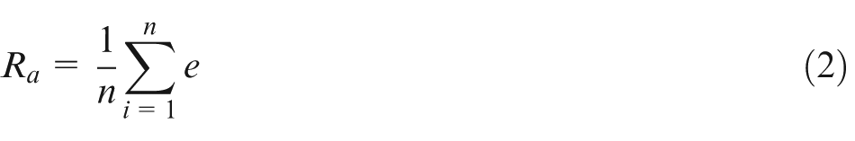
Nozzle performance was evaluated based on measurements of surface profiles and power. The workpiece profile error and roughness were used to help quantify the workpiece tolerance and finish. The power was used as a measure of grinding efficiency (such that a lower power indicates a more efficient process). Regions of large profile error, when viewed in conjunction with spindle power measurements, indicate locations where a failure occurred. Typical failures involve workpiece burn and wheel clogging followed by a phenomenon called wheel breakdown—that is, when bonds between abrasive grains or the grains themselves are damaged. Figures 7 and 8 present workpiece surface profiles, workpiece profile errors, workpiece surface roughness, and corresponding spindle power experimental measurements at 30, 80, and 115 mm along the workpiece for sample cases when wheel breakdown did not occur and when wheel breakdown did occur, respectively. The results shown in Figure 7 correspond to the vertical elliptical nozzle for a workpiece feedrate of 100 mm/min and a nozzle inlet pressure of 4.45 MPa, while the results shown in Figure 8 are from the rectangular nozzle for a workpiece feedrate of 150 mm/min and a nozzle inlet pressure of 0.45 MPa. In Figure 7(a)–(c), it can be seen that at 30, 80, and 115 mm along the workpiece length, respectively, the workpiece profiles are very similar and that the spindle power (Figure 7(d)) gradually increases as the grinding wheel traverses the length of the workpiece. This gradual increase in power is indicative of a decrease in grinding efficiency as the wheel wears, and the slight improvement in surface roughness Ra from 4.5 μm at 30 mm along the workpiece down to 4.0 μm at 115 mm along the workpiece suggests that the wheel likely became slightly smoother as wear flats were generated on the wheel surface. 22
Example of no wheel breakdown, vertical elliptical nozzle (horizontal elliptical jet), feedrate = 100 mm/min, and pressure = 4.45 MPa. Workpiece profiles at: (a) 30mm, (b) 80mm and (c) 115mm along the workpiece and (d) corresponding spindle power.
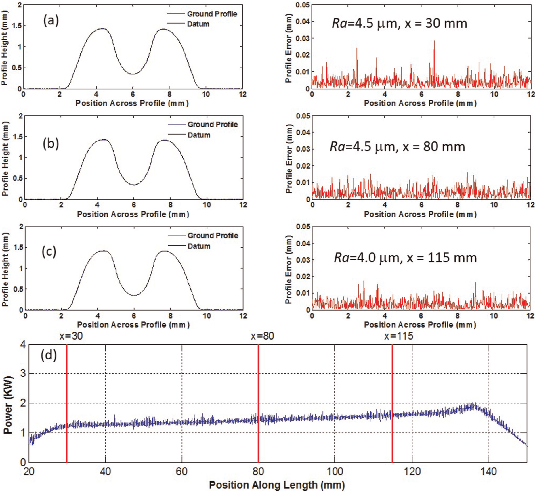
Example of wheel breakdown, traditional rectangular nozzle, feedrate = 150 mm/min, and pressure = 0.45 MPa. Workpiece profiles at: (a) 30mm, (b) 80mm, (c) 115mm along the workpiece and (d) corresponding spindle power.
Comparing Figures 7 and 8, it can be seen that when wheel breakdown occurs, the initial and final workpiece profiles change with profile errors becoming significant near the 2- and 10-mm locations across the profile. Furthermore, the workpiece surface roughness drastically increases from 5.7 μm at 30 mm along the workpiece (Figure 8(a)) up to 19.2 μm at 115 mm along the workpiece (Figure 8(c)). Figure 8(d) also clearly shows a sudden increase in spindle power when failure in the grinding process occurred, followed by a decrease in spindle power as the wheel continued to break down. Figure 8 also demonstrates why it is important to not only look at the surface roughness value Ra but also examine the profile error results when assessing the performance of a grinding experiment. Figure 8(c), for example, shows a significant increase in Ra compared with Figure 8(a) and (b). A single Ra value, however, does not provide all the information needed to understand the failure that is occurring. When examining the corresponding profile errors in Figure 8, for example, it becomes evident that a large Ra value is not due to a complete wheel failure across the entire width of the profile, but is rather due to localized wheel breakdown near the 2- and 10-mm locations across the profile—the profile errors themselves in Figure 8(a)–(c) are otherwise quite similar.
It should also be pointed out that, as seen in Figure 8, wheel breakdown occurred near the 2- and 10-mm locations across the profile. It is likely not a coincidence that these two locations across the profile where wheel breakdown occurs also correspond to the greatest grinding depth of cut and smallest radius of curvature across the profile. Because these two locations on the wheel profile provide the least amount of bond support for the abrasive grains, when coupled with large depths of cut, they are the first to fail.
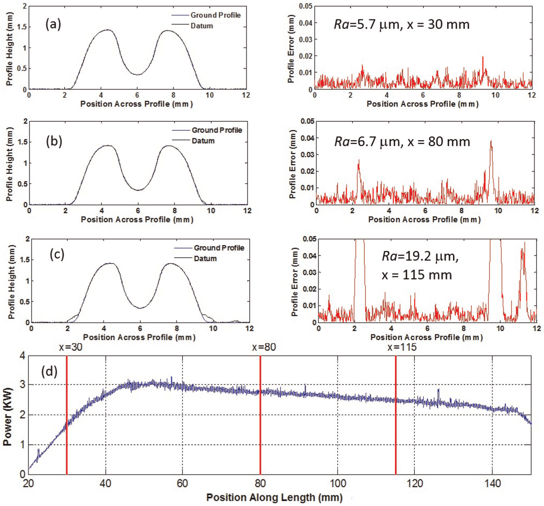
Keeping the feedrate and nozzle inlet pressure constant at 200 mm/min and 4.45 MPa, respectively, Figure 9 shows sample of the experimental results corresponding to the four different jets tested. The profile error and corresponding surface roughness values presented in this figure were measured at a point 80 mm along the length of the workpiece. It can be seen from these results that, for the grinding conditions presented, although no wheel breakdown occurred for any of the nozzles, different nozzle shapes can produce different results. For example, the circular nozzle (top row of Figure 9) performed the best with a surface roughness Ra of 3.7 μm, followed very closely by the horizontal elliptical nozzle (row 2 of Figure 9) with an Ra of 4.0 μm. Having an Ra of 4.7 μm, the vertical elliptical nozzle did not perform as well as the horizontal elliptical nozzle, while the rectangular nozzle (bottom row of Figure 9) performed worst with an Ra of 5.2 μm. The higher power measurements corresponding to the vertical elliptical and the rectangular nozzles also indicate that these nozzles result in grinding processes that are less efficient and are close to wheel breakdown.
Examples of four different jets; feedrate = 200 mm/min and pressure = 4.45 MPa.
Focusing on the vertical elliptical nozzle for a constant feedrate of 200 mm/min at 80 mm along the workpiece, Figure 10 shows sample results of how increasing the nozzle inlet pressure can improve the grinding process. Looking at the top row of Figure 10, it can be seen that relatively low nozzle inlet pressures of 0.45 MPa result in wheel breakdown exhibiting large profile error occurring near the 2- and 10-mm locations across the profile, an Ra of 14.1 μm, as well as a very prominent spike in the spindle power. As nozzle inlet pressure increases, however, it is clear that the profile error consistently decreases down to an Ra of 3.6 μm at a nozzle inlet pressure of 4.45 MPa. As the nozzle inlet pressure increases, Figure 10 shows that the spindle power also consistently decreases and no signs of wheel breakdown are observed. It is interesting to observe that although increases in nozzle inlet pressure appear to improve the grinding results, the amount of improvement becomes smaller at higher pressures. This observation suggests that there are diminishing returns in surface roughness and spindle power for an increase in pressure if one considers the excess coolant and pump wear at high pressures—a diminishing returns phenomenon very similar to what was observed by Steffen et al. 19
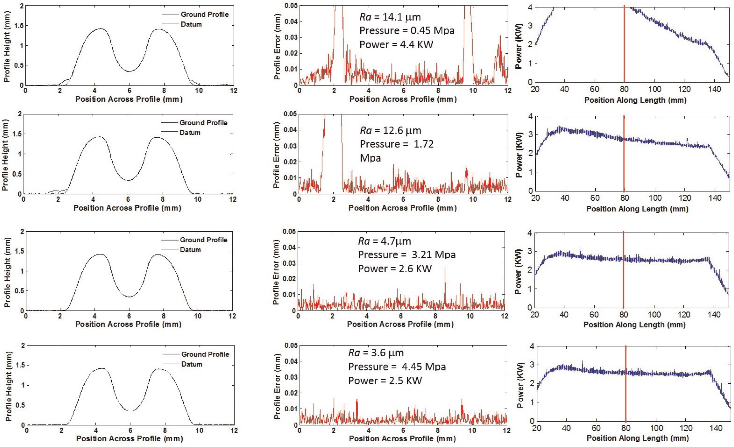
Vertical elliptical nozzle (horizontal elliptical jet) for different nozzle inlet pressures; feedrate = 200 mm/min.
Table 2 summarizes the results of all 48 different experiments carried out by showing which nozzles, feedrates and pressures led to wheel breakdown. This table was generated by examining the workpiece profiles, surface roughness and spindle power for all experiments conducted, and if wheel breakdown occurred, then the location of this failure along the length of the workpiece (30, 80, or 115 mm) was noted as “oox” if wheel breakdown occurred after 80 mm, “oxx” if wheel breakdown occurred after 30 mm, or “xxx” if wheel breakdown occurred at or before 30 mm. Key indicators of wheel breakdown include areas of high-profile error corresponding to large Ra values along with large deviations in power exceeding approximately 3 kW (for the conditions used in this research, 3 kW appears to be the grinding burn limit). Any portions of the table left blank indicate that no failure was observed for the grinding conditions being tested.
Summary of experimental results for each nozzle shape tested.
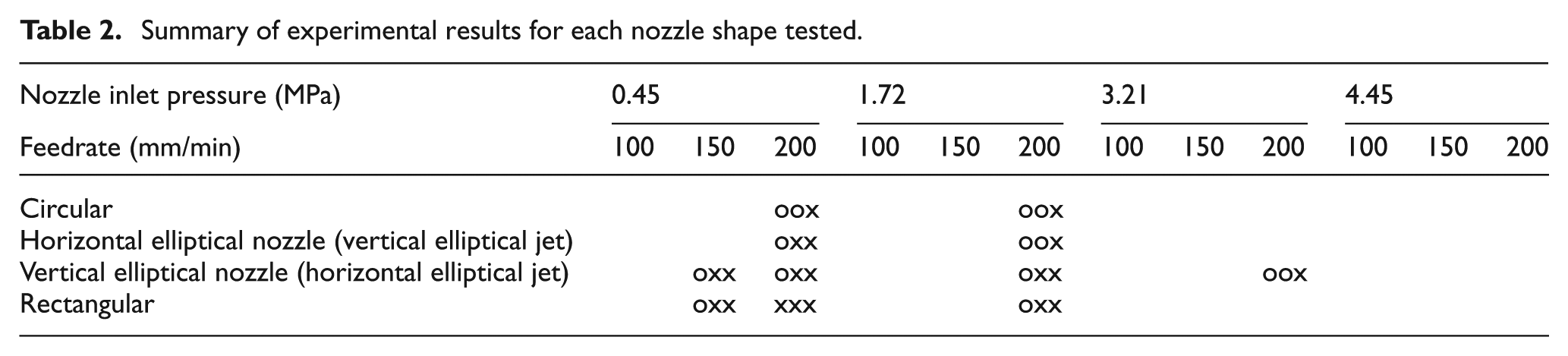
It can be seen from Table 2 that while all nozzles resulted in more breakdown at higher feedrates and lower nozzle inlet pressures, for the experimental conditions used in this research, the rectangular nozzle generally experienced the most wheel breakdown and, therefore, performed worst—closely followed by the vertical elliptical nozzle. The observed wheel breakdown for both the horizontal elliptical nozzle and the circular nozzle was very similar. Figure 11 summarizes (for all the feedrates and nozzles tested) the average surface roughness Ra and power as a function of nozzle inlet pressure for the non-breakdown cases. This figure clearly shows that the rectangular nozzle generally yielded the highest surface roughness and power when compared to the other nozzles. For the non-breakdown cases, the other three nozzles yielded very similar surface roughness and power results and, in general, surface finish improved with an increase in nozzle inlet pressure.
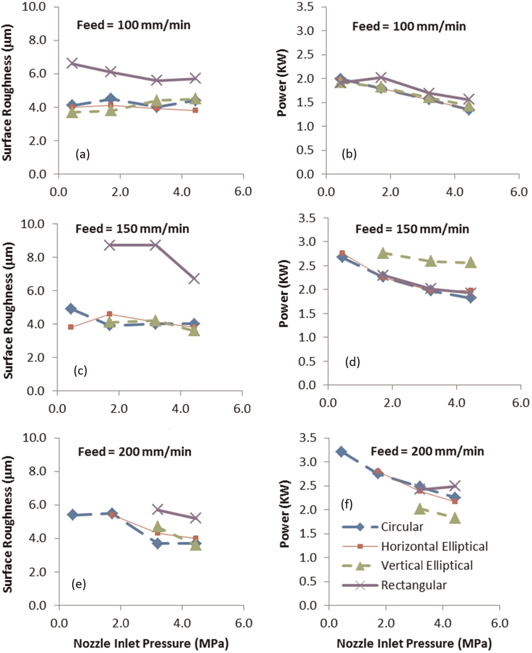
Surface roughness and power as a function of nozzle inlet pressure for non-breakdown cases. (a) Roughness: Feed=100mm/min, (b) Power: Feed=100mm/min, (c) Roughness: Feed=150mm/min, (d) Power: Feed=150mm/min, (e) Roughness: Feed=200mm/min and (f) Power: Feed=200mm/min.
Analysis and discussion
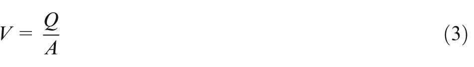
This section discusses how jet speed and jet coverage can help explain why the circular and horizontal elliptical nozzles generally performed the best in terms of having the fewest cases of wheel breakdown, followed by the vertical elliptical nozzles, and, finally, the rectangular nozzle. In order to quantify the jet characteristics, a digital image analysis method similar to that of St-Pierre et al. 23 was used to calculate the cross-sectional areas A of the jet at the location of the grinding zone 200 mm downstream of the nozzle. The horizontal and vertical widths of the jets were measured and it was assumed that the jets produced by both the elliptical and rectangular nozzles are elliptical in shape. The nozzle inlet pressure was maintained for all the nozzles by adjusting the speed of the positive displacement pumps (from which flow rate Q was derived). Assuming that the flow distribution in the jet is evenly distributed, then an estimate of the jet speed V can be calculated for each nozzle as a function of nozzle inlet pressure using the following equation
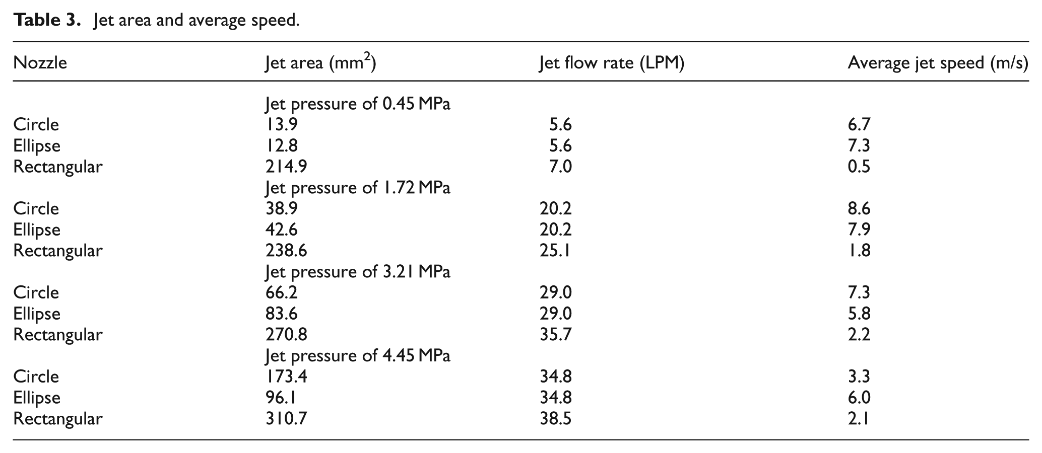
The corresponding jet areas, flow rates, and speeds for all the nozzles are summarized in Table 3. It can be seen from this table that the speed of the positive displacement pump (flow rate) was increased slightly for the rectangular nozzle in order to achieve the desired nozzle inlet pressure; however, this increase was within approximately 10% of the circular and elliptical nozzle flow rates.
Jet area and average speed.
The resulting jet speed is plotted in Figure 12 as a function of nozzle inlet pressure for the circular, elliptical, and rectangular jets. It is evident that while the jet speeds for the circular and elliptical nozzles are similar, the rectangular nozzle yields the lowest jet speeds for all pressures tested. Lower jet speeds result in less coolant being able to penetrate into the grinding wheel and, ultimately, the grinding zone—which helps explain why the rectangular jet performed poorest out of all nozzles tested in this research.
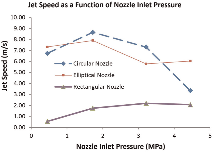
Approximate jet speeds for different nozzles tested.
To help explain why the circular and horizontal elliptical nozzles performed better than the others, Figure 13 visually shows the shape and coverage of each jet superimposed onto the workpiece and wheel profiles for the four different jets tested at the point at which the jet interacts with the grinding zone. It can be seen in this figure that, for each nozzle, the jet coverage is shown to increase with nozzle inlet pressure, while the shape and orientation of the nozzle are represented by the smallest solid shape (circle, rectangle, ellipse) at the center. In the case of the vertical elliptical nozzle, the jet is spread out over the width of the workpiece and, compared to the narrower coverage of the circular and horizontal elliptical nozzles, the authors hypothesize that there is greater chance for the coolant to slide and leak off to both sides of the profile (as the flow follows the path of least resistance), rather than flow toward the small-radii locations where it is needed most.
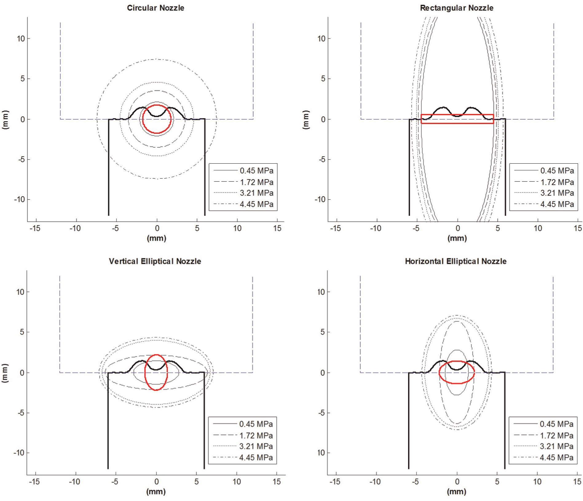
Resulting orientation and shape of jets tested.
Figure 13 can also be used to help explain why the results generally improved as nozzle inlet pressure increased. At low pressures, Figure 13 shows that the jet is not able to cover the entire width of the workpiece (regardless of the nozzle shape used). As nozzle inlet pressure increases, however, the jet coverage also increases which enables the coolant to cover more of the workpiece being ground and increases the lubrication and cooling in the grinding zone over the entire workpiece surface.
Conclusion
This research studied different nozzle aperture shapes including circular, elliptical, and rectangular over a range of workpiece feedrates and nozzle inlet pressures for the profile creepfeed grinding process. It was observed that, for the grinding conditions used in this research, the circular and horizontal elliptical nozzle shapes performed the best and the rectangular jet performed the worst. It was observed that as feedrate increased, the workpiece profile error, surface roughness, and spindle power generally increased and ultimately led to wheel breakdown—regardless of jet shape. It was also observed that as nozzle inlet pressure increased, the workpiece profile error, surface roughness, and spindle power generally decreased and fewer wheel failures occurred during the grinding process—again, regardless of jet shape. The reason that an increase in pressure generally improves the grinding results is likely related to the fact that at higher nozzle inlet pressures, the jet diverges and is able to better cover the full width of the workpiece. Furthermore, as pressure increases, the speed of the jet increases enabling coolant to better penetrate the grinding wheel and enter the grinding zone to provide better coolant and lubrication. Based on the results presented in this research, the ideal nozzle would be one that maximizes coverage of the entire profile while minimizing the chances of side leakage and is relatively inexpensive and easy to fabricate. For the grinding conditions used in this research, the circular nozzle did the best job of meeting all these requirements.
Footnotes
Acknowledgements
The authors would like to thank Mr Josh Latka, an undergraduate student in the Mechanical Engineering Department at Dalhousie University, for his work in streamlining the complex modeling process involved in generating the internal nozzle contours.
Declaration of conflicting interests
The author(s) declared no potential conflicts of interest with respect to the research, authorship, and/or publication of this article.
Funding
The author(s) disclosed receipt of the following financial support for the research, authorship, and/or publication of this article: The authors would like to thank the Natural Sciences and Engineering Research Council of Canada (NSERC) and the Canadian Foundation for Innovation (CFI) for their financial support of this research.