
Abstract
In order to efficiently remove heat from the machining zone, grinding fluids are used in the majority of grinding processes. Intensive cooling periods make it possible to efficiently influence the machining heat conditions, and through lubricating fluid components, limit the friction of active cutting vertices of unspecified geometry and a frequently negative rake angle. The obtained grinding results are considerably influenced by the amount of grinding fluid and the way it is delivered, which directly influences its effectiveness in reaching the zone of contact between the grinding wheel and the machined surface. The following article presents a new solution, as far as centrifugal grinding fluid delivery is concerned, through a special grinding wheel grip and the channels formed in it. Moreover, the system recommended here is also characterized by zonal grinding fluid delivery into the grinding wheel, which is aimed at additionally increasing the efficiency of grinding fluid delivery into the grinding zone. The results of tests evaluating the effect this system has upon grinding force values are presented. The reference methods employed in these tests were centrifugal grinding fluid delivery without zonal limitation, delivering grinding fluid using the flood method, as well as dry grinding. The results of the experiment showed that using the method recommended here enables the creation of conditions in the grinding zone similar to, or even more advantageous in certain conditions, than when delivering grinding fluid using the flood method. It also leads to a general reduction in grinding fluid expenditure by as much as 10 times.
Keywords
Introduction
The grinding process involves considerable temperature increase in the machining zone. The distribution of heat, which is created in deformed areas, is of an uneven nature, which contributes to increasing the heat stresses both in the grinding wheel and the workpiece. The major part of the energy used in the grinding process is transformed into heat, 75% of which is transmitted to the chips and 18% of which is transformed into heat in the area of contact between the tool and the chip. The remainder comprises either heat absorbed by the workpiece or the energy transformed into heat where the tool makes contact with the workpiece.1–3 In order to efficiently remove heat from the machining zone, grinding fluids (GFs) are used in most grinding processes. Intensive cooling makes it possible to exert effective influence on the machining heat conditions, while the lubricating fluid components limit the friction of the active cutting vertices of unspecified geometry and an often negative incidence angle.1,4,5
The basic tasks of the cooling liquids in the grinding process include1,4–6
The creation of a stable grease layer that limits friction between the abrasive grains and the machined object, as well as between the bond and the workpiece;
Cooling of the workpiece surface and the grinding wheel active surface (GWAS) through absorbing and removing heat;
Moistening the grinding wheel and cleaning the intergranular spaces of ground product;
Rinsing chips and other machining products (chipped abrasive grains and bond particles) out of the grinding zone;
Anticorrosive protection of the grinder and the machined material;
Counteracting bacteria growth, foam formation in fluids, and so on.
One factor which has a considerable influence upon the grinding results obtained is the amount of GF and the way it is delivered, which directly influences its effectiveness in reaching the zone of contact between the grinding wheel and the machined surface. Numerous GF delivery methods have been developed and are presented synthetically in Table 1.1,4–24 Moreover, the solutions known from the literature and industrial practice have been divided in Table 1 into three groups, also taking into consideration the less frequently used delivery of lubricant and antiadhesive substances (in a solid state) into the grinding zone.
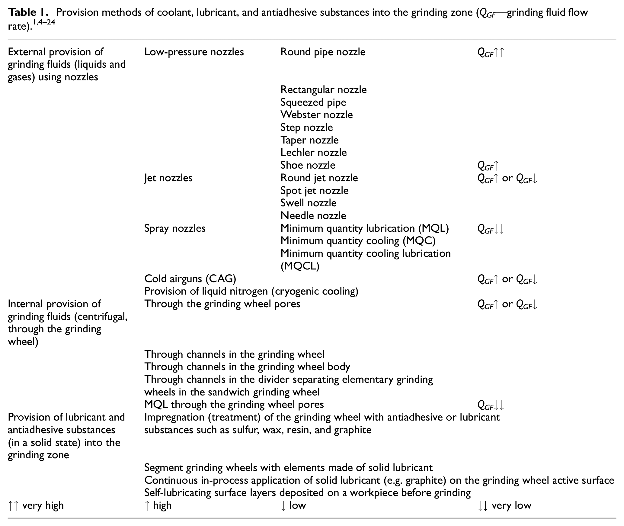
The most common methods include flood cooling, in which the GF is delivered under pressure using a pump and directed into the cutting zone through nozzles of varied geometry. As the area of contact between the workpiece and the grinding wheel increases, and the grinding wheel’s structural openness decreases, the intensity of GF delivery should rise. Moreover, GF delivery should also be greater where there are higher expectations concerning surface quality, the machining objects of complex shape or thin walls (in cases of hollowed-out items). In addition, in cases of cylindrical grinding and flat-surface grinding with the grinding wheel circumference, fluid consumption may be 8–10 L min−1, although a value 5 L min−1 is usually assumed. As far as centerless grinding is concerned, the GF consumption should be no greater than 3–6 L min−1 for each 10 mm of contact length. However, in the case of flat-surface frontal grinding, this value should range from 10 to 15 L min−1 for each 10 mm of grinding wheel or abrasive segment width. Such recommended highs of GF expenditure mainly result from the fact that in the flood method only 5%–30% of the GF actually reaches the grinding zone. 25
One factor which has a great influence upon the effectiveness GF operation, particularly in the form of a stream delivered into the grinding zone at a low speed, is the rotating air jet, whose source is the rotating grinding wheel. 7 This is the so-called airbag phenomenon which surrounds the grinding wheel along its circumference and, when the grinding wheel peripheral speed reaches vs = 20 m s−1, causes deflection and spraying out of the GF stream. Indeed, the airbag phenomenon is the main obstacle that hinders the GF from reaching the contact zone of the GWAS with the machined surface. The most common methods of preventing the negative influence of such phenomena include pressurized GF delivery which consists of delivering the coolant at a speed approximate to the grinding wheel’s peripheral speed, as well as the application of shoe nozzles that move the airbag away from the grinding wheel in the GF delivery area and deliver the GF centrifugally, through the tool.1,6,7
This article presents a new solution concerning centrifugal GF delivery through a special grinding wheel grip and the channels formed in it. The system recommend here is characterized by zonal GF delivery into the grinding wheel, which is aimed at additionally increasing the efficiency of the GF reaching the grinding zone. The article also presents the results of tests concerning the influence of the system recommended here upon the values of the normal and tangential components of the grinding force. Centrifugal GF delivery without zonal limitation, delivering the GF using the flood method, as well as dry grinding, were all used as points of reference in this research. Moreover, the experimental test results described in this article are part of a broader research project that concerns the comprehensive evaluation of the method recommended here, including in relation to its influence on the conditions of carrying out a given process (grinding force and workpiece temperature), the quality of the workpiece’s surface layer (machined surface roughness and stress condition in the surface layer 26 ), as well as grinding wheel wear (evaluation of the grinding wheel tool life and of the radial and edge wear parameters).
The grinding force corresponds to the resistance of the workpiece toward the grinding wheel during the grinding process and is directly connected with the energy processed during grinding. It is, therefore, an important indicator of the grindability of the machined material. It is also the sum of forces affecting all the abrasive grains that take part in the grinding process.1,4–6 The grinding force is usually expressed in the form of components (most often normal Fn and tangential Ft components) that describe the force vector in relevant projections. The value of the grinding force depends directly on the following: a cross section of a layer cut with an unidentified number of cutting blades within the grinding zone, the number of cutting blades that take part in the process, the setting of parameters for grinding, as well as the conditions of contact between the grinding wheel elements and the workpiece surface that are mainly as a direct result of the type, amount, and method of GF delivery.
Zonal centrifugal coolant delivery system
The zonal centrifugal GF delivery system developed here is different from the method known from the literature, namely, that of centrifugal GF delivery through channels in the grinding wheel, 27 chiefly because of the application of a mobile aperture 28 (Figure 1).
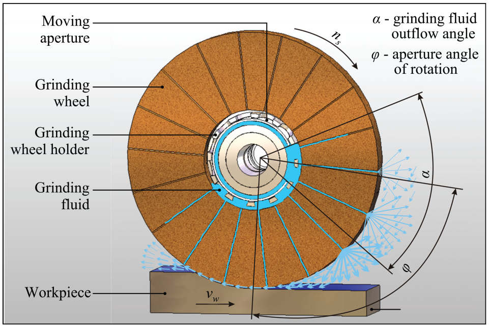
The goal of the aperture is to considerably limit the GF getting into all grinding wheel channels by directing the main fluid stream, with the proper angular advance, directly into the grinding zone. The anticipated result is a more precise and more effective GF stream directed solely into the targeted zone in a manner that is far more desirous as it considerably increases the amount of GF actually reaching the zone of contact between the grinding wheel and the workpiece.
The initial pilot tests carried out have confirmed the effectiveness of this new method of cooling and lubricating the grinding zone. The obtained test results, aimed at determining the possibility of limiting GF expenditure, show that the application of the described solution makes it possible to obtain the desired grinding process conditions (the forces and temperature were monitored), as well as having positive effects (both the machined surface roughness and stress condition of the surface layer were examined) even with an amount of GF as low as 0.5 L min−1. These initial tests also showed that the issue of possible grinding wheel imbalance, caused by zonal GF delivery into the tool, does not occur.
Methodology of experimental tests
Experimental setup
The experimental tests described were carried out using a stand with a type OC3-3711 flat-surface grinder. Overall views of the setup, along with the working zone and workpiece fixture with a type 9257BA Kistler dynamometer, are presented in Figure 2.
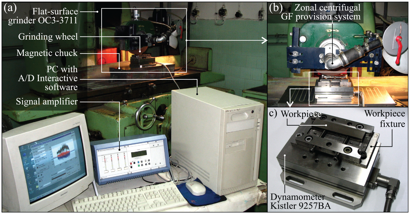
Experimental setup: (a) overall view, (b) working zone, and (c) workpiece fixture with dynamometer Kistler type 9257BA.
Grinding conditions
The focus of analysis in the described experimental tests of the reciprocal circumferential tangential surface grinding process was changes in the values of the registered grinding force components (Fn and Ft) when using various methods of GF delivery into the sample zone. Centrifugal GF delivery (without aperture)—Figure 3(b) and the flood cooling (Figure 3(c)), as well as dry grinding methods, were used as reference methods for the above-described zonal centrifugal GF delivery system (Figure 3(a)). Indeed, it needs to be stressed that in the case of centrifugal cooling methods (Figure 3(a) and (b)), the GF flow rate was QGF = 0.5 L min−1, while in the case of the flood method (Figure 3(c)) it was 10 times greater at QGF = 5.0 L min−1.
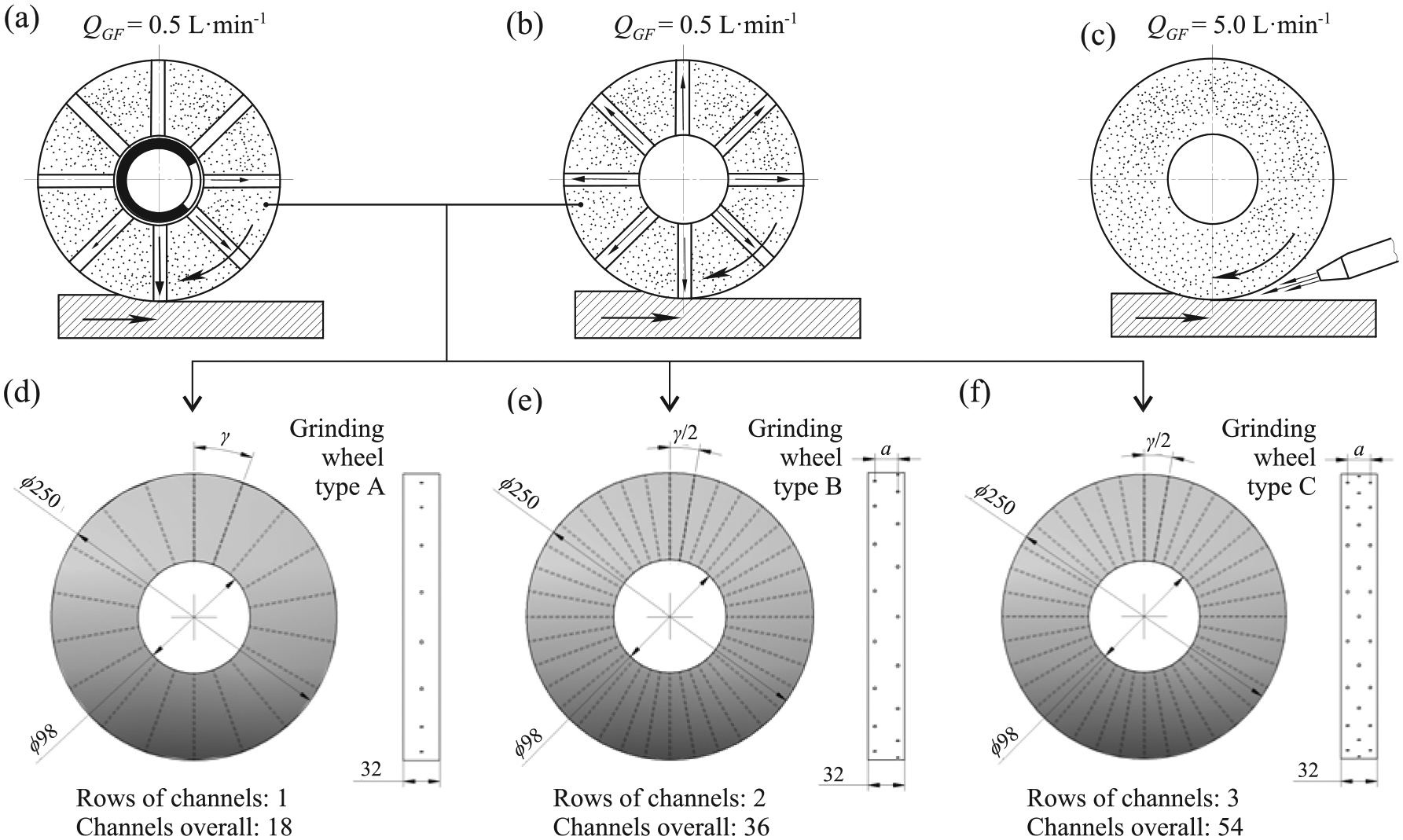
Cooling methods used in described experimental study (a)–(c) and design diagrams of the grinding wheels with channels providing GF to the grinding zone: (a) zonal centrifugal GF provision system, (b) centrifugal GF provision system without using aperture (reference method), (c) flood method (reference method), (d) grinding wheel type A, (e) grinding wheel type B, and (f) grinding wheel type C (a—distance between rows of channels in grinding wheel, γ—angle between rows of channels in grinding wheel).
In order to determine the influence that the different numbers and orientations of channels shaped in the grinding wheel had upon the delivery of the GF, specifically, as well as the course of the grinding process more generally, three grinding wheel construction variants were used in the tests outlined. These are presented in Figure 3(d)–(f). The first grinding wheel type (type A) was characterized by a single row of 18 holes, whose inlets were located in the center of the cylinder that constituted the grinding wheel (Figure 3(d)). Two rows (36 holes in total) were formed in grinding wheel type B and were located in proximity to the tool’s outer edge (Figure 3(e)). The greatest number of GF provision holes, namely, 54, was located in grinding wheel type C, in which there were three rows of holes, both on the edges and in the center of the GWAS (Figure 3(f)).
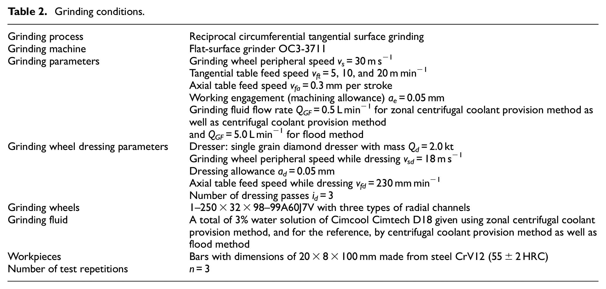
In addition, the value of the tangential table feed speed (vft = 5, 10, and 20 m min−1) was changed during the tests. The grinding wheel was dressed before each change of parameters or configuration in the grinding setup (wheel type and GF delivery method) in order to obtain a repeatable state of the GWAS. A complete presentation of the conditions of the completed tests is displayed in Table 2.
Grinding conditions.
Workpiece material
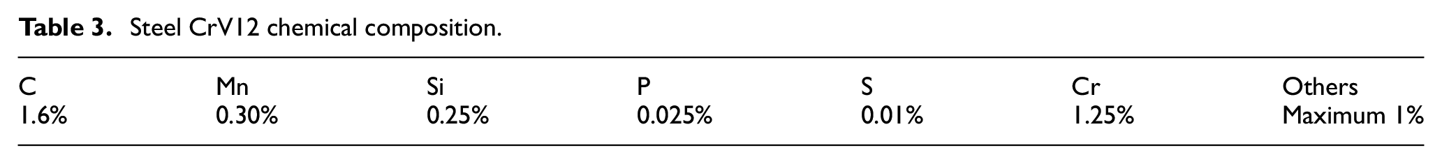
The workpieces were made in the form of parallelograms sized 100 × 20 × 8 mm, from CrV12 tool steel (Table 3). The workpieces were quenched in oil after preheating to 990 °C and were then tempered at 300 °C. The second stage of thermal treatment (tempering) was used to obtain a minimal stress condition in the surface layer of the workpieces. The sample hardness after heat machining was 55 ± 2 HRC.
Steel CrV12 chemical composition.
Grinding force measurement
The track for conducting grinding force measurement included a type 9257B piezoelectric force gauge by Kistler, upon which the sample was mounted using a special grip (Figure 2(c)). Another important element was a Kistler 5019A charge amplifier, which was conjugated with the force gauge using an analog–digital converter located on a DAS-1601 card. The last element of the measurement track was a computer equipped with dedicated software for the acquisition and analysis of the registered measurement data (Figure 2(a)).
The measurement results included in this article were determined as the arithmetic mean of three measurements carried out under the same conditions. The normal Fn and tangential Ft components of the grinding force were registered for three values of the tangential table feed speed, namely, νft = 5, 10, and 20 m min−1. Values of the grinding force components were registered with a frequency of f = 2.0 kHz per channel.
Results and discussion
The grinding force measurement results obtained are presented in the grinding time function found in the charts of Figures 4 and 5. Figure 4 presents changes in the normal grinding force component values over time, with changeable tangential table feed speeds of vfr = 5 m min−1 (Figure 4(a)), vfr = 10 m min−1 (Figure 4(b)), and vfr = 20 m min−1 (Figure 4(c)). Figure 5 presents charts illustrating changes in the tangential grinding force component values Ft.
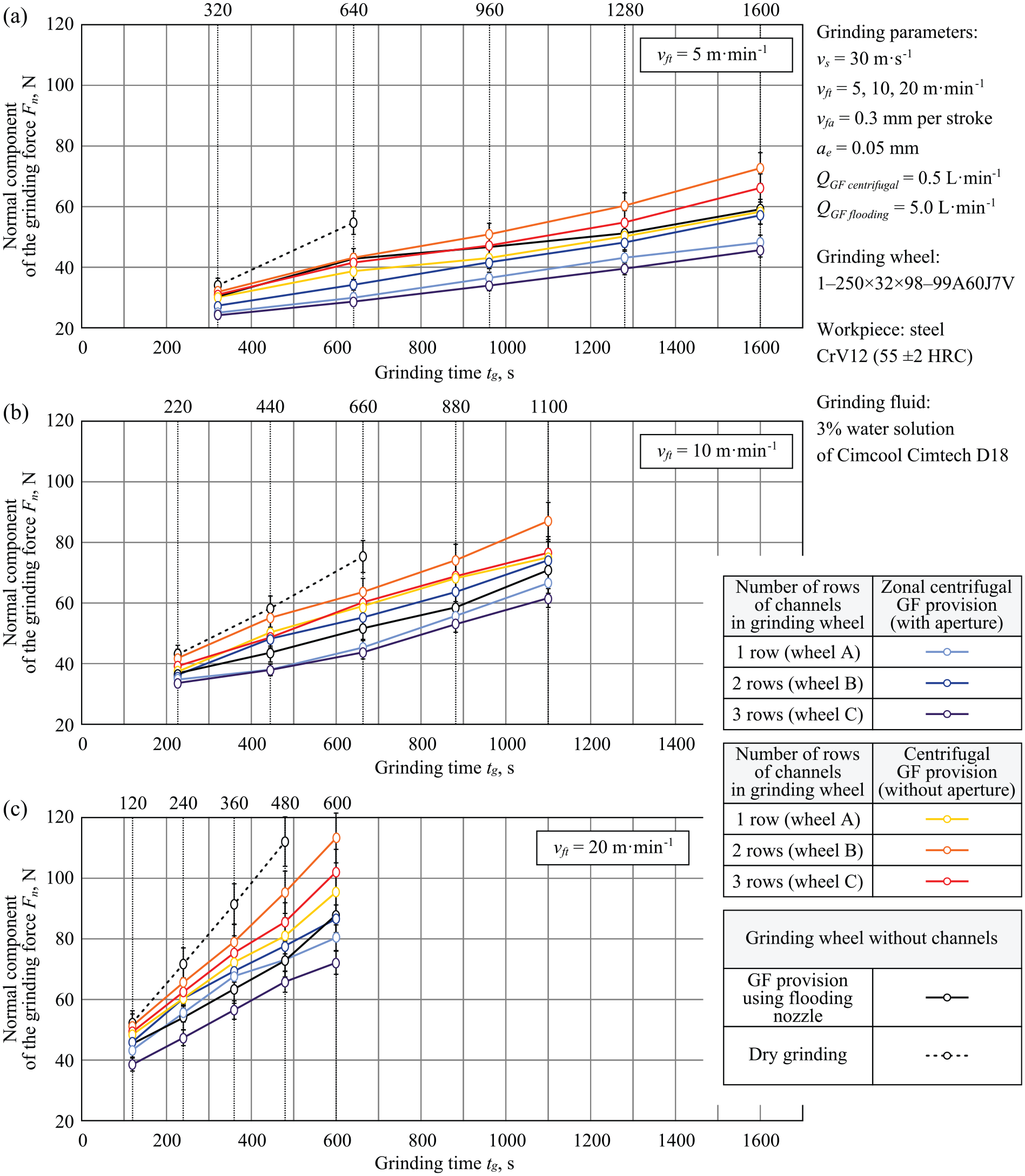
Values of normal components of the grinding force Fn recorded in the experimental tests for the analyzed GF provision methods: (a) vfr = 5 m min−1, (b) vfr = 10 m min−1, and (c) vfr = 20 m min−1.
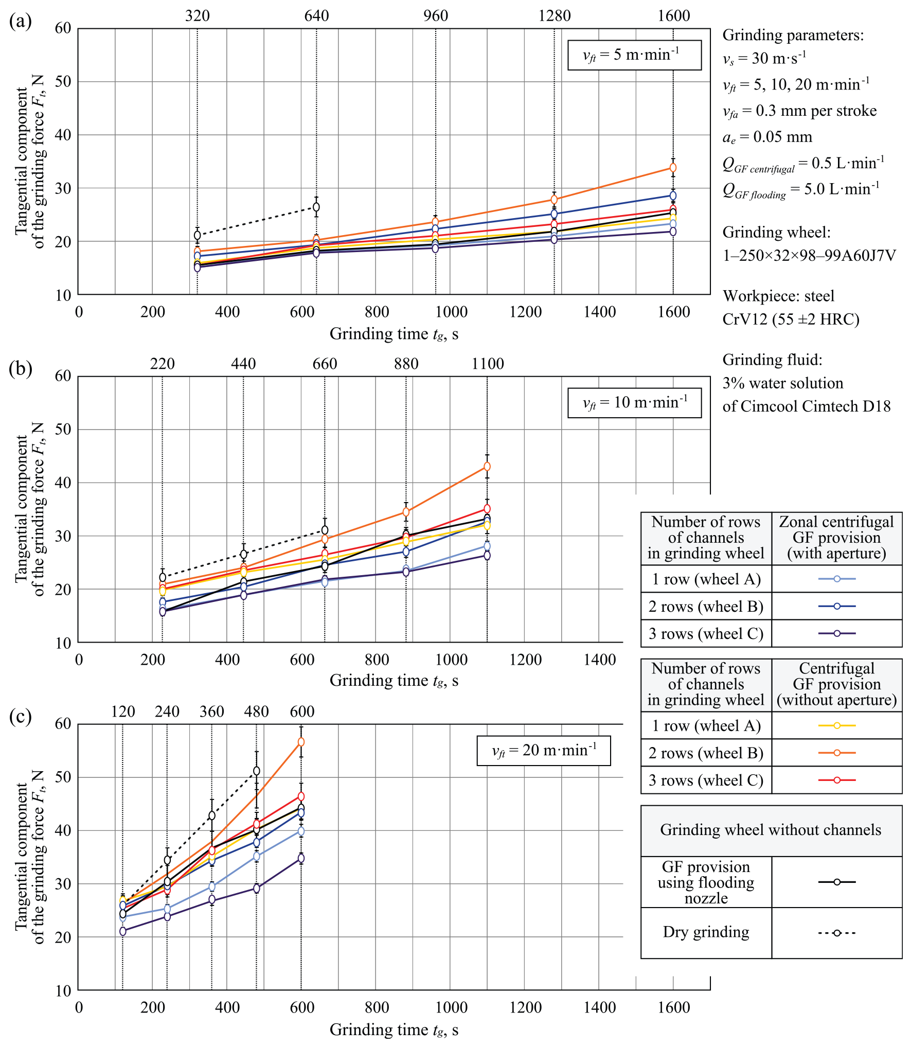
Values of tangential components of the grinding force Ft recorded in the experimental tests for the analyzed GF provision methods: (a) vfr = 5 m min−1, (b) vfr = 10 m min−1, and (c) vfr = 20 m min−1.
The registered values of the grinding force components Fn and Ft increased over grinding time tg, which is a result of the progressive wear of GWAS components. The greatest influence on the grinding forces obtained was exerted by the vft parameter value, whose increase considerably reduced the tool life (Figures 3 and 4).
When comparing the grinding force components’ values obtained during grinding using various methods of GF delivery into the grinding zone and without cooling, it may be observed that a lack of GF had an extremely negative influence on the grinding force. Moreover, in the final phase of the tests, grinding burns were observed on the workpiece surface in this case. Indeed, the considerable values of the grinding force components measured were as a result, in this case at least, of a lack of lubricant, meaning the friction force in the grinding zone greatly increased. At the same time, the lack of a cooling function (as no GF was delivered) caused premature heat wear of the abrasive grains’ active apexes, leading to their quick glazing, which further contributed to the creation of heat defects on the workpiece surface.
When comparing the grinding force values registered for the machining process carried out using the GF, it was observed that a 10-fold decrease of GF expenditure in the case of centrifugal cooling (both zonal and without an aperture) did not have a negative influence on the registered process parameters. However, the values obtained for the grinding force components were really only approximations in the cases of grinding with limited GF expenditure and grinding using the flood method (Figures 3 and 4). It should be observed that increasing the machining efficiency that resulted from increasing the tangential table feed speed vft led to the differences in particular GF delivery methods becoming visible (Figures 4(c) and 5(c)). In order to better illustrate these differences, Figure 6 shows the maximum values for normal (Fn) and tangential (Ft) components of the grinding force recorded in the experimental tests for the analyzed GF delivery methods and for the three levels of the vft parameter values.
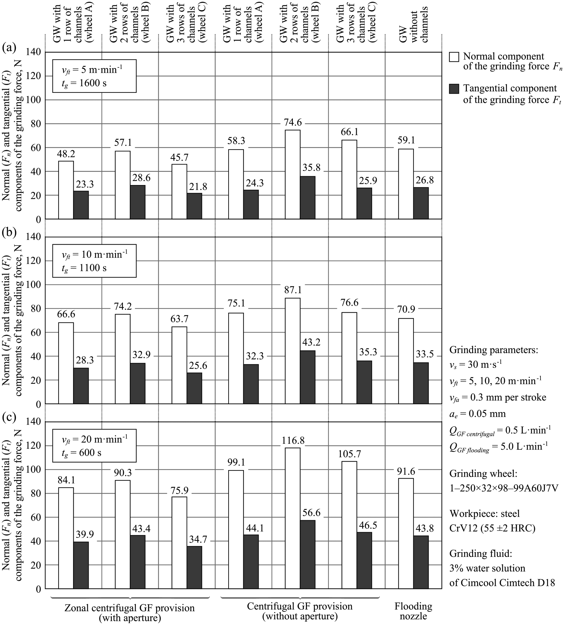
Maximum values of normal (Fn) and tangential (Ft) components of the grinding force recorded in the experimental tests for the analyzed GF provision methods: (a) vfr = 5 m min−1 and tg = 1600 s, (b) vfr = 10 m min−1 and tg = 1100 s, and (c) vfr = 20 m min−1 and tg = 600 s (GW—grinding wheel).
Analysis of the comparison presented in Figure 6 indicates that use of the aperture that guided the GF, and applied with very small GF expenditure, directly into the grinding wheel zone of contact with the workpiece makes it possible to obtain more advantageous grinding force components than in the case of centrifugal GF delivery without the aperture. The presence of a relatively intense GF stream in the area of contact between the grinding wheel and the machined material was obtained using a zonal centrifugal GF delivery system, which makes it possible to limit the abrasive, fracture, and adhesive wear of the grinding wheel. In addition, it visibly reduces the grinding force components’ values and slows their rise as the grinding time increases.
When using the zonal centrifugal GF delivery system combined with the grinding wheel characterized by three rows of holes, Fn and Ft component values were obtained that were lower than when using the flood cooling method with 10 times greater GF expenditure. This is indicative of a considerable increase in the level of the useful application of the delivered GF, particularly in the case of the zonal method. The application of three rows of channels delivering the GF into the grinding zone shaped in the grinding wheel (grinding wheel type C—Figure 3(f)) provides an even distribution of the GF directly into the vicinity of the area of contact between the active cutting vertices of the abrasive grains and the machined surface along the whole GWAS width. The results of the grinding force components’ values obtained in cases of employing grinding wheels with one (grinding wheel type A—Figure 3(d)) and two rows of channels (grinding wheel type B—Figure 3(e)), illustrated in Figures 4–6, indicate that these solutions are less advantageous. It needs to be stressed, however, that the registered differences in Fn and Ft values are often minor and do not undo the application potential of these solutions.
Conclusion
The results of the experimental tests carried out, the aim of which was to establish the influence of applying a new zonal centrifugal GF delivery system to the normal Fn and tangential Ft grinding force components in the process of reciprocal circumferential tangential surface grinding of steel CrV12, proved that the method recommended here possesses a high degree of effectiveness. Indeed, the registered values of the measured parameters indicate that it is possible to obtain conditions in the grinding zone which are comparable, and in some cases, even better than the flood method. Moreover, at the same time, it needs to be remembered that GF expenditure was reduced 10-fold, which contributes directly to the reduction of production costs connected with the purchase, regeneration, and disposal of these environmentally dangerous fluids.
The most important conclusions to be drawn from the analyses of the above-described experimental tests are as follows:
The crucial influence of GF delivery on the values of the examined grinding force components was proven, while the highest values were registered in the case of dry grinding;
The obtained grinding force components’ values for centrifugal GF delivery into the grinding zone were comparable to the results obtained when using the flood method, despite a 10-fold reduction in GF expenditure;
An influence regarding the number of channels delivering the GF into the grinding zone shaped in the grinding wheel was observed on the measured grinding process values. From among the grinding wheel structure types included in this research, the most favorable results were obtained for grinding wheel type C (three rows of channels), whose application allowed for an even delivery of the GF along the whole width of the GWAS in the grinding zone;
The research results showed a clear influence of the tangential table feed speed vft on the grinding force values and the grinding wheel tool life, which was as a result of increasing the grinding machining allowance as the vft value grew.
Footnotes
Appendix 1
Declaration of Conflicting Interests
The author(s) declared no potential conflicts of interest with respect to the research, authorship, and/or publication of this article.
Funding
The author(s) received no financial support for the research, authorship, and/or publication of this article.