
Abstract
The profile accuracy of screw rotor affects the performance of screw compressor directly. In precision form grinding, installation errors of grinding wheel are the crucial factors affecting profile accuracy of screw rotors. A numerical method for quantifying profile error of screw rotor was proposed to evaluate effects of installation errors of grinding wheel on rotor profile. Coordinate transformation and engagement theory were applied to generate rotor profile, and the error model of rotor profile was established by comparing the generated rotor profile with the original one. Furthermore, the error evaluation procedure was presented based on the discrete rotor profile points. Three kinds of installation errors of grinding wheel are analyzed including installation angle error, center distance error and axial position error in the numerical cases. By inputting installation errors of grinding wheel, the effects on rotor profile are evaluated considering both single-factor installation errors and coupled-factor installation errors of grinding wheel. The evaluated results provide a theoretical basis for error tracking and error compensation in screw rotor grinding. Grinding experiments were performed for female rotor with different installation errors. The experimental results verify the correctness of the evaluated results.
Introduction
Screw rotors are core parts in screw compressors as well as screw pumps. Profile accuracy of screw rotors affects the performance of screw compressor directly. 1 Accordingly, rotor profile requires an accurate manufacturing method for optimum performance. 2 To improve machining accuracy, the precision form grinding or form milling technology 3 is used to machine screw rotors. Park et al. 2 investigated a machining method by utilizing formed tools based on the feature of rotor shape for improving machining accuracy of asymmetric rotors.
Most of the researches have concentrated on machine tool accuracy for improving profile accuracy of screw rotors. Shen et al. 4 analyzed the error sources of machine tool as external errors and internal errors, and provided a novel method of error tracing and compensation on the basis of the limited sample trials, which effectively reduced the machined errors of rotor profile due to machine tool errors. Tian et al. 5 presented a general and systematic approach for geometric error modeling of machine tools, which enabled the source errors affecting position and orientation accuracy of the machine tool to be explicitly separated. In order to understand the relationship between grinding motion and the machined screw rotor surface, grinding process simulation has been studied. Wu and Fan 6 established a general coordinate system for the screw rotor form grinding and connected it to a vertical five-axis computerized numerical control form grinder to simulate the affection produced by the error curves of the grinder feed motion on the machined rotor geometry. Furthermore, Guo 7 reported that the influence of machine tool motion errors on rotor profile depends on the offset angle. In other words, the same machine tool motion accuracy under different offset angles will lead to different rotor profile error. Therefore, he concentrated on the selection of the offset angle to reduce the influence of process errors on the rotor profile.
The grinding wheel is also an important factor affecting the profile accuracy of the machined screw rotor. The researches on profile design of tool have been widely carried out. Wei and Zhang 8 developed a mathematical model on how to design the axial profiles of the cubic boron nitride (CBN) grinding wheel for precision grinding of screw rotors based on gear engagement theory. Tang et al. 9 proposed a new design method (form-position geometric method (FPGM)) for forming cutters on the basis of acquiring cutter tooth profile by meshing principle and spline interpolation method. This method avoided the solution to the derivatives at each discrete point when solving the equation of contact line by gear meshing theory and solved the accurate design problem of the cutter at the cusp of the screw tooth profile curve. Wu et al. 10 proposed a numerical radial-ray shooting method to instinctively generate the tool profile, the corresponding machine settings and the ground tooth profile. Shen et al. 11 presented a digital graphic scanning (DGS) method, based on computer scanning graphics, to generate the profile of grinding wheel, which can avoid the difficulties appeared from the complex nonlinear equations of the contact line by analytical gearing envelope method. Chen et al. 12 introduced an image-based method for examining the profile accuracy of grinding wheels used for micro-drill fluting, which was also suitable for screw rotor grinding. Tool wear always occurs during the machining of screw rotors. Stosic 13 presented a geometric approach to calculate tool wear in screw rotor machining. The envelope theory of gearing has been applied here as a meshing requirement for crossed helical gears to calculate the stock distribution, which would result in the uniform wear of a finishing tool. These studies mainly focused on the influence of profile design of grinding wheel and tool wear on the profile accuracy of the machined screw rotor, and little attention was paid to tool installation condition.
Grinding wheel installation has significant effect on grinding precision. Wang et al. 14 established an error analysis model of face gear grinding for reducing the face gear tooth profile errors induced by installation errors. For screw rotor grinding, Guo and Tang15,16 reported effective tool installation conditions should be used as the design criteria for the rotor tooth profile. Furthermore, the influence of manufacturing process variation on rotor profile considering setup conditions was analyzed. Stosic and colleagues17,18 presented a reverse tool to rotor transformation to evaluate the influence of the tool set errors on the machined screw rotor. It was also proved that a tool to rotor transformation procedure was useful to determine the effect of tool setting errors upon machined screw rotor profiles.
However, the errors of rotor profile were analyzed by geometrically qualitative comparison between the original rotor profile and the machined rotor profile in these studies, and the specific method for quantifying the errors of rotor profile has not been provided. Furthermore, to reduce tooth profile errors of screw rotors induced by mounting errors of CBN wheel, Wei et al. 19 established a mathematical model of the error analysis, and the influence curves of the profile errors affected by mounting errors and radius error of grinding wheel were obtained. However, this error model was limited to the situation that the number of data points of the machined rotor profile should equal to that of the original rotor profile, and the influence of coupled errors on rotor profile has not been studied.
The objective of the article was to propose a numerical method to evaluate the effects of installation errors of grinding wheel on rotor profile. First, the rotor profile generation model is introduced based on coordinate transformation and engagement theory. And then, by comparing the original rotor profile with the machined one, the error model of rotor profile can be established and the corresponding error evaluation procedure will be presented. The numerical cases for installation angle error, center distance error and axial position error of grinding wheel are used to verify the proposed method. The evaluated effects on rotor profile contribute to error tracking and error compensation caused by installation errors of grinding wheel in screw rotor grinding. And grinding experiments for female rotor with installation errors were performed by SK7032 grinder to verify the theory analysis of error.
Rotor profile generation model
In order to evaluate the effects of installation errors of grinding wheel on rotor profile, rotor profile generation model is required to be established by grinding wheel to screw rotor coordinate transformation and engagement theory.
As with the movement of screw rotor grinding, the rotor rotates around its axis; the grinding wheel rotates around its own axis at a high speed and moves along the axis of screw rotor at a constant speed. When the rotor rotates a circle, the grinding wheel moves a lead. For conveniently establishing rotor profile generation model, the relative movements between the grinding wheel and rotor are assumed that the grinding wheel is stationary, and the rotor rotates around its own axis and simultaneously moves along its axis with lead P. The coordinate systems for defining the rotor and grinding wheel geometry are given in Figure 1.
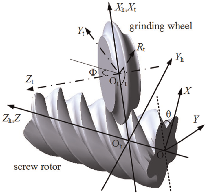
Rotor and grinding wheel coordinate systems.
In Figure 1, the moving coordinate system XOY, which rotates together with the rotor and moves along the Z-axis, and the coordinates
Given coordinates of grinding wheel profile,
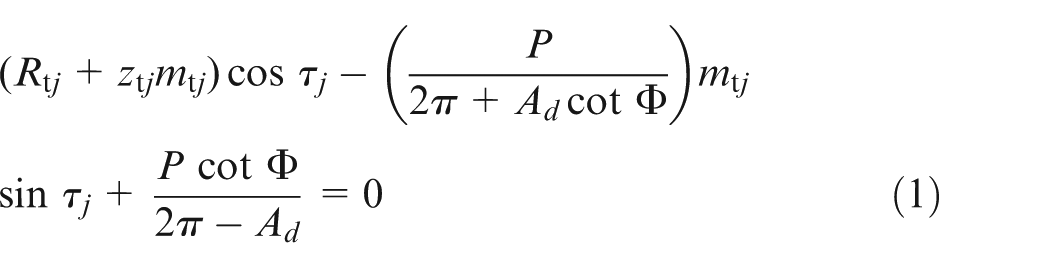
where
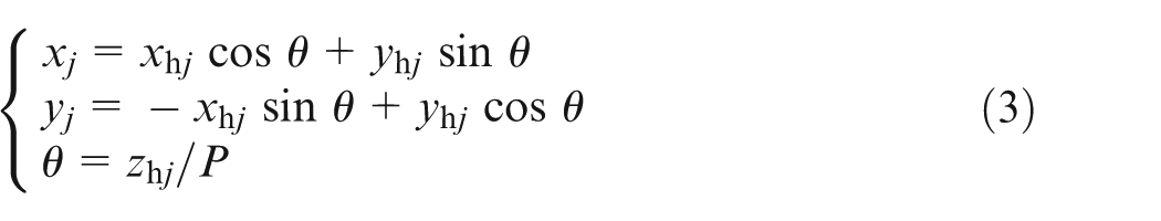
When
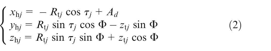
The transverse coordinates
Error model of rotor profile
Error calculation method of rotor profile
Rotor profile errors can be obtained by comparing the machined rotor profile with the original rotor profile. The preprocessing of rotor profile was needed for this comparison as shown in Figure 2. In XOY coordinate system, the origin point is selected as the reference point. Both the center of the machined rotor profile and the original one should be moved to the reference point for comparison. Meanwhile, the root radius of the machined rotor profile and the original one are required to rotate to the same contrast position which is parallel to Y-axis as shown in Figure 2.
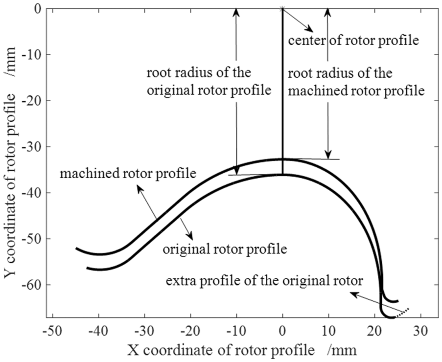
Preprocessing of rotor profile for comparison.
If the original profile and the machined profile cannot be aligned on the ends, as shown in Figure 2, the extra profile of the original rotor should be rotated with the divide angle
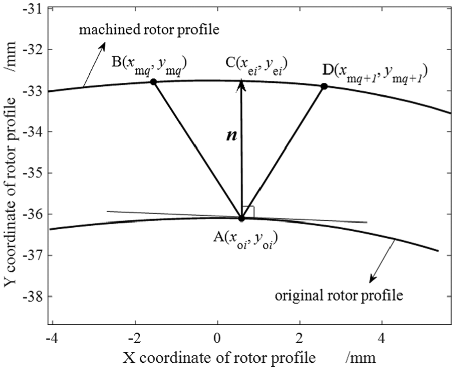
Schematic diagram of normal error calculation for point A.
The coordinates of point A are denoted by

where
Supposing that point C is the intersection point between the machined rotor profile and the normal vector of point A,
Since points B and D were the discrete points of the machined rotor profile, the machined rotor profile between points B and point D can be fitted by cubic parameter splines. The fitted rotor profile between points B and D was formulated as follows
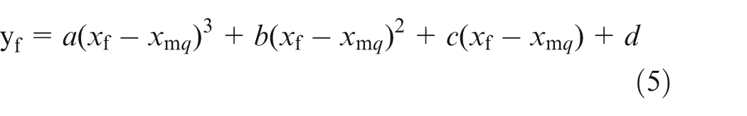
where a, b, c and d are the coefficient of the fitted curve, which are dependent on the coordinates of points B and D.
Based on equations (4) and (5), the coordinates of the intersection point C
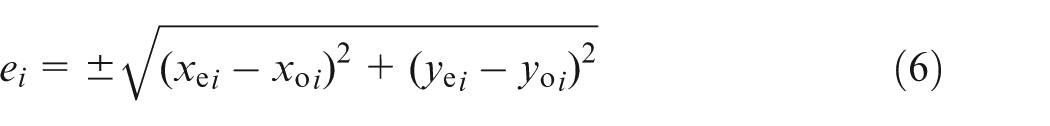
where if
To clearly observe the normal profile error of rotor, the coefficient
Furthermore, based on the normal profile error

Point interval search for the intersection point
The intersection point through which the normal vector of the original profile point passes is located in a unique point interval of the machined rotor profile. Therefore, the point interval should be determined for the coordinate calculation of intersection point first. For example, in Figure 3, the determination of point interval was to obtain the coordinates of points B and D, which were the necessary parameters for coordinate calculation of intersection point C.
If the rotor profile can be conveniently obtained from three-dimensional coordinate measuring instrument, the number of data points for the machined rotor profile may not equal the original one. Thus, isometric interpolation was used to solve this problem. By the cubic parameter spline function with equal interval
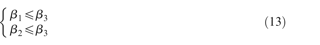
In order to shorten search time of point interval, the points of original rotor profile were divided into three kinds of region for point interval search of the intersection point according to angle
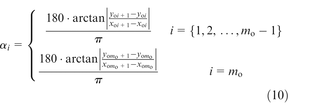
Note that for equation (10), if
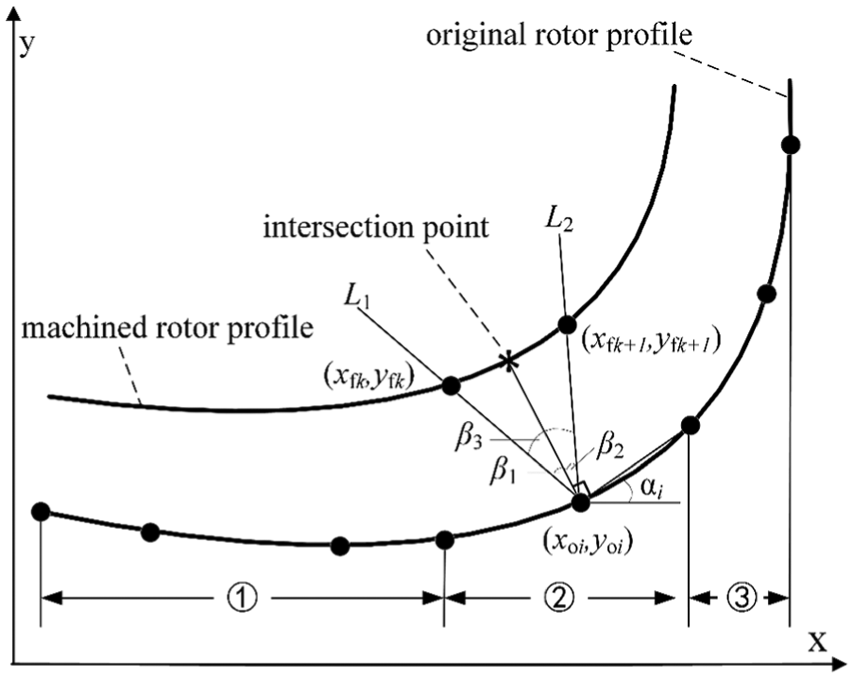
Point region for point interval search of the intersection point.
As shown in Figure 4, threshold for the angle
In region ① (

In region ③ (

In region ② (
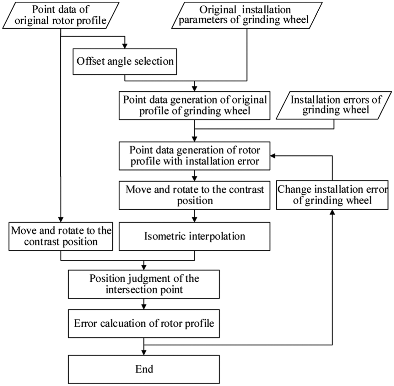
Error evaluation procedure of rotor profile.
Error evaluation procedure
The main procedure for error evaluation was presented in Figure 5. First, point data of original rotor profile with offset angle selection and original installation parameters of grinding wheel were input to generate point data of original profile of grinding wheel. In order to obtain the machined rotor profile with installation errors, the rotor profile model presented in section “Rotor profile generation model” was then used to combine the installation errors of grinding wheel with original profile of grinding wheel.
Subsequently, for the comparison between the original rotor profile and the machined rotor profile, the contrast position should be specified by moving and rotating both of them based on the preprocessing method in section “Error calculation method of rotor profile.” According to section “Point interval search for the intersection point,” in the situation of unequal numbers of data points for the two rotor profiles, isometric interpolation was used to interpolate the machined rotor profile by the cubic parameter spline function with equal interval. And then, formulas (11)–(13) were applied to judge the position of the intersection point by point interval search. When the position of the intersection point was obtained, the errors of rotor profile can be evaluated based on equations (6)–(9). The evaluated errors included normal errors of profile, average normal profile error, maximum normal profile error, minimum normal profile error and difference between maximum error and minimum error. If necessary, installation errors of grinding wheel can be varied to evaluate rotor profile errors in the evaluation procedure.
Numerical cases
In the numerical cases, a couple of intermeshing screw rotors was used to validate the error evaluation method. The design parameters of rotors are listed in Table 1.
Design parameters of rotors.
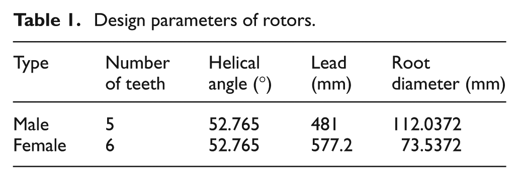
The outer diameters of grinding wheels for machining the male and female rotors are designed as 500 mm. Three kinds of installation errors of grinding wheel were considered including installation angle error
Effects of single-factor installation errors of grinding wheel on rotor profile
Effects of installation angle error
on rotor profile
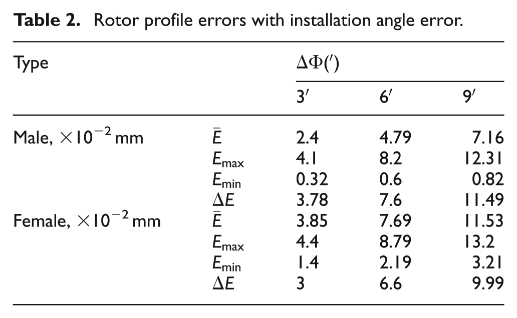
Three different installation angle errors of grinding wheel were considered as listed in Table 2, namely,
Rotor profile errors with installation angle error.
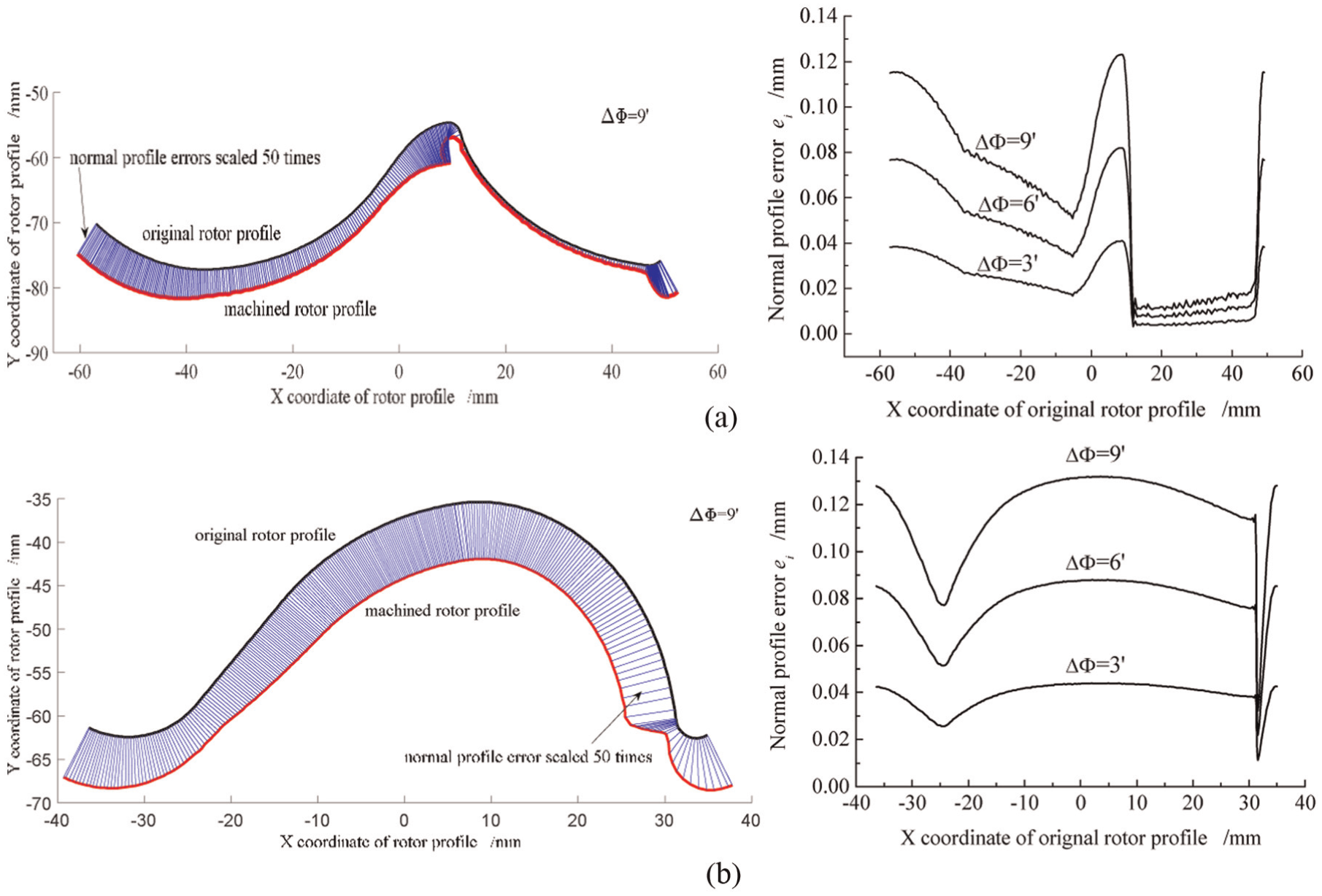
Effects of installation angle error on rotor profile: (a) male rotor and (b) female rotor.
As shown in Figure 6 and Table 2, both the male rotor profile and the female one are enlarged with the increment of installation angle. The increased amplitude of normal profile error is proportional to that of installation angle error. The effect of installation angle error on the male rotor profile is more significant than that on the female rotor profile.
Effects of center distance error
on rotor profile
The center distance between grinding wheel and rotor equals the sum of grinding wheel outer radius and rotor root radius. Due to wear of grinding wheel in rotor machining, center distance
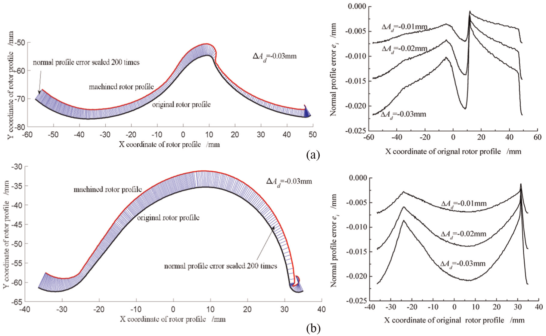
Effects of center distance error on rotor profile: (a) male rotor and (b) female rotor.
Rotor profile errors with center distance errors.
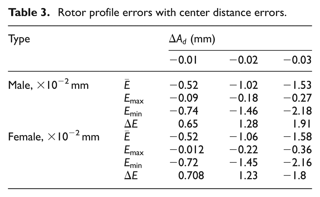
As illustrated in Figure 7 and Table 3, both the male rotor profile and the female one are smaller with the decrement of center distance. The reduced amplitude of normal profile error is proportional to the reduced amplitude of center distance error. The effect degree of center distance error on the male rotor is the same as that of the female rotor.
Effects of axial position error
on rotor profile
Considering three axial position errors of 2, 4 and 6 mm as input parameters, the machined rotor profile with axial position error was obtained as shown in Figure 8. Comparing the original rotor profile with the machined one introducing axial position error in Figure 8, the deflection angle between the two rotor profiles can be obviously observed. Therefore, when introducing axial position error, deflection angle
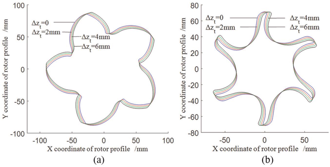
Effects of axial position error on rotor profile: (a) male rotor and (b) female rotor.
Rotor profile error with axial position error.
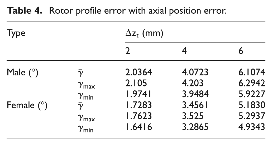
As shown in Figure 8 and Table 4, when the axial position of grinding wheel is increased, the rotor profile rotates clockwise with a deflection angle
Effects of coupled-factor errors with installation angle error
and center distance error
on rotor profile
According to the analyzed effects on rotor profile for single-factor installation error evaluation of grinding wheel in section “Effects of single-factor installation errors of grinding wheel on rotor profile,” both installation angle error
Cases of installation angle error and center distance error for evaluating effects.
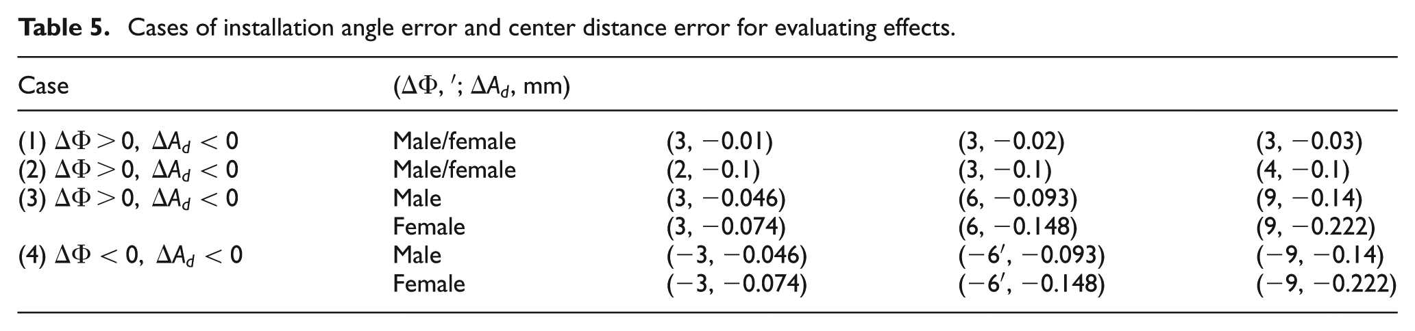
Effects on rotor profile for case (1)
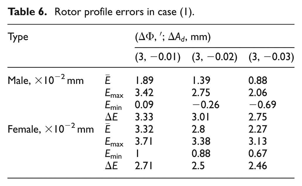
Taking case (1) in Table 5 as imported parameters, the effects on rotor profile were obtained as shown in Figure 9, and the calculated rotor profile errors with the coupled-factor errors were presented in Table 6. In Figure 9, it is observed that the machined rotor profile and its normal profile error curves with coupled-factor errors are similar to the ones with single-factor error of installation angle in Figure 6. It indicates that installation angle error is the dominant factor affecting normal profile error of male rotor and female rotor in case (1). And also, in Table 6, the decrement of the center distance results in the reduction of the average normal profile error as well as the difference between the maximum error and minimum error.
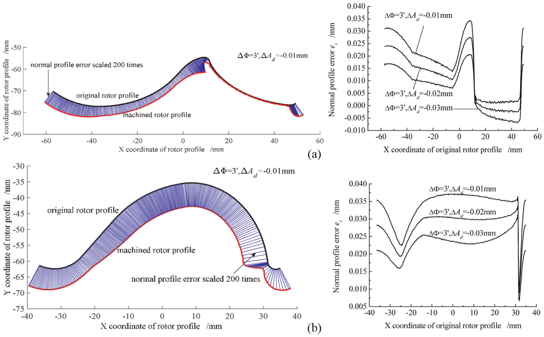
Effects of installation angle error and center distance error on rotor profile in case (1): (a) male rotor and (b) female rotor.
Rotor profile errors in case (1).
The coupling effects on normal profile error for the installation angle error and the center distance error were further evaluated as shown in Figure 10. In Figure 10(a), the curve
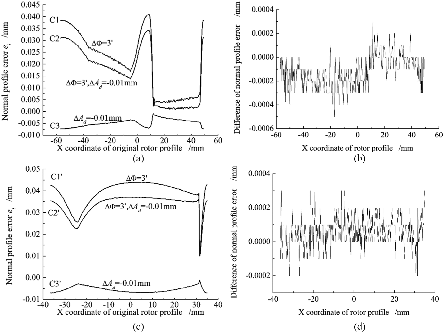
Coupling effects on normal profile error of rotor in case (1): (a) male rotor, (b) male rotor, (c) female rotor and (d) female rotor.
Effects on rotor profile for case (2)
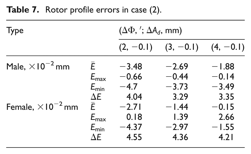
For case (2), Figure 11 depicts the effects on rotor profile with the coupled-factor errors. Table 7 presents the rotor profile errors with the coupled-factor errors. Similar to case (1), comparing Figure 12 with Figure 7, it can be seen that the dominant factor affecting normal profile error of male rotor and female rotor was the center distance error in case (2). According to Table 7, the average normal profile error as well as the difference between the maximum error and minimum error is decreased with the increment of the installation angle.
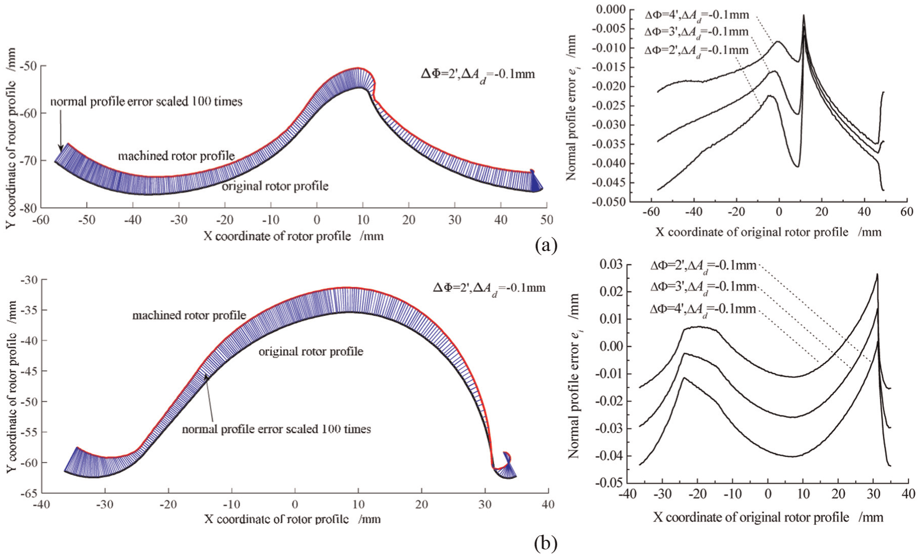
Effects of installation angle error and center distance error on rotor profile in case (2): (a) male rotor and (b) female rotor.
Rotor profile errors in case (2).
Coupling effects on normal profile error of rotor in case (2): (a) male rotor, (b) male rotor, (c) female rotor and (d) female rotor.
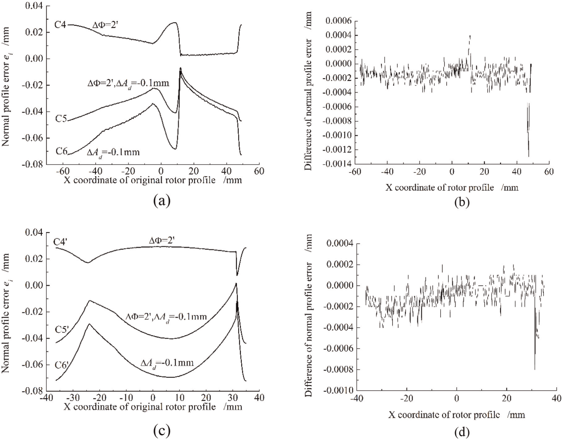
Figure 12 shows the coupling effects on normal profile error for case (2). Similarly, for normal profile errors of the male rotor in Figure 12(a), the curve
Effects on rotor profile for case (3)
For case (3) with the varied values of the two coupled factors, the effects on rotor profile were presented in Figure 13. As shown in Figure 13, the normal profile error curve with the coupled-factor errors was different from the one with single-factor error for installation angle in Figure 6 as well as for center distance in Figure 7. It indicated that both of the two coupled factors have effects on normal profile error of rotor in case (3). For the male rotor in Figure 13(a), after introducing the coupled-factor errors (
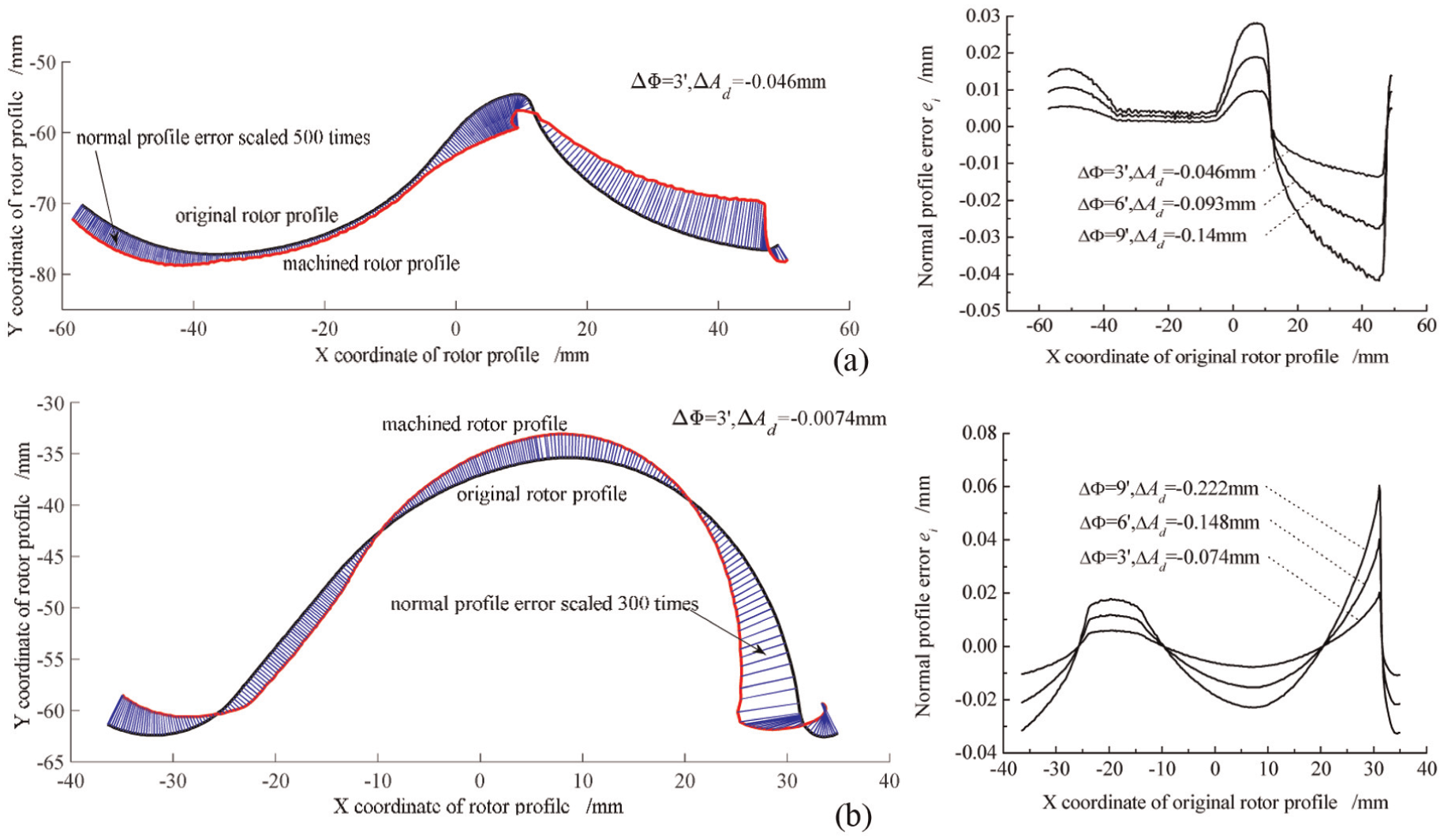
Effects of installation angle error and center distance error on rotor profile in case (3): (a) male rotor and (b) female rotor.
Table 8 provides the calculated rotor profile errors with the coupled-factor errors for case (3). It can be seen that with the increment of the installation angle and the decrement of the center distance, the difference between the maximum normal profile error and minimum normal profile error
Rotor profile errors in case (3).
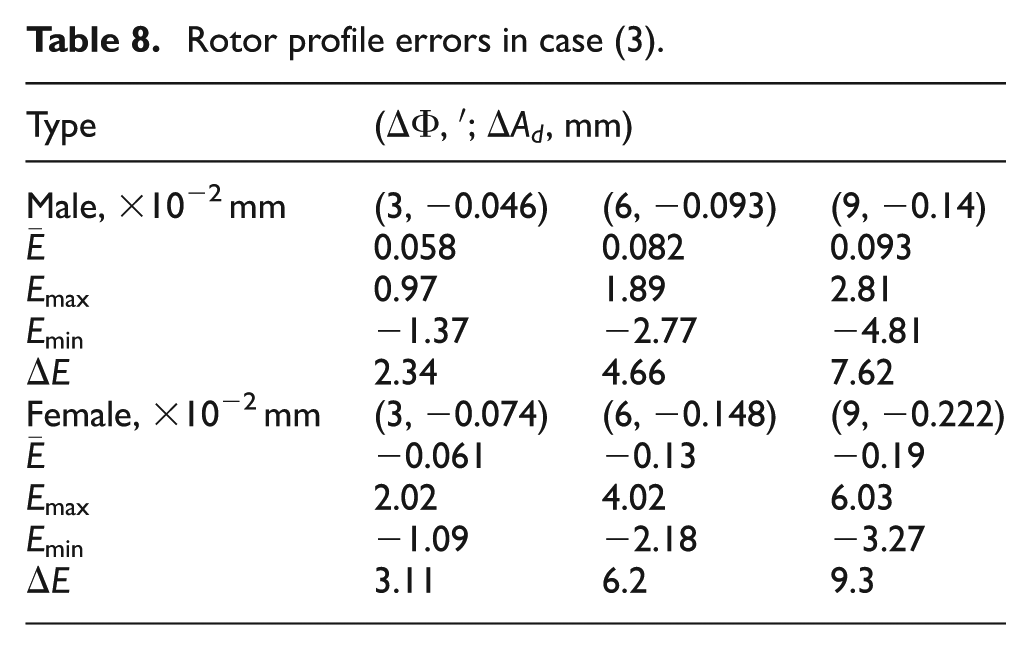
Figure 14 presents the coupling effects on normal profile error for case (3). The linearly superposition effects on normal profile error of rotor for the coupled-factor errors were also observed for both male rotor and female rotor, as shown in Figure 14(a) and (b) for male rotor and Figure 14(c) and (d) for female rotor. For example, the difference between the curve
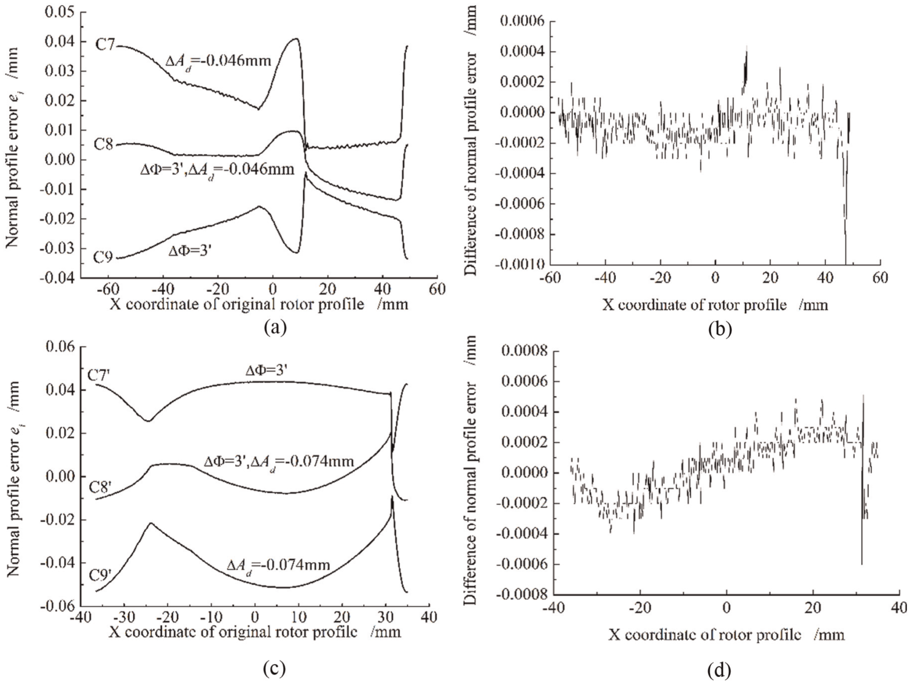
Coupling effects on normal profile error of rotor in case (3): (a) male rotor, (b) male rotor, (c) female rotor and (d) female rotor.
Effects on rotor profile for case (4)
For case (4), Figure 15 shows the effects on rotor profile with the coupled-factor errors of grinding wheel. The shrinkage effects on the machined rotor profile are observed caused by both installation angle error and center distance error.
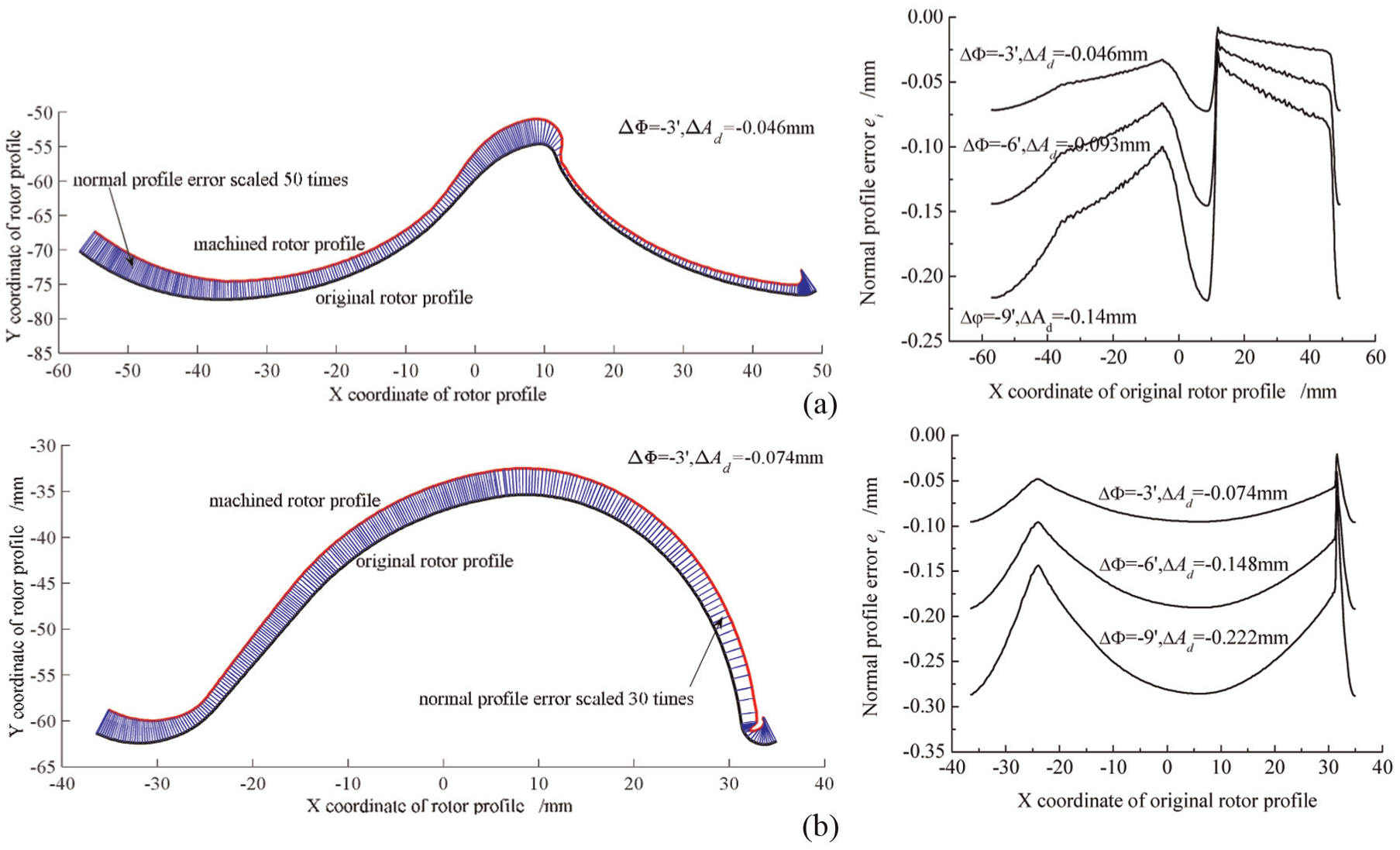
Effects of installation angle error and center distance error on rotor profile in case (4): (a) male rotor and (b) female rotor.
Table 9 shows the rotor profile errors with the coupled-factor errors for case (4). The decrement of the installation angle and the center distance increases the difference between the maximum normal profile error and minimum error normal profile error
Rotor profile errors in case (4).
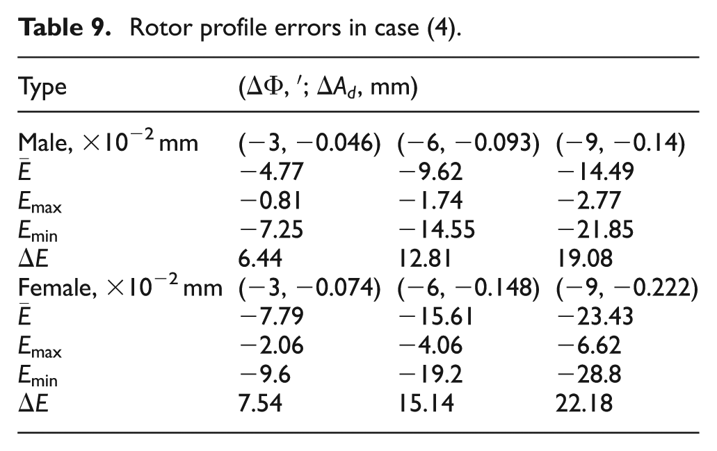
Figure 16 presents the coupling effects on normal profile error for case (4), Figure 16(a) and (b) are for male rotor, Figure 16(c) and (d) are for female rotor. Since the difference between the curve
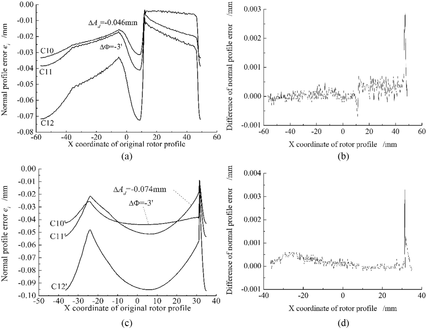
Coupling effects on normal profile error of rotor in case (4): (a) male rotor, (b) male rotor, (c) female rotor and (d) female rotor.
Discussions
According to the above analysis, the installation errors of grinding wheel, including installation angle error, center distance error and axial position error had effects on screw rotor profile. The detailed discussions on the effects were presented in the following.
In the single-factor installation error evaluation, rotor profile was smaller with the decrement of installation angle or center distance, and the reduced amplitude of normal profile error of rotor was proportional to the reduced amplitude of installation angle error or center distance error. The increment of axial position of grinding wheel caused rotor profile to clockwise rotation with a deflection angle.
In coupled-factor error evaluation with installation angle error and center distance error, the effects on rotor profile can be discussed from three aspects. For the opposite effects on rotor profile caused by the increment of installation angle and the decrement of center distance, if one kind of errors was obviously the dominant factor as shown in cases (1) and (2), the effects on rotor profile caused by the coupled-factor error can be regarded as the ones caused by the dominant single-factor error; otherwise, the machined rotor profile was affected as the enlargement of partial profile curve and shrinkage of partial profile curve as shown in case (3). For the same effects on rotor profile caused by the decrement of installation angle and the decrement of center distance, the rotor profile errors are increased significantly in case (4). For the four cases, the linearly superposition effects on normal profile error of rotor with the coupled-factor errors were observed for the installation angle error and the center distance error.
The evaluated effects provide a theoretical basis for error tracking and error compensation caused by installation errors of grinding wheel. For example, if the machined rotor profile is measured to be smaller, it can be inferred that the decrement of installation angle or center distance probably results in the smaller rotor profile based on the above discussions. Since center distance adjustment is often costly and time-consuming, installation angle can be first considered to compensate the profile error. Based on the discussion result that the reduced amplitude of normal profile error of rotor is proportional to the reduced amplitude of installation angle error, the installation angle can be adjusted iteratively until the profile error satisfies the error requirement. If the profile error is still not satisfied with installation angle adjustment, the coupled installation parameters of grinding wheel should be further considered to compensate the profile error. It should be noted that installation parameter adjustment is to compensate rotor profile error as a whole, and it cannot be applicable to local error compensation of screw rotor profile.
Experiment
To verify the above effects of installation errors of grinding wheel on rotor profile, screw rotor grinder named SK7032 from Hanjiang Machine Tool Company was used to machine the female rotor mentioned in Table 1 with installation errors of grinding wheel, as shown in Figure 17. Table 10 provides the three cases of installation parameters of grinding wheel.
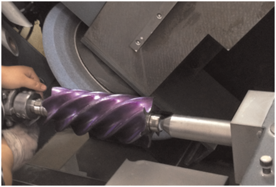
Female rotor grinding with SK7032 grinder from Hanjiang Machine Tool Company.
Installation parameters of grinding wheel.
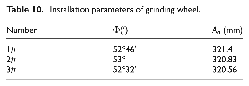
Figure 18 shows the machined female rotor with installation errors of grinding wheel. Profile of the machined female rotor was measured by three-coordinate measuring machine P65 from Klingelnberg Company, as shown in Figure 19.
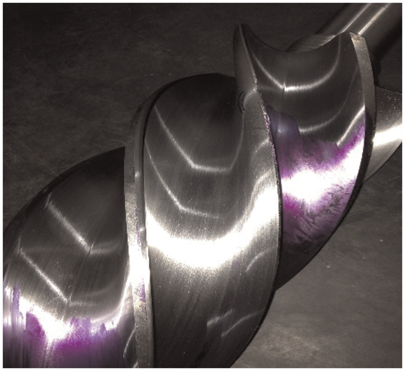
Machined female rotor.
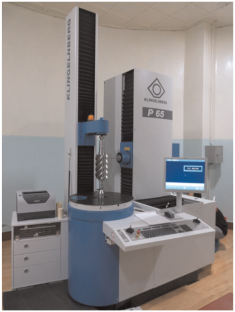
Three-coordinate measuring machine P65.
Comparing parameter 2# with parameter 1#, installation angle error
Comparing parameter 3# with parameter 1#, installation angle error
Three machined profiles of female rotors measured by P65 are shown in Figure 20. Rotor profile under parameter 1# is considered as “datum profile,” and rotor profiles under parameter 2# and parameter 3# are considered as “compared profile.” By comparing “compared profile” with the “datum profile,” the rotor profile errors of experiments and simulation are shown in Table 11.
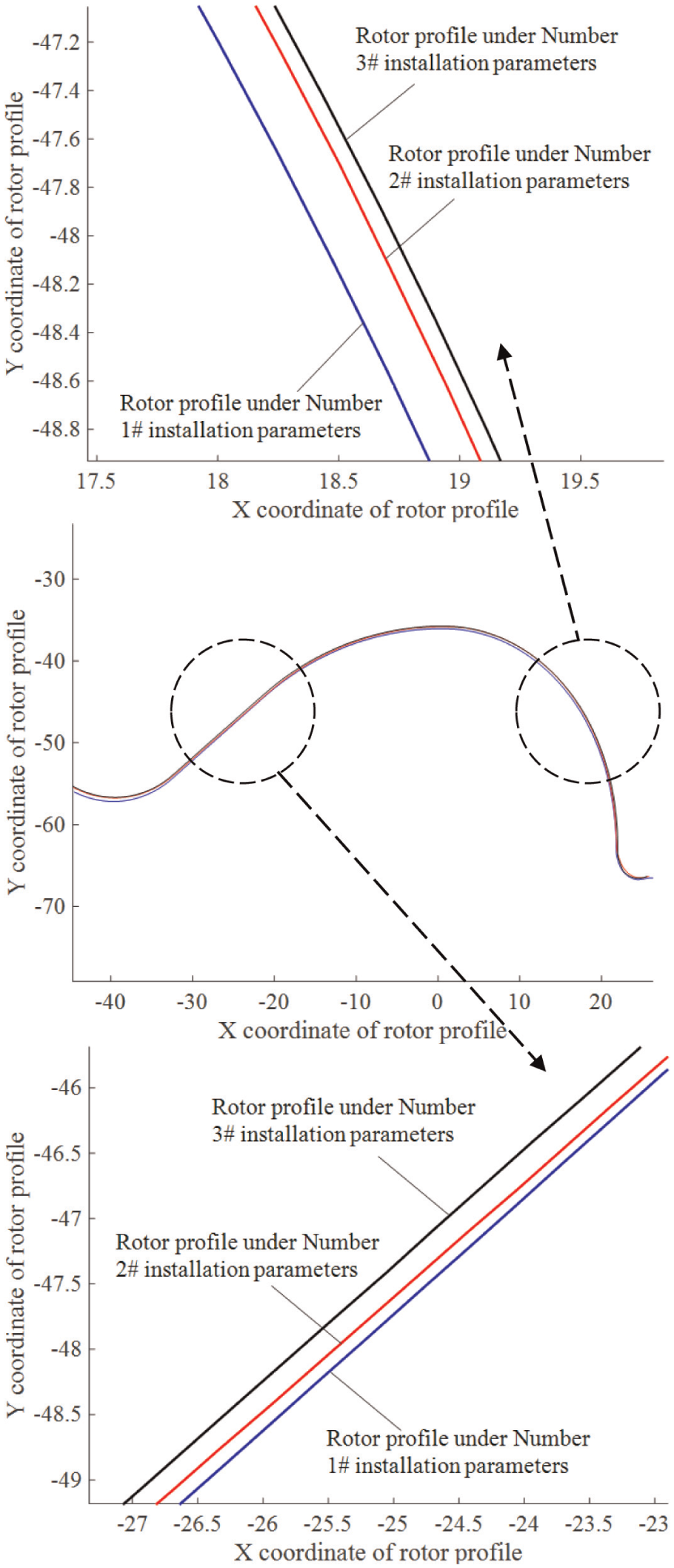
Comparison of rotor profiles under parameters 1#–3#.
Profile error of rotor from experiments and simulation.
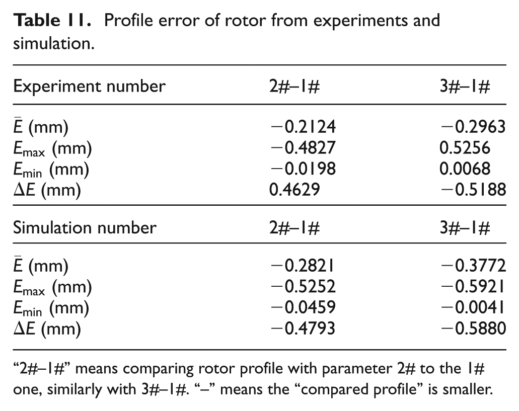
“2#–1#” means comparing rotor profile with parameter 2# to the 1# one, similarly with 3#–1#. “–” means the “compared profile” is smaller.
Figure 20 shows that with the changes of installation parameters, from parameters 1# to 3#, the rotor profile is smaller, which is consistent with the above analytical results. In Table 11, although the rotor profile errors from simulation are greater than the ones from experiment due to other errors during grinding process, the change trend of rotor profile by experiment is consistent with that by simulation. This means the simulation analysis of the effects of installation errors on rotor profile in this article is valuable.
Conclusion
This article proposed a numerical method to evaluate the effects of installation errors of grinding wheel on rotor profile. The screw rotor profile was generated and its error model was established based on coordinate transformation and engagement theory. Depending on the profile error calculation of the obtained models, the detailed error evaluation procedure was presented with discrete rotor profile points. The numerical cases for a couple of intermeshing screw rotors showed the effects of installation errors of grinding wheel on rotor profile by considering both single-factor installation errors and coupled-factor installation errors. And grinding experiments for female rotor by introducing different installation errors were performed to verify the analysis of the numerical cases. Some conclusions were obtained as follows:
The installation errors of grinding wheel, including installation angle error, center distance error and axial position error have effects on screw rotor profile.
Rotor profile is smaller with the decrement of installation angle or center distance, while it is rotated clockwise with a deflection angle caused by the increment of axial position.
If there is a dominant factor in the coupled-factor errors, the effects on rotor profile caused by the coupled-factor errors can be regarded as the ones for the single-factor error.
The linearly superposition effects on normal profile error of rotor are observed for the coupled-factor errors of the installation angle error and the center distance error of grinding wheel.
The above cases show that the proposed numerical method is useful to evaluate the effects of installation errors of grinding wheel on rotor profile. It can be further used to carry out error tracking and error compensation for screw rotor grinding. In the future work, how to obtain adjustment values of the installation parameters should be further studied for efficiently implement this approach in error compensation process. On the other hand, other errors affecting the rotor profile as well as installation parameter errors should also be considered comprehensively to improve accuracy of error compensation for screw rotor. Additionally, the practical evaluation software for this approach can be developed to improve the efficiency of error analysis.
Footnotes
Appendix 1
Declaration of Conflicting Interests
The author(s) declared no potential conflicts of interest with respect to the research, authorship and/or publication of this article.
Funding
The author(s) disclosed receipt of the following financial support for the research, authorship, and/or publication of this article: This work was supported by the National Natural Science Foundation of China (51475244), Chongqing Research Program of Basic Research and Frontier Technology (No.cstc2015 jcyjBX0088), “Six Talent Peaks” Project in Jiangsu Province (2014-ZBZZ-006) and “excellence plans-zijin star” Foundation of Nanjing University of Science and Technology (2015-zijin-07).