
Abstract
Gear hob is an important tool that is most used in gear processing. Hob accuracy directly exerts an overwhelming influence on the quality of the processed gear. Generally, the hob tooth profile accuracy is mainly determined by relief grinding process. Studies on tooth profile errors of gear hobs caused by severe friction and cutting with the high-speed rotation of the wheel during the form grinding machining of hobs are limited. Thus, a theoretical model of the tooth profile error prediction under different machining parameters was established based on the analysis of coupling influence of high temperature and high strain rate on gear hobs in the relief grinding process. The model was completed on the basis of the dynamic explicit integral finite element method of thermo-mechanical coupling. Through the prediction model, the influence of the grinding depth ap, feed speed Vw and grinding speed Vs on the tooth profile error can be analysed. In addition, an algorithm for accurately calculate the grinding wheel axial profile by combining instantaneous envelope theory and hob normal tooth profile was proposed. The hob relief grinding experiments were carried out using the proposed grinding wheel profile algorithm. The relative error of the prediction obtained by comparing the calculation results of the prediction model with the experimental results is within 10%. Results prove the validity of the prediction model. This finding is greatly important for optimising the accuracy of hob relief grinding.
Introduction
Gear processing is an important basic research, and many new progresses has been made. For example, Calleja et al.1,2 provided new views in free form milling and flank form design of gears. Hsu et al. 3 posed a shaving method for double-crowning by using variable pressure angle shaving cutter. In the gear manufacturing method, hobbing is the most widely used because it has high production efficiency and machining accuracy, and is easier for machine adjustment and tool manufacture.
In hobbing, the accuracy of gears can be enhanced by improving the manufacturing accuracy of gear hobs.4,5 The relief grinding machining of gear hobs is recognised currently as one of the most extensively applied processing technologies in the hob manufacturing industry on account of the characteristics of high efficiency and excellent adaptability.6–8 After reliving, the hob has the disadvantage of large tooth surface roughness, light spots and numerous burrs. Hence, the hob requires to be ground, it is the last essential finish machining in the hob manufacturing process for further improving manufacturing accuracy and durability.
The focus of hob grinding is to grind the side relief surface, so that the increased tooth profile error due to the continuous wear and dullness of hobbing can satisfy the processing requirements. To obtain the accurate tooth profile for relief grinding and further improve the precision of the subsequent gear hobbing, satisfying that the tooth profile error after hob grinding is within the required range is critical. Generally, the main factors that affect the accuracy of hob relief grinding are associated with the grinding wheel axial profile, the gear hob geometry, the gear grinding machine and the relief grinding process.
Considerable studies highlight these influencing factors. A new general algorithm was expressed by Yang and Chen 9 for accurately generating the grinding wheel axial profile based on the spatial envelope theory. The phenomenon of self-intersect curve that currently exists in the form grinding wheel axial profiles for relief grinding gear hobs produces the formation of a larger transition surface size at the sharp position of the workpiece processed by the tool. Thus, Li et al. 10 presented a discrete sharp point vector method to eliminate self-intersection and improve the precision of relief grinding. An equal relief angle method was proposed by Li et al. 11 for reducing the regrind error, considering the gear hob geometry. The relationship between the hob relief angle and the tooth profile errors was analysed by applying the Archimedes relieving motion. This method can also increase the qualified length of hob tooth. An approach for calculating the hob geometry design parameters based on the straight-line lateral cutting-edges was proposed by Radzevich 12 to eliminate the primary origin of errors in hobbing involute gears. Shen et al. 13 conveyed a solution for grinding the crowned face gear tooth profile to optimizing the gear grinding machine. It can be used for tooth profile error modification of worm hobs or grinding cutters on free-form multi-axis CNC machine tools. Tian et al. 14 proposed a new software-defined electronic gearbox applied to the hobbing computer numerical control, and experiments with different gear hobbing methods were carried out to verify its good performance. Liu et al. 15 introduced a method for the relief grinding of a flat double-envelope worm gear hob on multi-axis CNC worm gear grinders, thereby realising that the hob can be automatically relief ground under different cutting-edge shapes and helical angles. For the hob relief grinding process, accurately and intuitively expressing the generalised relation between the relief grinding processing parameters and the tooth surface error is difficult due to the randomness and nonlinearity of the machining process. Establishing a hob relieving grinding processing model through simulation analysis technology can quickly and simply describe the relation between the processing parameters and the simulation results. It is also helpful for the process optimisation and result prediction.
However, the present work deals mainly with the prediction and compensation of thermal errors, force-induced errors in the hobbing process and their coupling effects on the accuracy of hobbing. For instance, to study the coupling effects of thermal errors and force-induced errors on manufacturing precision during high-speed dry gear hobbing, the numerical simulations on the temperature distribution of the working devices, the force-induced errors and thermal errors generated in the gear hobbing process were performed by Li et al. 16 Similarly, Liu et al. 17 carried out a numerical simulation analysis under the conditions of steady-state and transient-state of the dry gear hobbing machine spindle assembly thermal deformation for predicting the temperature and deformation during gear machining. Sun et al. 18 established models on gear hobbing geometric deviation prediction and optimisation based on a large number of hobbing experiments by using IPSO and BP algorithms to improve the accuracy of gear hobbing.
The grinding wheel has higher specific grinding energy, and most of the kinetic energy is converted into heat. 19 The temperature of the grinding local area increases rapidly in intense friction and cutting, thereby changing in the metallographic structure of the grinding surface of the hob. Excessive temperature is responsible for various thermal damages to the hob tooth surface, such as surface oxidation, poor phase transformation, tensile residual stress and thermal cracks, 20 further affecting the quality of the hob grinding surface and reducing the hob life. Therefore, the tooth profile deformation under the coupling action of the temperature field and the stress field should be considered to improve the accuracy of relief grinding.
In view of the hob tooth profile deformation concern of the high temperature and high strain rate coupling under the action of grinding heat in the hob grinding process, the dynamic explicit integral finite element method of thermo-mechanical coupling is applied initially to complete the hob numerical simulation analysis. Then, the RSM prediction model of the hob tooth profile error in the case of different machining parameters was established on the basis of the FEM simulation results. Finally, experiments with respect to the hob relief grinding and tooth profile error detection were carried out on the proposed model of grinding wheel axial profile on the basis of the hob relief grinding theory. The experimental results verify the accuracy of the prediction model and quantify the coupling effects of grinding heat and force on the hob relief grinding precision.
Thermo-mechanical coupling numerical simulation of hob relief grinding
For the convenience of manufacturing and grinding, the gear hob with zero-degree rake angle is generally applied for hobbing. The diagram of relief grinding movement relation at an arbitrary moment is established according to the radial relief grinding movement between a grinding wheel and a hob. As described in Figure 1, the grinding wheel performs relief grinding on the tooth side surface of the right-hand gear hob with straight chip-hold grooves and zero-degree rake angle. The radical relief grinding movement consists of the hob rotation, the grinding wheel rotation, the hob translation along its axis, and the grinding wheel feed motion along the hob radial direction.
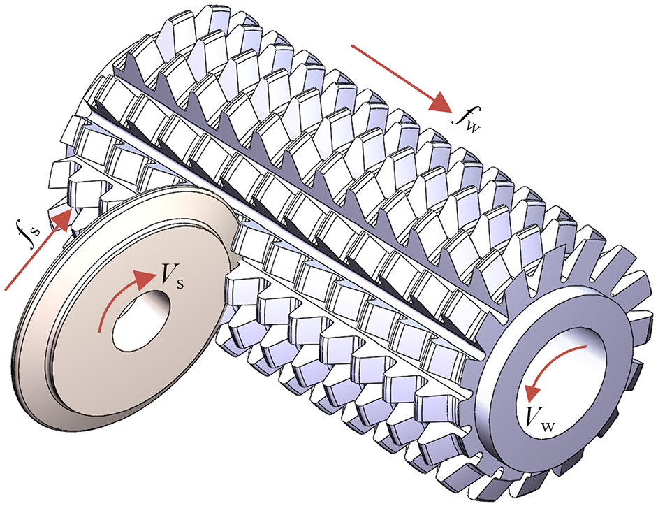
Radical relief grinding movement of a grinding wheel.
Mathematical model of hob grinding temperature field
In the process of grinding tooth surface, the instantaneous contact between grinding wheel and hob tooth surface forms surface heat source moving at the specified speed, resulting in temperature momentary variation of hob tooth surfaces. The gear hob grinding process can be transformed into 3D heat transfer modelling in accordance with the energy conservation principle and the heat transfer theory. In the 3D transfer solution domain
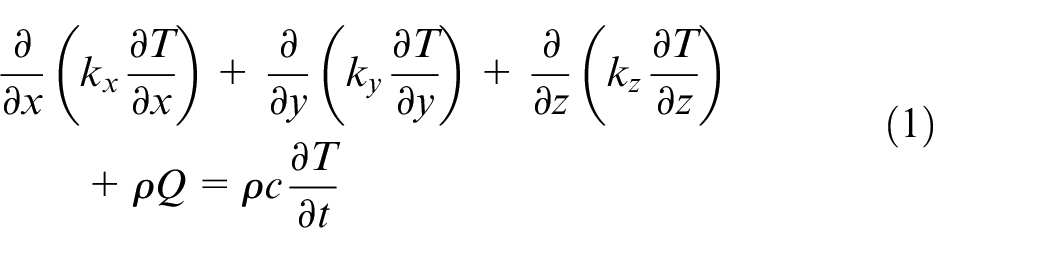
where

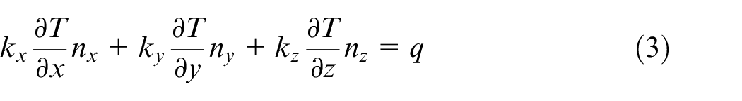
where T0 is the initial temperature of the tooth surface to be ground; nx, ny and nz are the exterior normal directions of the boundary; q=q (Γ, t) represents the given heat flux on the Γ2 boundary.
In accordance with the heat conduction differential equation of the grinding temperature field and the boundary conditions, the gear hob is divided into finite elements. Then, the heat flow load in the grinding process is applied to the elements on the boundaries, namely, the entire temperature loads is discretised into the node loads equivalent to the actual loads. The mathematical model of the finite element method for the transient grinding temperature field of hob tooth profile can be obtained after bringing in the two types of boundary conditions, which can be described in matrix form, as follows:
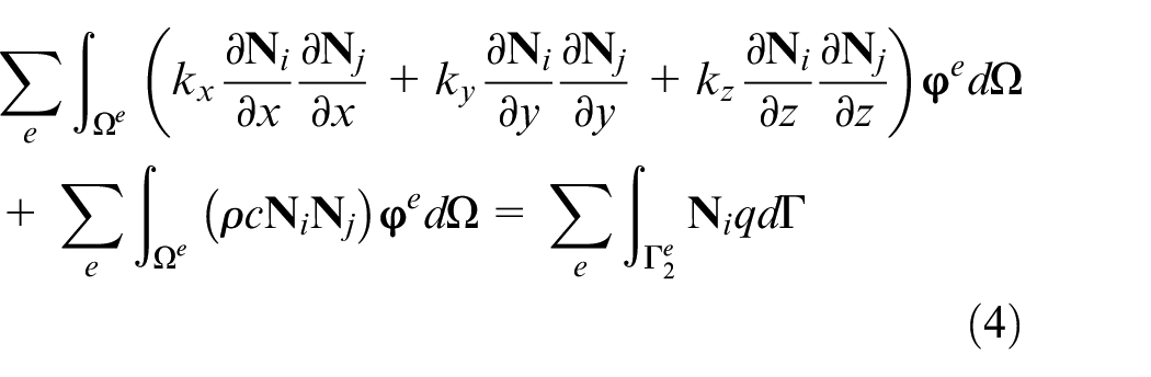
where
Moving heat source model
The process can be regarded as form grinding considering that the grinding wheel axial profile and the hob tooth side form an envelope surface in an arbitrary moment during hob relief grinding. Commonly, the grinding wheel moves along the workpiece surface, and the heat source generated by grinding also moves along the hob at the same speed. The machining process is similar to surface grinding, and accordingly, the theory of surface grinding is also applicable to the relief grinding of gear hobs.
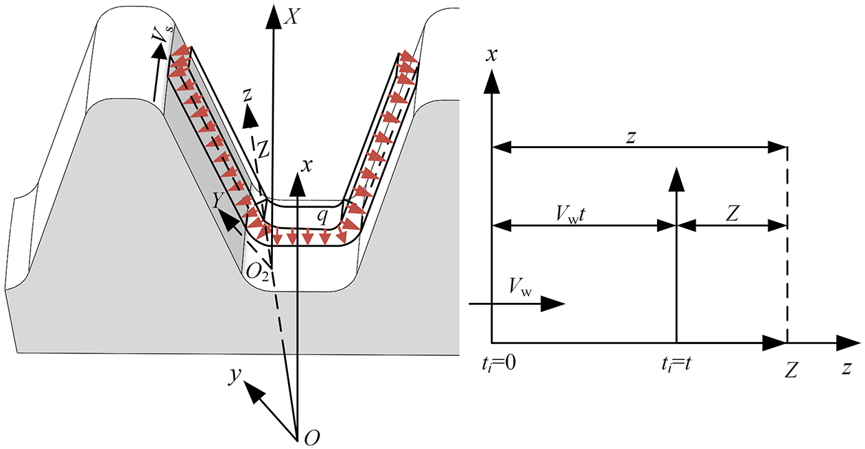
In accordance with Jaeger’s moving heat source theory, a theoretical model of gear hob relief grinding moving heat source for numerical simulation analysis of grinding heat is established. In addition, the convection heat transfer of grinding fluid is neglected because dry grinding is adopted in the experiment. A single tooth profile intercepted from the hob as a whole is used for modelling to satisfy the calculation and simulate the hob grinding process accurately. As described in Figure 2, the sketch of the simplified moving heat source model of the hob grinding shows that the moving distance of the heat source along z axis from time ti = 0 to time ti = t is equal to Vwt. The rectangular heat source distribution is adopted as the loading type of the hob grinding heat source, and the total heat flux q generated is uniformly distributed in the grinding zone, expressed as follows:
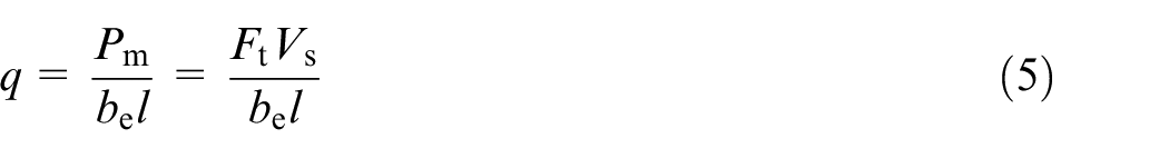
where Pm is the net grinding power; be is the grinding width; l represents the wheel-workpiece contact arc length,
Sketch of the simplified moving heat source.
Heat flow distribution model of temperature field in the grinding zone
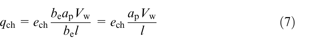
Under the condition of dry grinding, the heat generated is transferred to the tooth surface, grinding wheel and grinding debris by heat conduction. Consequently, the total heat flux q in the grinding zone mainly consists of the heat flux transferred to the tooth surface qw, the heat flux conducted to the grinding wheel qs and the heat flux qch carried away by the grinding debris.21,22 On the basis of the principle of energy conservation, it can be obtained by the following:

On the basis of Malkin’s 23 research, the heat carried away by the grinding debris can be calculated by the ultimate grinding energy ech, the removal rate of tooth surface material per unit time and the contact zone per unit area. It can be determined using the following equations:
A large amount of kinetic energy is consumed by the grinding wheel when grinding the gear hob, and almost all will be converted into heat energy in the grinding zone. In the single abrasive grain sliding hypothesis model proposed by Hahn, the heat flux transferred to the grinding debris is irrelevant to this model. The heat distribution ratio Rws conducted to the hob tooth surface during dry grinding is denoted as follows:
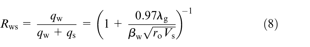
where
The heat flux transmitted into the hob tooth surface according to equations (6) and (8) can be obtained as follows:

Finite element numerical simulation
A great deal of grinding heat is generated during the grinding process. The material properties of the tooth surface, such as thermal expansion coefficient, thermal conductivity, density and Poisson’s ratio change at various temperatures, resulting in thermal stress. The tooth surface is deformed under the action of thermal stress, and the generation of thermal deformation changes the frictional contact state between the abrasive grain and the workpiece, consequently affecting the grinding heat generation. The dynamic explicit integral finite element method of thermo–mechanical coupling is used to simulate and analyse the hob form grinding to analyse the deformation caused by the coupling of high temperature and high strain rate more accurately. The subroutine is written by the ANSYS parameterized design language APDL, and the analysis process is described in Figure 3.
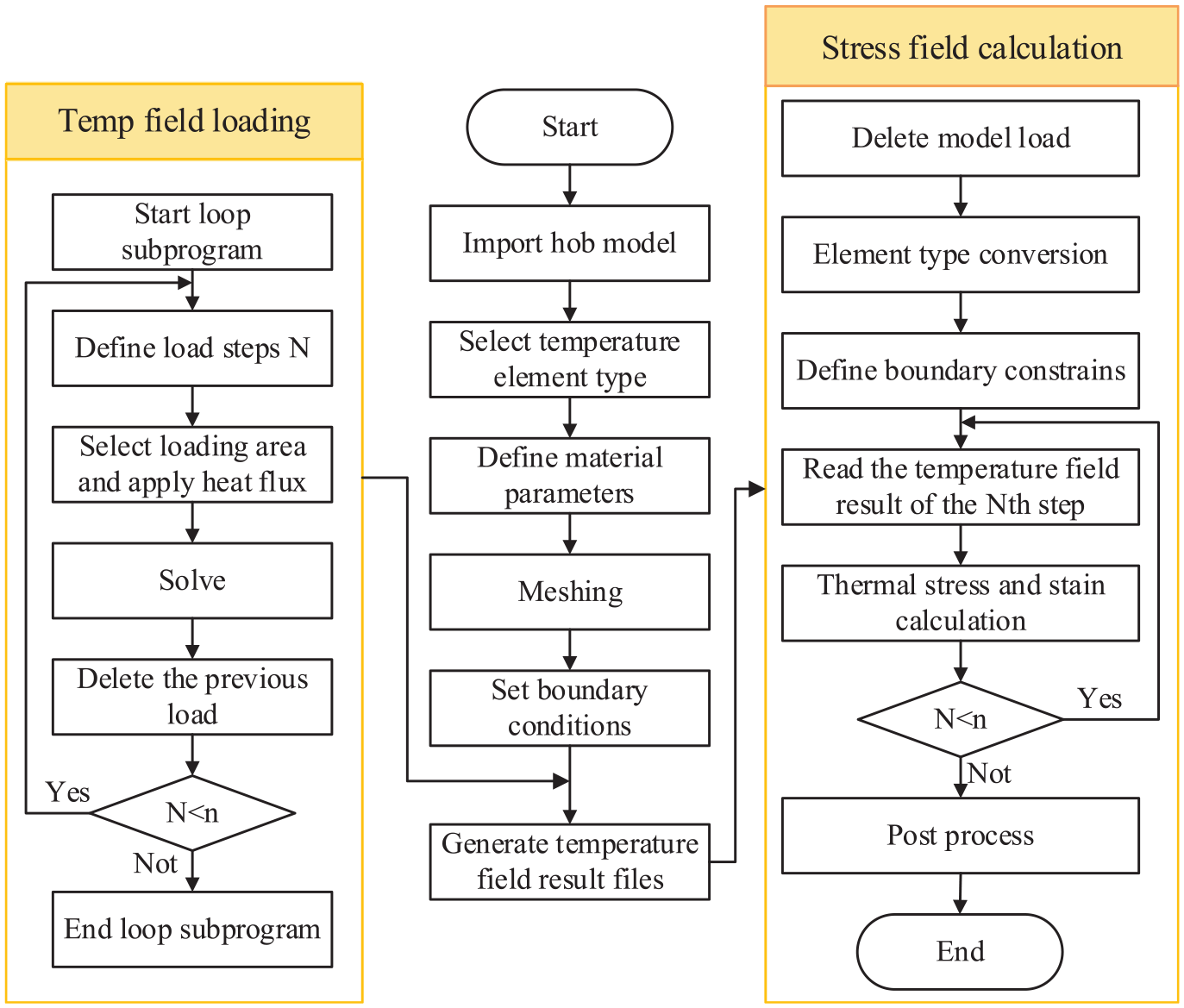
Thermo–mechanical coupling simulation analysis process of hob relief grinding.
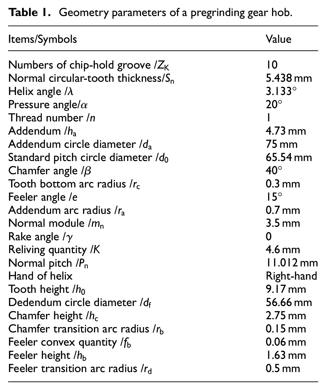
In the simulation, assuming that the hob tooth surface is insulated from the air and ignoring the convection heat transfer of air, only continuous heating, uniform and constant surface heat source is added in the grinding zone. Without considering the heat radiation and grinding vibration, the heat source moves continuously in the grinding zone during simulation. Thus, the temperature and deformation at different positions of the tooth surface change with time. Figure 4 signifies the temperature change and deformation of the tooth surface of a pregrinding gear hob during relief grinding process. The geometric parameters of the pregrinding gear hob are provided in Table 1. The grinding parameter values of the grinding speed, feed speed and grinding depth in Figure 4 are 35 m/s, 4500 mm/min and 0.025 mm, respectively. The figure shows that tooth surface temperature continuously rises from the beginning to the end of grinding. The heat in the tooth surface chamfer, feeler and other corners are hardly prone to dissipate, resulting in heat concentration and high temperature. The relatively large thermal deformation of hob tooth surface is yielded due to the increase in grinding temperature, leading to an increased tooth thickness. In addition, the position with the greatest deformation is located near the tooth top under the current grinding conditions, and the maximum hob tooth surface deformation is 16.4 μm.
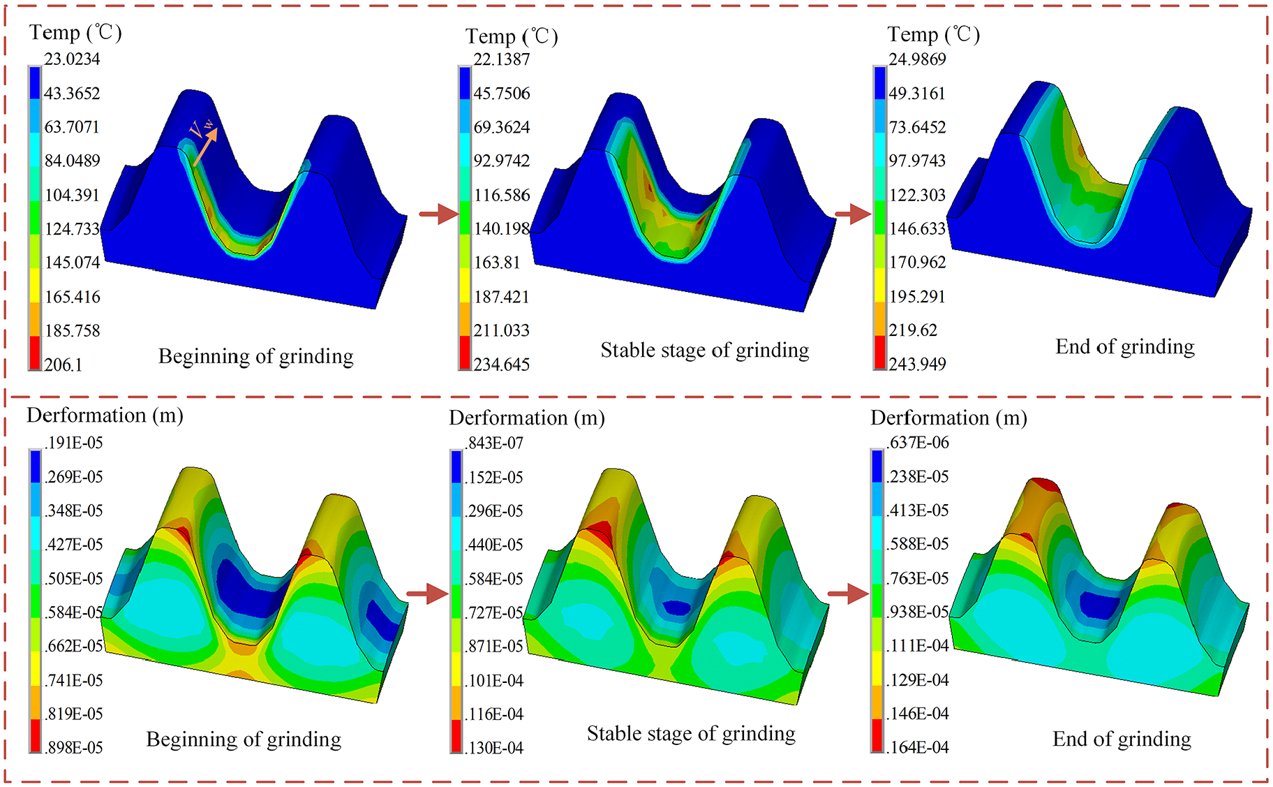
Temperature change and tooth surface deformation of gear hobs during relief grinding.
Geometry parameters of a pregrinding gear hob.
The influence of grinding parameters and tooth surface deformation of gear hobs are shown in Figure 5 based on the simulation results. It can be observed that the hob tooth surface deformation increases with the grinding depth and grinding speed and decreases with the feed speed. Therefore, under the condition of catering for the demand of a specified processing efficiency, smaller grinding depth, grinding speed and larger feed speed can be used to obtain a smaller tooth surface deformation in hob grinding process.
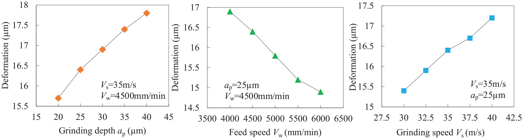
Influence of grinding parameters and tooth surface deformation of gear hobs.
Prediction of tooth profile error of hob after grinding
Polynomial RSM model
Response Surface Methodology (RSM) is an optimisation method that combines reasonable experimental design with mathematical statistics. Testing the given set of design points by adopting the experimental design method, the functional relationship between the response target and the design variables is regression-fitted, to obtain the optimal combination of design variables and optimise the objective function. RSM considers the random error of trials. When the experimental area is close to or located in the optimal area, a second-order polynomial response surface model (equation (10)) can be applied to approximate the response surface. It is an effective means to solve the related problems of nonlinear data processing. Furthermore, each level of the experiment can be continuously analysed in the process of searching optimization. As a consequence, the prediction model obtained by RSM is continuous, as follows:
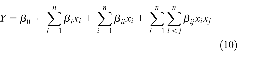
where x is the influencing factor variable; i and j are the serial number of the influencing factor variable; n is the number of influencing factor variables; Y is the predicted response value;
In the interest of judging whether the fitted polynomial response surface proxy model can appropriately express the response relationship, the determination coefficient R2 is frequently used to test its accuracy. R2 can be denoted with the following equation:
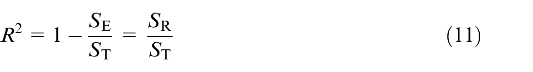
where parameters SE, ST and SR represent the regression sum of squares, the total deviation sum of squares and the regression sum of squares, respectively. Generally, the closer R2 is to 1, the higher the accuracy of the model.
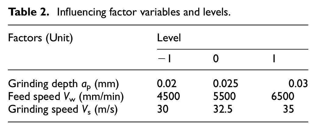
With the purpose of analysing the influence of process parameters on the hob tooth profile error during the relief grinding process, the FEM numerical simulation result of thermo-mechanical coupling is the basis of calculation. The Box–Behnken test design method is utilised for initial sampling. The grinding depth ap, feed speed Vw and grinding speed Vs are selected as influencing factors according to actual working conditions. Finally, a response surface model with the deformation of the hob tooth surface as the objective function is established.
Each influencing factor variable takes three levels, coded with (−1, 0, 1). ‘0’ is regarded as the centre point, ‘1’ is the high level, and ‘−1’ represents the low level. The reasonable experimental influence factor variables and levels designed according to the actual machining process parameters of hob relief grinding are briefly provided in Table 2.
Influencing factor variables and levels.
Results and discussion
The FEM results according to RSM are subjected to multiple regression analysis. The second-order polynomial regression equation of the tooth surface deformation Ffs on the influencing factor variables is gained. It can be expressed as follows:
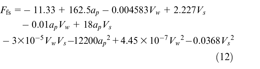
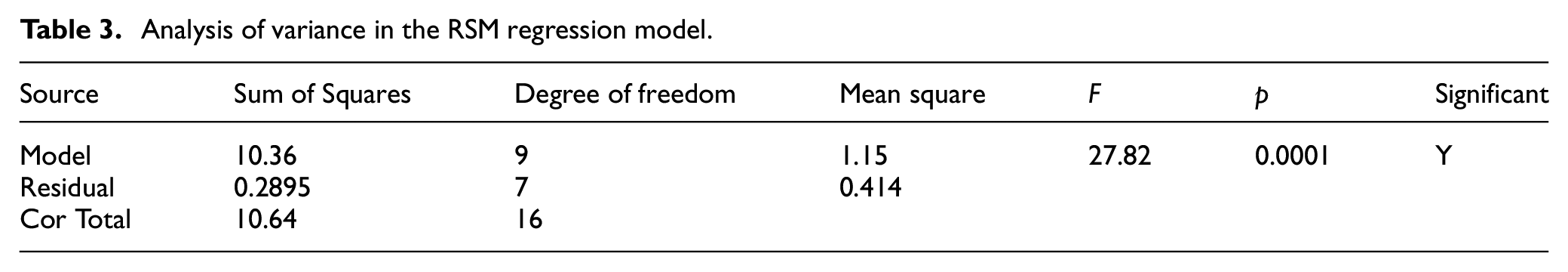
The comparison between the predicted value of the hob tooth surface deformation and the actual value obtained by the fitted regression model is shown in Figure 6. The figure shows that the distribution of actual value and predicted value exhibits an evident linear relationship. At the same time, the significance analysis of the established RSM regression model is carried out, and the results are shown in Table 3. P and F in Table 3 represent the significance of the correlation coefficient. Generally, the factor has a substantial impact on the objective function when p is less than 0.05. The smaller the p-value, the more significant the impact of the corresponding factor. The p-value is equal to 0.0001, indicating that this regression model is significant. In addition, the determination coefficient R2 of this model is 0.9928, and the established regression equation possesses favourable fitting performance. Accordingly, the response surface model constructed by RSM, which considers the hob tooth surface deformation as the objective function performs high credibility.
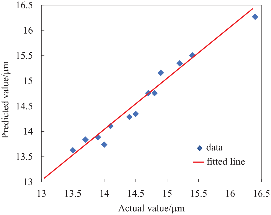
Distribution diagram of predicted and actual values of hob tooth surface deformation.
Analysis of variance in the RSM regression model.
Experiment and discussion
Wheel axial profile model for relief grinding pregrinding gear hob
Establishment and transformation of the relief grinding coordinate system
As described in Figure 8, a spatial moving coordinate system of the relative movement based on the relative position of the grinding wheel and the hob is established. It provides details of the coordinate system of the gear hob in an arbitrary moment after the start of the relief grinding.
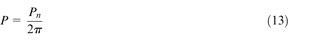
where Pn is the hob normal pitch,
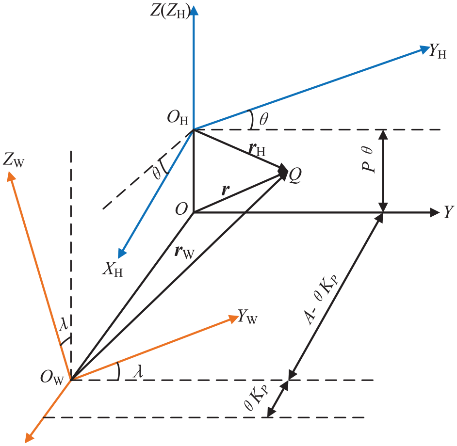
Reliving space coordinate system.
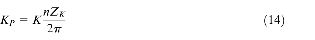
When the reliving quantity is K, the number of chip-hold groove is Zk, and the thread number is n. The grinding wheel radical movement distance when the hob rotates in a unit radian can be denoted as follows:
Suppose that point Q displayed in Figure 8 is an arbitrary meshing point during the gear hob grinding process. The radius vectors of the meshing point respect to origins O,


where
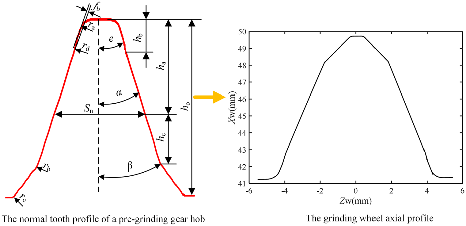
Grinding wheel axial profile based on the normal tooth profile of a pregrinding gear hob.
Computation model of grinding wheel axial profile
The angular velocity of the grinding wheel can be set to zero because the grinding wheel rotation motion exhibits no effect on the form movement of hob relief grinding. Assuming that the rotational angular velocity of the hob is

Based on the fundamental principle of hob relief grinding, the hob side relief surface is a line contact conjugate surface formed by grinding wheel working surfaces and gear hobs for the grinding movement. Furthermore, the contact line possesses the characteristic of momentary change. At the meshing point, the meshing condition of the two curved surfaces in space should satisfy the tangency, and the relative motion speed is on the common tangent plane. Therefore, the existence of a common normal vector at the meshing point between the grinding wheel envelope surface and the hob cutting edge, as well as the vector is perpendicular to the relative speed. In the grinding wheel coordinate system

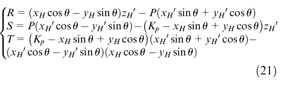
According to equation (20), the relative rotation angle of the hob and grinding wheel at any time can be obtained by Newton iteration method. Substituting rotation angle into equation (16) can obtain the coordinate value of the contact point in the grinding wheel coordinate system, which can be denoted as follows:
Numerical example
Obtaining a precise hob tooth side shape is necessary to improve the relief grinding accuracy of the hob. During the grinding process, the gear hob tooth profile should be calculated before the axial profile of the grinding wheel is obtained because the hob side relief surface is the enveloping surface of the wheel axial profile. The more standard hob normal tooth profile is selected as the basis for calculating to reduce the regrinding error produced by the different rake angles and chip-hold grooves. 9 A re-grinding hob normal tooth profile with the characteristics of straight chip-hold grooves and zero-degree rake angle is described in Figure 8. The normal tooth profile consists mainly of the major cutting edge, the chamfer, transition arcs, the tooth bottom and addendum arcs, dedendum transition cutting edge, the feeler, and the straight line of the top edge. After substituting the values of the main parameters of the tooth profile each part into the equations to obtain the normal tooth profile, the grinding wheel axial profile demonstrated in Figure 8 can be obtained on the basis of the instantaneous contact conditions. The geometry parameters of the pregrinding hob are listed in Table 1.
Experiment setup
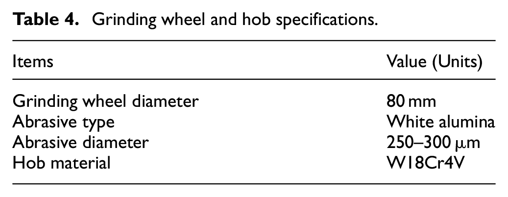
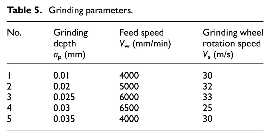
Related experiments were carried out to verify the accuracy of the tooth profile error prediction model. The experiments are composed of the following main parts: grinding wheel dressing and hob relief grinding, as shown in Figure 9. The parallel dressing method is applied to dress the grinding wheel on the basis of the wheel axial profile model established in this study, and the dressing tool is a diamond roller. The high-precision dressing movement of the grinding wheel is not only a prerequisite for the subsequent hob grinding movement, but also a vital guarantee for obtaining the accurate hob in the entire system. Then, the dressed grinding wheel is used to grind the gear hob to satisfy the demand of hob tooth accuracy. The specifications and grinding parameters of the tool and workpiece are listed in Tables 4 and 5, respectively.
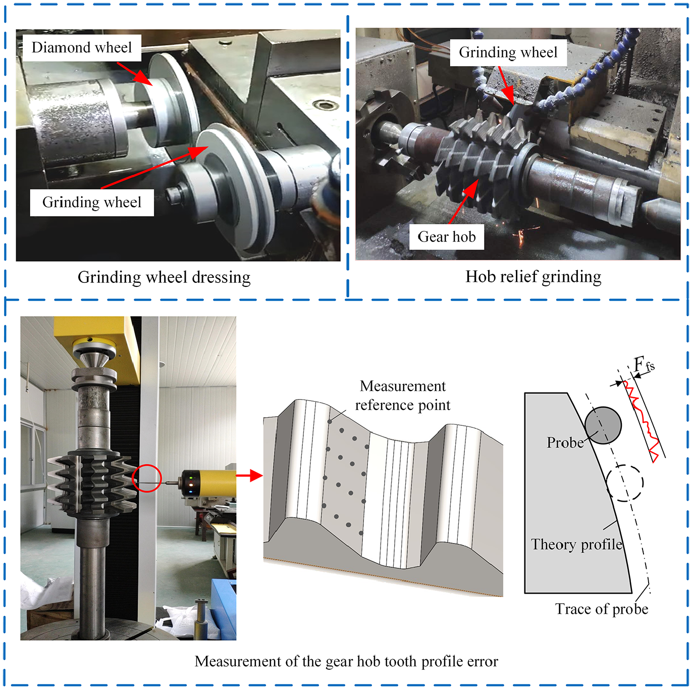
Experiments of relief grinding and measurement of the gear hob tooth profile error.
Grinding wheel and hob specifications.
Grinding parameters.
The hob tooth profile error is measured after the hob relief grinding is completed. Generally, the tooth profile error Ffs of the hob is the difference between the maximum deviations and the minimum deviations of the actual position of the detection points on the hob tooth surface from the theoretical position on the envelope helical line. After inputting hob geometric parameters, test standards and other parameters into the measuring centre, probe is used to detect the clamped gear hob. Figure 9 displays the measuring process of hob tooth profile error. The measurement position is along the tooth profile, which is divided into 16 measurement reference points evenly from root to top. In addition, the measuring device is JINGDA JE20 gear measuring centre, and the hob tolerance regulation is DIN 3968.
Experiment result discussion
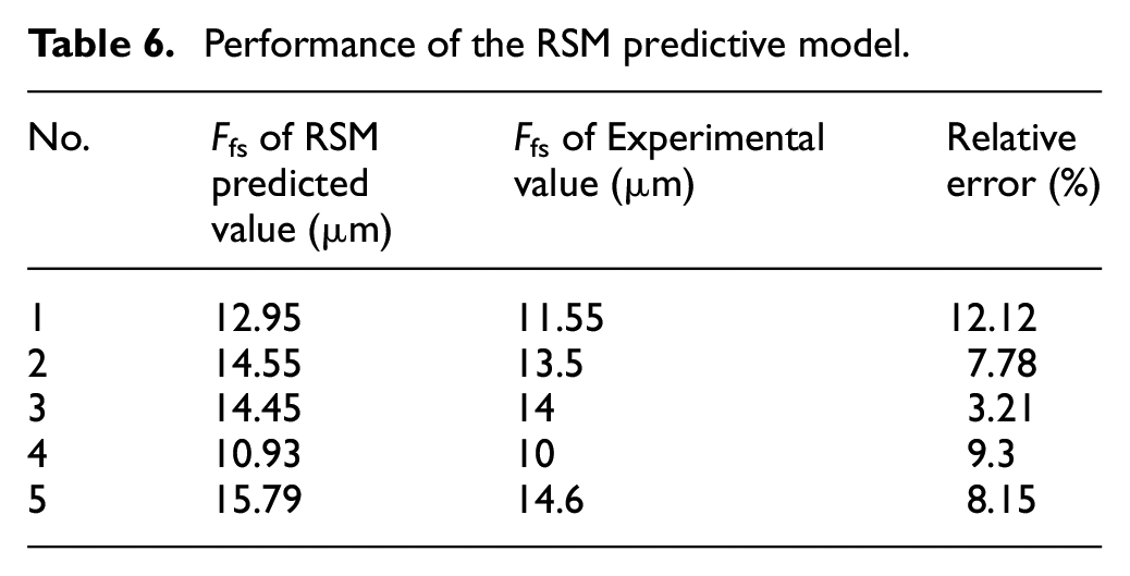
In the case of applying hob geometry parameters and grinding parameters of Tables 1 and 5 for the experiments, the results of tooth profile error measured are listed in Table 6. Based on the hob tolerance regulation DIN 3968, the hob accuracy obtained by the first four group experiments can be regarded as class A, and the fifth group can reach class B. The comparison between the calculation results of the RSM prediction model and the experiment results is shown in Figure 10. The predicted values under these grinding parameters are all larger than the experiment values. This phenomenon is due to the fact that the maximum value of tooth surface deformation obtained by the thermo–mechanical coupling simulation model of hob relief grinding is close to the tooth top, and the experimental results are dominated by the tooth profile error detected by the cutting edge. Accordingly, the RSM prediction model based on the FEM simulation results is theoretically larger than the tooth profile error obtained by the experiments. The relative error of the prediction obtained by comparing the calculation results of the RSM prediction model with the experimental results is shown in Table 6. The maximum relative error in Table 6 is 12.12% and the minimum is 3.21%. Most errors are within 10%. Therefore, the RSM model has a good performance for the hob tooth profile error prediction.
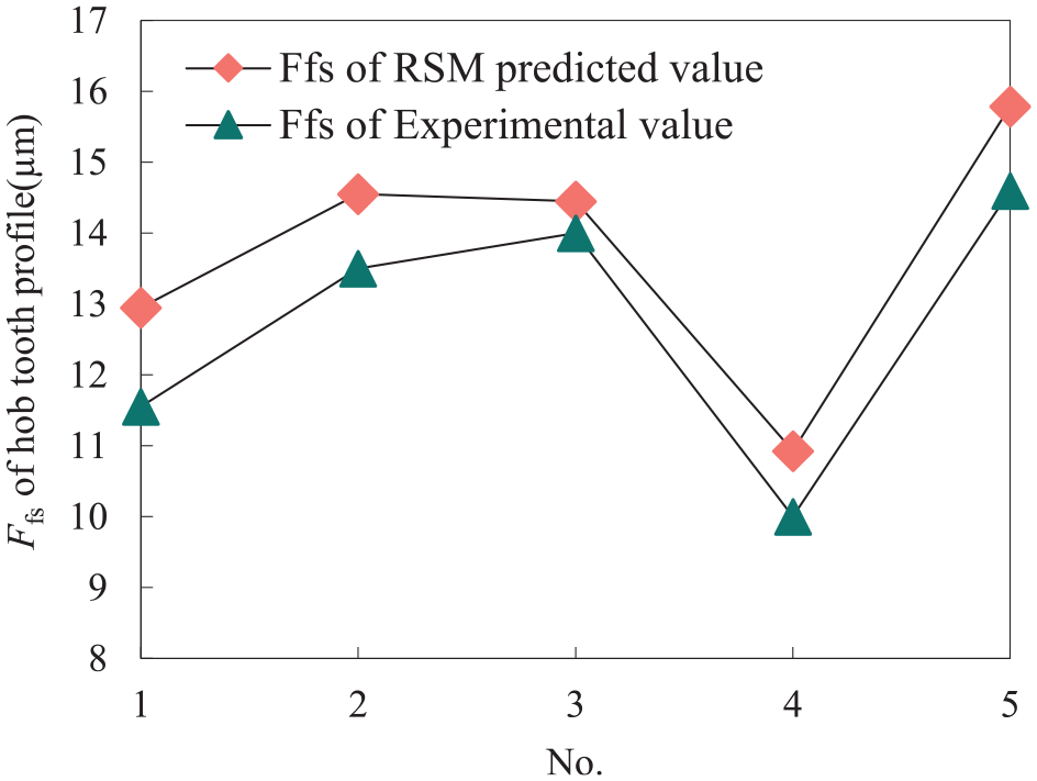
Hob tooth profile error distribution.
Performance of the RSM predictive model.
Conclusions
Relief grinding technology plays an exceedingly indispensable role in the production of gear hobs. Increasing the precision of relief grinding improves the hobbing accuracy. Aiming at the issue of the hob tooth surface deformation under the action of grinding heat in the hob relief grinding process, the gear hob is analysed based on numerical simulation and experiments. The tooth profile error prediction under different processing parameters can be quickly obtained. According to the analysis results, related contributions and conclusions can be briefly drawn, as follows:
Based on the theory of the grinding moving heat source and the rectangular heat source distribution model, a 3D temperature field simulation model for form relief grinding of the pregrinding hob is established. The dynamic explicit integral FEM of thermo–mechanical coupling was applied to carry out a numerical simulation analysis on the form grinding process of hobs. As a consequence, the precise analysis of the temperature field and thermal deformation of the form grinding of gear hobs was completed.
The RSM model for predicting hob profile errors under different machining parameters is established based on the results of the thermo–mechanical coupling FEM numerical simulation of hob relief grinding. The influence of grinding parameters on tooth surface deformation can be obtained, thereby providing a basis for avoiding grinding burns and large tooth profile errors.
In the process of relief grinding, the standard normal tooth profile is used in place of the rake face as the specific conjugate surface meshing with the grinding wheel in accordance with the relief grinding principle of gear hobs. A typical pregrinding hob is considered to obtain the model of grinding wheel axial profile.
Experiments on grinding wheel dressing, hob relief grinding and tooth profile error detection were carried out to verify the RSM prediction model. The measured tooth profile errors are all highly consistent with the theoretical prediction model. The finding plays a pushing role in optimising the hob grinding process and improving the precision of the relief grinding.
The theory and experiment are based on the conditions of dry grinding. Further research is required for the precise thermo–mechanical coupling simulation and verification of hob relief grinding with coolant. In addition, the proposed method only considers the prediction of the tooth profile error after relief grinding. Observing other detection parameters of the hob, such as the lead error of the chip-hold groove and the tooth thickness error is difficult. Therefore, the possibility of realising more hob detection parameter predictions can be explored in the future research.
Footnotes
Declaration of conflicting interests
The author(s) declared no potential conflicts of interest with respect to the research, authorship, and/or publication of this article.
Funding
The author(s) disclosed receipt of the following financial support for the research, authorship, and/or publication of the article: All the authors of this article gratefully acknowledge the help and support of National Key Research and Development Project of China (2018YFB2001503).