
Abstract
This study consisted in investigating parameters that significantly influence the spray efficiency of minimum quantity lubrication in a milling tool with inner channels. An initial experimental approach was used to estimate the oil mist consumption and outlet particle velocities with different inlet pressures, for different shapes of inner channels, without rotation (static part). An experimental versus simulation comparison was undertaken between outlet velocities as a function of inlet pressure. The Reynolds-averaged Navier–Stokes model with the Lagrangian multiphase models was validated by comparing experimental and numerical outlet velocities for different inlet pressures. A numerical rotating tool with inner channels was used with the validated model in the second numerical simulation to analyze the influences of inlet conditions (inlet pressure) based on the tool shape and the rotation velocity, in a dynamic approach. The main objective of the oil mist is to reach the cutting edge (qualifying the minimum quantity lubrication spray efficiency) depending on the inlet conditions (inlet pressures) and the machining configurations (rotation velocities) by analyzing the streamlines of the oil mist particles. The study pointed out the tool design effect combined with its rotation velocity on the oil mist capability to reach the cutting edge. This study offered a trend of parameter sets to provide correct inlet parameters based on machining configurations. At high rotation speed, the inlet pressures needed to be high enough to counter the aerodynamic effects occurred by the tool design.
Keywords
Introduction
Minimum quantity lubrication (MQL) has been used extensively in various mechanical industries (automotive, aeronautic, etc.). The MQL process offers very low oil consumption and beneficial effects on machining (surface state, increased tool life, etc.).1,2
The MQL process involves the use of a mixture of very small oil particles and air pressure created by an external mixing device. These particles are then transferred through channels with high air pressure and velocity and sprayed on the tool. 3 Most MQL equipment has an external nozzle that sprays the oil mist directly onto the cutting edge, mainly for drilling and milling processes.4,5 This technique is quite easy to use, as the nozzle can be adjusted and positioned manually in relation to the cutting edge. However, nozzle placement is important as the flow can end up slightly or completely off the cutting edge.5,6 As lubrication is achieved by an external nozzle in drilling, it is necessary to point the nozzle at the cutting edge. Oil quantity must be high enough (more than 50 mL h−1) and the output velocity of the oil–air mixture must be high enough to enter the tool–workpiece contact point. 7 Moreover, air supply and oil supply have to be considered because they have significant effects on the cutting force (and thus tool power) and surface roughness and tool wear. Better results have been reported with 10–14 mL h−1 oil mist flow rate. 8
The idea is to free operators from accurate position of the external nozzles which can be different from operators or get moved during machining. The oil flow rate must be as small as possible (<15 mL h−1), for better results, as the air flow rate to decrease machining energy consumption. This approach consists in designing rotating tools (for drilling or surfacing process) with inner channels, as seen in Figure 1. It allows the micro-lubricant coolant to reach the cutting edge, better than the external nozzle.4,7
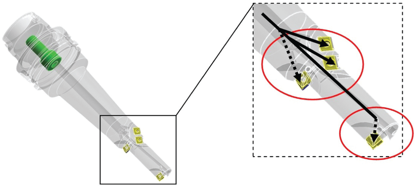
Example of an internal channel (black arrows) in a boring tool, used to spray the oil mist on the carbide inserts (in red circles).
Some cutting tools are equipped with inner channels which transfer the oil mist directly from the mixing device onto the cutting edge. Such channels have mainly been used in turning or grooving processes, where no particular internal geometry studies were required.9–11 Although this type of inner channel does already exist, it is still not used in drilling 12 on specific tools with carbide inserts or in milling. Such tools have quite complex boundary conditions such as rotation speed, external shape leading to aerodynamic effects and milling conditions (surfacing, contouring, etc.), but there are few articles on lubrication of milling machining via inner channels. All studies to date have focused on external MQL.5,13 Aoyama’s 1 study dealt with the influence of spindle rotation and inlet pressure on particle sizes in numerical simulation. His results showed the influence of pressure and the effects of rotation of the channel on particle size with STAR-CD numerical simulation software. It is clear that small particle sizes (∅ < 1 µm) are much less subject to the effects of rotation, and when there are more small particles than particles in the range of ∅ 10 µm (ratio of 1:5).
The type of oil has a significant effect on the conservation of particle size according to the flow turbulence inside the channel; a minimum quantity of lower viscosity lubricant is preferred for drilling processes as it is able to penetrate into the borehole. 4 On the other hand, high-viscosity oil reduces the oil concentration in the oil mist and generates small particles and is preferred for milling processes. 13
Numerical simulation is required to observe and explore oil mist behavior. Li et al. 14 gave an overview of the Reynolds-averaged Navier–Stokes (RANS) flow pattern which has been widely used for simulation of continuous flow. The multiphase models developed to date have given very good results regarding particle behaviors. The Euler–Lagrange (E–L) model has been widely used for diphasic flow study.15–17 Moreover, the standard k–ε turbulence model is easily integrated into the E–L model. The oil mist is constituted of very small particles of about 0.1 µm < ∅ < 100 µm. The inertia can thus be overlooked in the continuous phase flow, as can the particle interactions. The dispersed phase therefore has no influence on the continuous phase behavior. 18 Particle tracks can be studied with the Lagrangian model by analyzing their velocities. 19
The aim of the study consists in optimizing the inlet conditions (inlet pressures) as a function of outlet configurations (rotation speed and with or without nearby workpiece) in order to spray the oil mist onto the cutting edge efficiently.
The first part is dedicated to validation of the numerical model of the oil mist flow with commercial STAR-CCM+ software. Validation is performed by comparing the numerical to the experiment outlet velocities in different channel geometries. 20 The validated model is used to perform the dynamic simulation of a rotating tool, in a second part with standard 45° oriented inner canalizations. The impingement of the oil mist particles is analyzed as function of inlet and outlet configurations.
Validation protocol for oil mist flow motion models
This section presents the correlation between the experimental velocities and the numerical velocities in order to validate the RANS and Lagrangian models. Experiment velocities were obtained from a previous study with an experimental test rig. A characteristic oil mist method was developed which measured the outlet velocities with different geometric models, different types of oil and different inlet pressures. 20 These experiments were simulated according to geometrical and inlet parameters to compare the same physical parameters, such as outlet velocities as a function of inlet pressures.
The rotation of the tool is considered in the next section as a numerical extrapolation to simulate the course and the impingement of the particles on the cutting edge from a dynamic point of view.
Numerical study
The simulations presented in this article were a three-dimensional (3D) steady flow involving particles in an incompressible gas. The flow field was isothermal. Different forms of the averaged equations of motion for the fluid phase have been proposed in the literature. 21 Fluid motion is described by the continuity equation (equation (1)) given by 22
where ρf is the constant density of the gas, αf is the gas volume fraction and uf is the average velocity of the gas. The momentum equation (equation (2)) from the Navier–Stokes equations, for the fluid phase, is given by
where P is the pressure of the fluid, µf is the viscosity of the fluid phase and F is the rate of momentum exchange per unit volume between the fluid and particle phases.
When a reference frame is used to simulate a rotational motion, the basic particle description in STAR-CCM+ involves only its position r and velocity up, defined as follows (equation (3))
where ωp is the rotation speed of the reference frame.
Thus, the Navier–Stokes equation for the particles in a reference frame is as follows (equation (4))
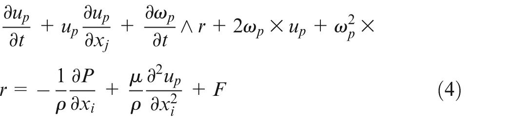
The two last terms on the left part of equation (4) are coriolis and centrifugal forces, respectively.
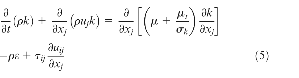
The standard k–ε model is one of the most popular turbulence models used in computational fluid dynamics (CFD). This model of turbulence appears to perform satisfactorily 16 and is composed of two transport equations for the turbulent kinetics k (equation (5)) and its dissipation rate ε (equation (6)) defined as follows
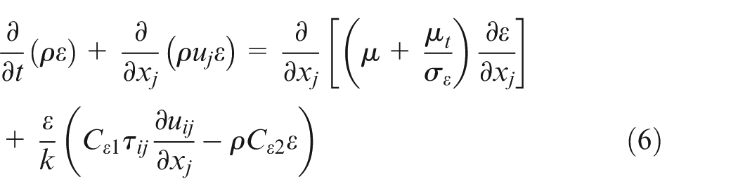

where I is the turbulence intensity set at 0.1 and L is length scale set at 0.001 m in equation (7).
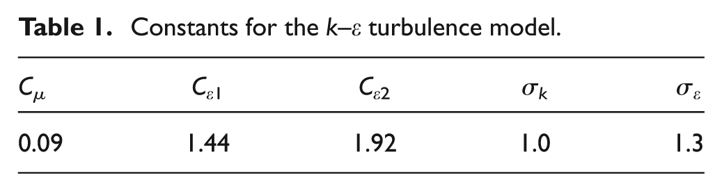
The standard coefficients are given in Table 1 for the k–ε model.
Constants for the k–ε turbulence model.
The previous Eulerian/Lagrangian formulations ignored the interparticle stress term which is the model approach. Moreover, particle–particle interactions were ignored, so the interparticle stress was set at 0.
Numerical simulation input
The numerical simulations were considered as 3D steady state, with a standard k–ε turbulence model. The turbulence dissipation rate was set at 0.1 m2 s−3 and the turbulence kinetic energy was set at 0.001 J kg−1. The inlet and outlet conditions were set as pressures. Different inlet conditions were considered and the initial pressure value was set at an atmospheric pressure of 101,325 Pa. The Lagrangian multiphase model was considered as one-way coupling in the continuous phase with a track file. The physical property of the dispersed phase was the constant density, and the rebound condition was taken into account. Particle sizes were set as a constant diameter in the flow motion and were injected from the inlet at an initial velocity of 5 m s−1 (helping convergence at the beginning of the calculation) and a volume flow rate from the experimental results (m3 h−1).
Experimental test rig
An experimental test rig was designed and built to reproduce the inner channels of the N/C Hermle machine tool spindle. The test rig was connected to the commercial Vogel SKF Lubrilean outside mixing device to control inlet pressure and oil consumption. A long channel (∅ 8 mm diameter and 8 m long) was used to connect the oil mist generator to the test rig. Pressure sensors were fitted upstream (P1) and downstream (P2) of the test rig to monitor the pressure difference in the channel, as shown in Figure 2.
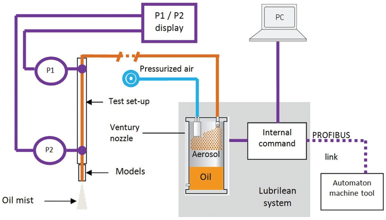
The experimental test rig illustration with its two pressure sensors, along with the mist generator supported by a PC.
Readings were taken at P2 as reference for the interpretation and validation of the results and as benchmarks for the numerical validation. Characterization of the oil mist was ensured by the measurement of particle sizes and velocities as well as of consumption (by laser granulometry, particle image velocity (PIV) and residual gravimetric methods, respectively) for different inlet conditions and different geometry models. 20
For oil with a density of 930 kg m−3 and a dynamic viscosity of 80 mm2 s−1, the particle sizes were measured with a Malvern instrument device (laser granulometry process) and ranged between 1 µm < ∅ < 100 µm. The major particle size was ∅ 1 µm (80%) because of the high oil viscosity. Because of the small size of the particles, the mean outlet velocity was measured with the PIV process by analyzing the recording of successive positions of the particles with La Vision acquisition system. The images were taken with a charge-coupled device (CCD) digital camera at a spatial resolution of 1376 × 1040 pixels. The frames were analyzed with Davis 7.0 software. The consumption was measured by the gravimetric method for each inlet pressure. Absolute BBT50 pleated filters were fixed at the end of the models and were weighed before and after the tests (duration of 1 min) on an electronic set of scales (type Sartorius A 210 P, with a precision of 0.0001 g). Special attention has been respected by conditioning filters for 24 h in an air-conditioned environment, prior to the experiment, in order to have a controlled humidity level. As shown in previous work, 20 the oil amount has been kept constant in this numerical study and was set to 10 mL h−1 for the numerical study (Table 2). (The reader can refer to Duchosal et al. 20 for more experimental details.)
Air and oil flow rates as function of inlet pressure.
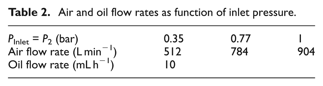
The inlet conditions were taken as inlet pressures from the external oil mist device. Three inlet pressures were considered as minimum, mean and maximum air/oil flow rate. Table 2 shows the different parameters used in this experimental study.
Finally, the test setup was designed to connect to different inner channel models that can be found on a cutting tool (Figure 3). These models simulated different ranges of geometry. Models can be found with straight ∅ 6 mm and bifurcations of 45° (Figure 3(b)) and 90° (Figure 3(c)) channels. These ranges of geometry show broadly what internal machine channels can generate in a tool body. The shape of the geometry creates pressure losses of ξ = 0.5 for a 45° channel and ξ = 1.3 for a 90° channel (with ξ being the loss coefficient). It is therefore essential to maintain a constant cross section of internal diameter to limit pressure losses.
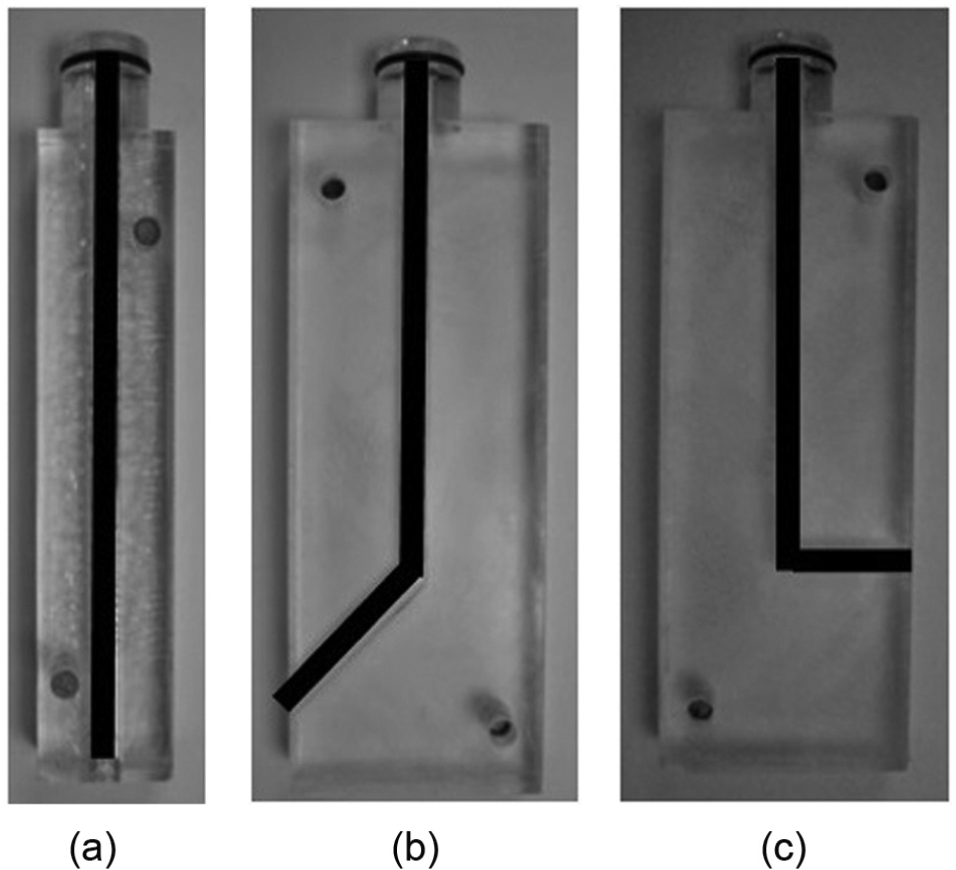
Illustration of the different models used: (a) straight ∅ 6 mm, (b) 45° and (c) 90° oriented channels.
Numerical/experimental validation
Numerical channels were set on standard channel geometries as in the experiments (Figure 3) with the same section (∅ 6 mm). Three channel models were taken into consideration: straight, 45° and 90° bifurcations over a wide pressure range (based on experimental data downstream from P2 (Figure 2), that is, Pinlet (Table 2).
The experimental output velocities obtained with the PIV process from the experimental stage (section “Experimental test rig”) were compared to the numerical velocities obtained by simulating the same process as experiments. The numerical output velocities were obtained with different inlet pressures from the pressure sensors used in the experiment, and Figure 4(a)–(c) shows comparisons between the numerical and experiment output velocities for different inlet pressures for straight, 45° and 90° channels, respectively.
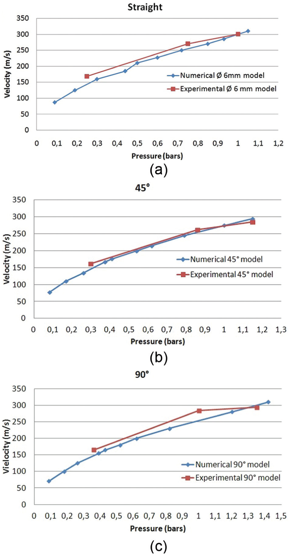
Experiment versus simulation correlation curves of the outlet average velocities for (a) ∅ 6 mm straight model, (b) ∅ 6 mm 45° bifurcation model and (c) ∅ 6 mm 90° bifurcation model.
As shown in Figure 4(a)–(c), the numerical models of the flow motion showed good agreement with the experimental average outlet velocities: errors were approximately 12%, 7% and 9%, respectively, for the different pressures. These results (Figure 4) indicated good agreement between measurements and simulations and confirmed the validity of the models. The experimental velocities were taken from the small particle velocities measured with the PIV process (about ∅ 1 µm). The numerical velocities were measured for the continuous phase (pressurized air). In the numerical static analysis, the velocity of small particles was the same as the velocity of the main flow. 23 The “one-way coupling” condition justified these same velocities. This correlation confirmed that the small particle size had no effect on the flow motion, and the velocities of the small particles were the same as the continuous phase.
Integration of milling tool rotation
The validated numerical models in static conditions were used in this section to simulate rotating channels. A numerical milling tool was taken as reference from a surface milling experiment. The prototype was made up of secondary channels connected to a central channel. The secondary channels were oriented at 45° in relation to the vertical axis and directed the oil mist to the cutting edges, as shown in Figure 5.
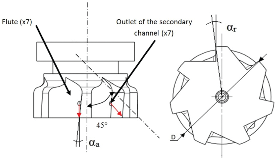
Illustration of a surface milling tool shape with inner secondary channels (oriented at 45°, here), on the left (bottom view on the right). Oil mist spray is shown by the red arrow pointed at the cutting edge.
This surface milling is widely used in automotive industries for surfacing processes (engine blocks, cylinder heads). This tool model is the first milling tool equipped with internal channels for microlubrication transport. The external diameter is D = 80 mm, with seven carbide inserts, which are not represented for this study. For this type of tool, the flutes are deeper compared to traditional tool ones to facilitate chip removal, with rake angle αa and radial rake angle αr (Figure 5).
The microlubrication of each carbide insert was ensured by each secondary channel turned toward the cutting edge, as shown by the red arrow in Figure 5. The sum of each seven channel sections was equal to the vertical central channel section to maintain the flow rate. 24 This unsteady motion problem was converted to a steady-state problem by imposing a moving frame of reference on a static mesh. A motion reference frame (MRF) was thus considered for all rotating parts in a static outlet condition. A cylindrical coordinate was attributed to the MRF which considered the different rotation velocities for the study. For the rotation of the reference frame, the rotational body force was considered which depended on the rotational velocity. The rotational body force was integrated in the momentum equation of the particle phase.
This section dealt with the behavior of the oil particles outside the channel, in particular the ability of the oil particles to reach the cutting edge. The efficiency of the spray depended on several parameters: (1) inlet pressure, that is, the input effect; (2) the rotation speed and (3) the external configurations, that is, the output effects. The external milling shape and the machining configurations were included in this latter parameter.
Boundary conditions
Because of its wide range of applications, two rotation speeds (5000 and 20,000 r min−1) and two inlet pressures (minimum and maximum at 0.35 and 1 bar) were studied. These values were close to the inlet pressure values from the experimental results for straight ∅ 6 mm and 45° models. The outlet conditions were taken as ambient air with two output configurations. The first consisted of rotating the milling tool without nearby workpiece. The other was in the context of a surfacing process and the milling tool was close to a workpiece (about 1 cm).
Finally, particle flow was considered to study the particle effect on the cutting edge: ∅ 1 µm particle size was used for all simulations. As explained in section “Experimental test rig,” the majority of the present particles have ∅ 1 µm diameter (80%). Moreover, the high pressurized air governs the oil mist behavior, and the fraction of the ∅ 100 µm particles has no effect on the main flux of the oil mist and follows precisely the flow motion as the particles of ∅ 1 µm diameter. An average consumption of 10 mL h−1 is considered in order to be in the same experimental conditions
Effects of inlet pressure
In order to overcome the aerodynamic effects, this part considers the influence of the inlet pressure. The P2 values measured downstream from the experimental test rig were considered to be inlet pressures of 0.35 and 1 bar. The minimum and maximum inlet pressure values were thus simulated for the numerical prototype, with no nearby workpiece, as shown in Figures 6 and 7, respectively. The MQL spray efficiency is based on the oil mist behavior, defined by streamlines, and its capability to reach the cutting edge, shown in Figure 5.
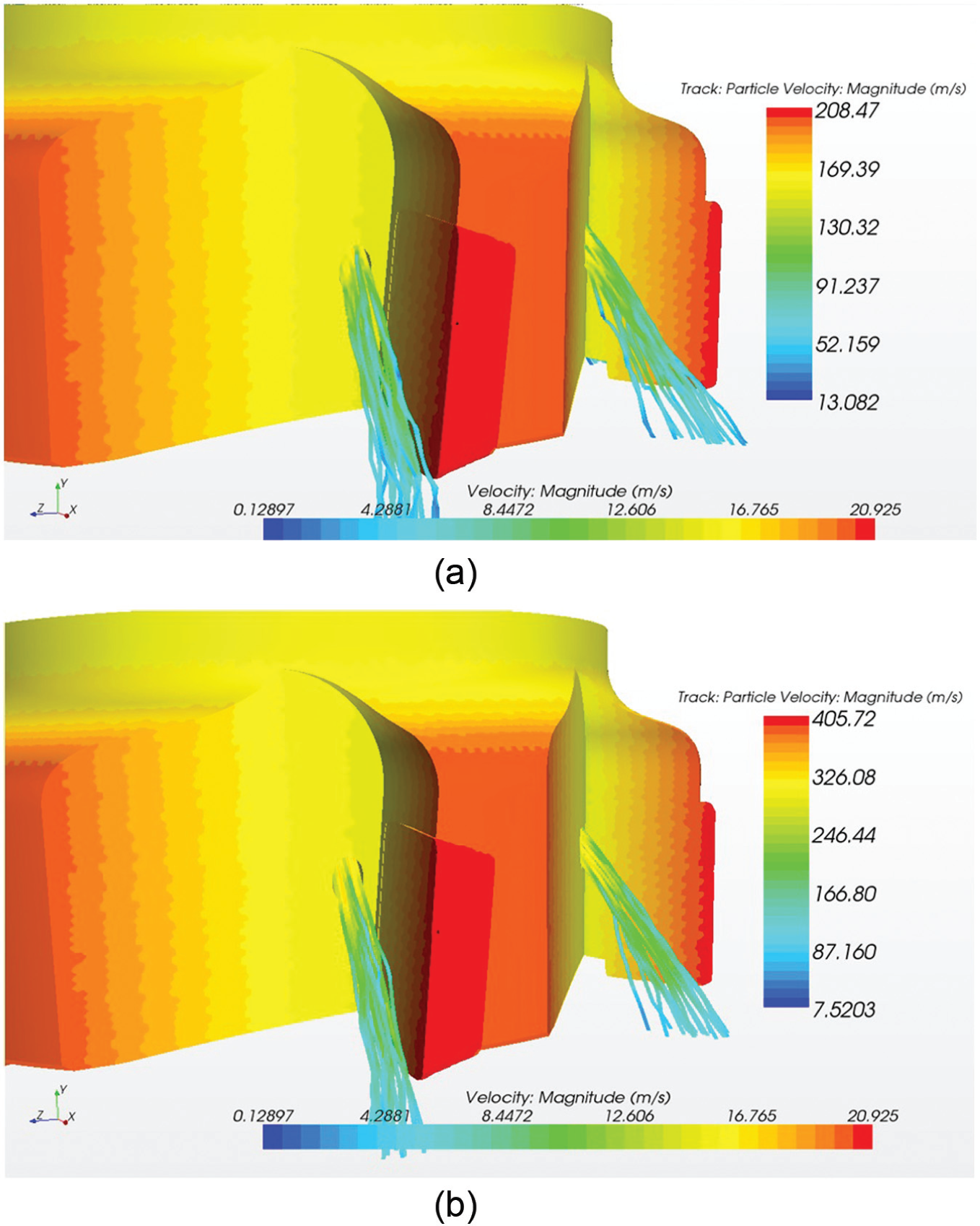
Illustrations of the particle behavior outside the channels for (a) 0.35 bar and (b) 1 bar input pressures at 5000 r min−1.
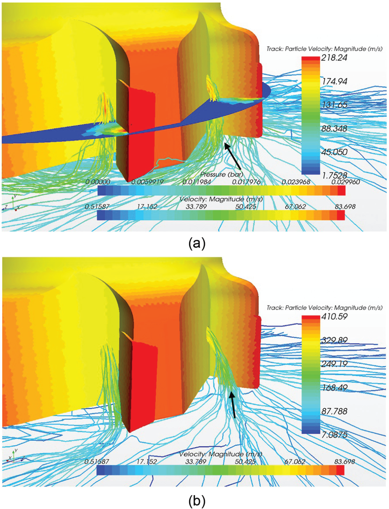
Illustrations of the particle behavior outside the channels for (a) 0.35 bar and (b) 1 bar input pressures at 20,000 r min−1.
Figure 6(a) and (b) illustrates the behavior of the particles at 0.35 and 1 bar input pressure, respectively, for 5000 r min−1. For 0.35 bar input pressure (Figure 6(a)), the oil mist went straight out of the channels at about 150 m s−1. The particles rebounded and spread over the lower middle side of the carbide inserts. No particular change was noted for the stronger inlet pressure (1 bar), as shown in Figure 6(b). The average outlet velocity was about 333 m s−1. At a low rotation speed (5000 r min−1), there was no particular aerodynamic effect on particle flow outside the channels. Whatever the inlet pressure and hence the output velocity, particles had the same spray behavior. In this case, it would be preferable to choose 0.35 bar inlet pressure which uses less energy.
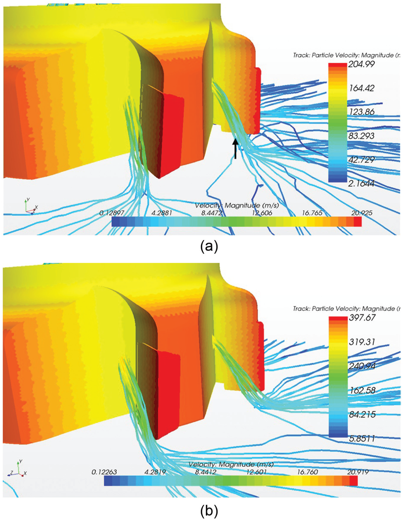
Figure 7(a) and (b) illustrates the behavior of the particles for the same input pressures as above (0.35 and 1 bar, respectively) at 20,000 r min−1. Because of the high rotation speed and the low inlet pressure (Figure 7(a)), the oil mist did not have enough velocity to spray the carbide inserts. The oil particles then stuck on the tool body due to the rotation speed and its particular shape. The high rotation speed caused high pressure in front of the carbide insert (0.02 bar in front of the carbide insert) influencing the oil mist behavior, as shown in Figure 7(a). For high inlet pressure (1 bar), the oil particles were sprayed on the carbide inserts but only on half of the cutting edge (Figure 7(b)). The average velocities were about 180 and 340 m s−1, for 0.35 and 1 bar, respectively.
Effects of nearby workpiece
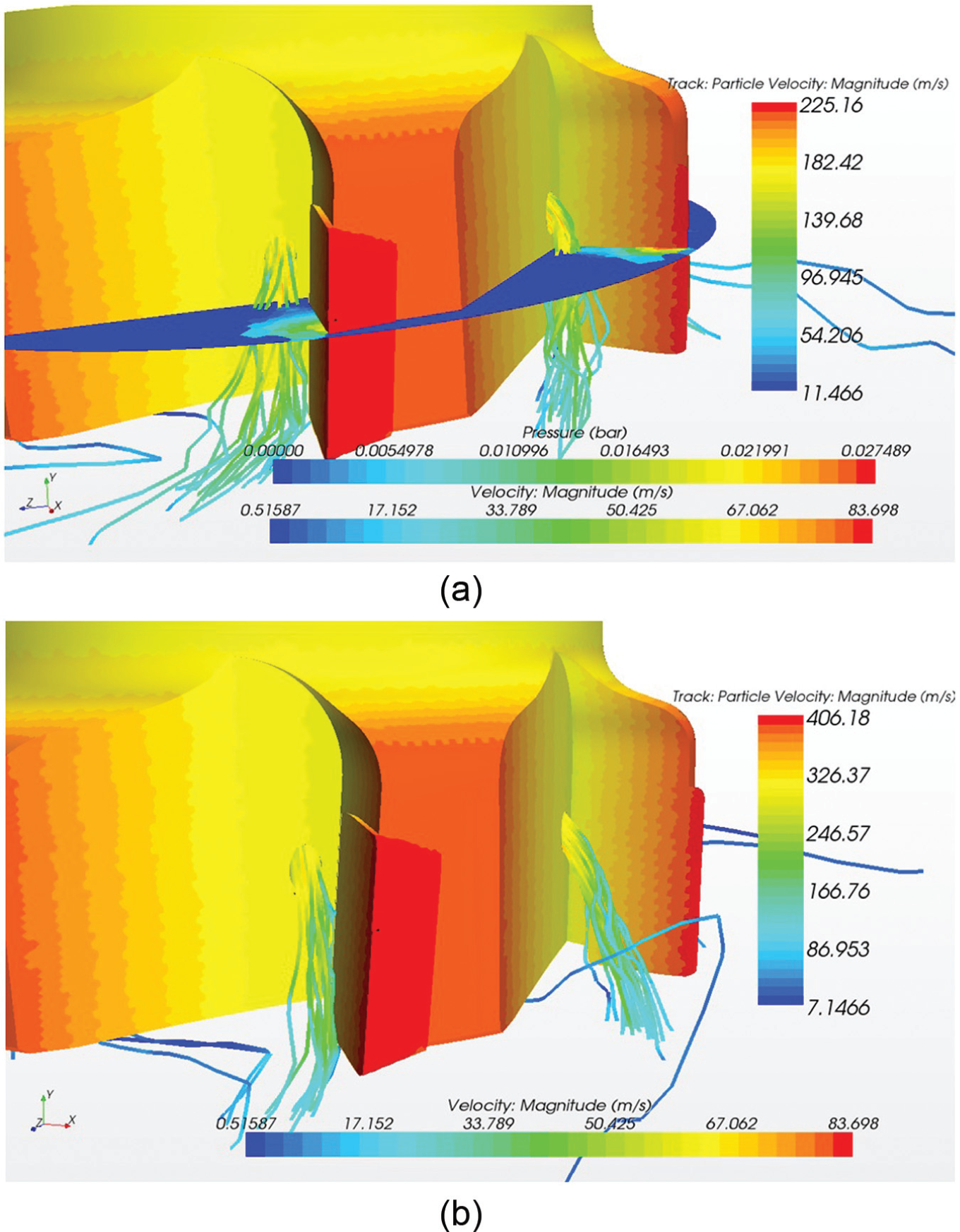
In this section, a nearby workpiece was considered as a wall effect and placed immediately under the milling tool (less than 1 cm). Figure 8(a) and (b) illustrates the behavior of the particles outside the channel of the prototype close to a workpiece at 5000 r min−1. For the 0.35 bar inlet pressure (Figure 8(a)), the oil mist went out of the channel and sprayed on the carbide inserts but halfway along the cutting edge (black arrow, Figure 8(a)). The strong inlet pressure of 1 bar improved the oil mist spray on the inserts (Figure 8(b)). The oil particles rebounded on the lower middle side of the carbide inserts and finally spread over the workpiece. Similar outlet average velocities were noted as seen on the top in Figure 6 (i.e.160 and 310 m s−1 for 0.35 and 1 bar, respectively).
Illustrations of the particle behavior outside the channels for (a) 0.35 bar and (b) 1 bar input pressures at 5000 r min−1, close to a workpiece.
Figure 9(a) and (b) illustrates the behavior of the particles for the same input pressures as above (0.35 and 1 bar, respectively) at 20,000 r min−1. The phenomena were clearly the same as above with no workpiece. High pressure occurred in front of the carbide inserts, avoiding the oil mist spray. The oil mist then stuck to the tool body (black arrow, Figure 9(a)). This phenomenon also occurred at 1 bar inlet pressure, as shown in Figure 9(b). The trajectory of the particles was slightly deflected, and the particles were sprayed on the beginning of the carbide insert (black arrow, Figure 9(b)).
Illustrations of the particle behavior outside the channels for (a) 0.35 bar and (b) 1 bar input pressures at 20,000 r min−1, close to a workpiece.
Discussion
The oil mist behavior was not affected by the position of the workpiece, as shown in the simulations. The average outlet velocities were very close for the same rotation velocity and inlet pressure (e.g. at 5000 r min−1 and 0.35 bar, the velocities were 150 and 160 m s−1, respectively, in Figures 6(a) and 8(a)). It means that the tool shape combined with the rotation velocity governs the oil mist behavior outside the secondary channels.
Because of its particular shape and its range of use (5000–20,000 r min−1), the wind engagement is particularly important, creating small pressure on the carbide insert (as shown in Figures 7(a) and 9(a)). Basically, the rotation of the milling tool produces aerodynamic effects (as a fan) because of the flutes. Moreover, the distance between the outlet of the secondary channels and the cutting edge influences the spray efficiency. Outside the secondary channels, the oil mist spray on the cutting edge is based on the contributions of the aerodynamic phenomena. These two parameters affected the efficiency of the lubricant. From these observations, it is clear that the milling tool shape combined with the machining configurations induces phenomena which influence the oil mist spray on the cutting edge.
For the same inlet pressure, the rotation velocity increased the average outlet velocity of the oil mist (e.g. 150 and 180 m s−1, respectively; Figures 6(a) and 7(a)). Thus, it is very important to keep small particle sizes with negligible inertia to avoid particle impingement on inner channels. Large particles are spread on the wall channels and are reconditioned in the main pressurized air flux. The reconditioned oil leads to poor spray efficiency by sputtering effect outside the secondary channels, as shown in previous work. 23 These large particles are sprayed outside the channels with strong inertia, based on the rotation velocity and spread at the same altitude as the outlet of the secondary channels on the carbide insert.
In parallel, high inlet pressure has to be considered to overcome the aerodynamic phenomena due to the shape and the rotation velocity. Indeed, high inlet pressure helped the oil mist to reach the cutting edge, as illustrated in Figure 7(a) and (b). But the oil mist did not spray specifically on the cutting edge, whatever the rotation speed. The cutting edge could be lubricated with the displacement of the formed film liquid after few seconds of rotation. High pressure level is not the solution because the risk of particle impingements inside the canalizations grows and leads to increase sputtering effect. Other parameters such as the orientation of the inner geometries must be taken into account to enable the oil mist to spray on the cutting edges at any rotation velocities.
Conclusion
In this article, the flow of the oil mist particles used in a lubricating machining process (MQL) is studied. The main goal was to study the effects of inlet pressures on the oil mist flow behavior outside the channels of the tool body according to different parameters (rotation speed and machining configuration).
First, different channel geometries were studied with different boundary conditions to validate the RANS numerical model. The concordance of the results from the numerical and the experimental outlet velocities has been established and validated for the flow model.
Second, the validation made it possible to consider dynamic simulations such as the rotation of a milling tool. The conclusions of this study were as follows:
Increasing the rotation speed increased the velocity of the oil particles which highlighted the need of keeping small particle sizes.
Increasing the rotation speed created high pressure in front of the carbide inserts with the result that the oil mist tended to stick to the tool body.
Increasing inlet pressure increased the oil mist velocity and improved spraying on the carbide insert.
The position of the workpiece had a minor influence but tended to increase the velocity of the oil particles.
As shown in this study, there were no ideal configurations to provide an effective spray. Due to the particular shape of the milling tool, the best configurations were at low rotation speed (5000 r min−1) and the worst were at high rotation speed (20,000 r min−1) and low inlet pressure (0.35 bar). As expected, the geometries of the internal channels have to be taken into consideration, in particular the orientation of the secondary channels which supply the carbide inserts with the oil mist. Particle inertia should therefore be considered, and thereafter several orientations of channels as a function of different input (inlet pressures) and output (rotation speeds and differently oriented channels) configurations in future studies.
Footnotes
Declaration of conflicting interests
The authors declare that there is no conflict of interest.
Funding
This research received no specific grant from any funding agency in the public, commercial or not-for-profit sectors.