
Abstract
High-speed machining, the need to reduce environmental impact and manufacturing cycle time have promoted the use of minimum quantity lubricant in mechanical machining. However, in minimum quantity lubricant, where a small quantity of cooling lubricant is delivered to the cutting zone, the sensitivity of machining performance to nozzle position has hardly been explored in research or noted in industrial practice. In this study of conventional versus high-speed machining, the focus was on a systematic study of the effect of nozzle position on tool wear. This study elucidates the effect of spindle rotation speed on the sensitivity of nozzle location in order to enhance machining performance. This work provides some fundamental information regarding the position and orientation of the nozzle in order to maximise the benefits of machining using minimum quantity lubricants. This work is of significant importance for the repeatability of minimum quantity lubricant machining operations and to promote longer tool life in particular for machine shops where nozzles are currently randomly oriented to the cutting zone.
Introduction
Historically, machine shops have predominantly employed cutting fluids. As coolant and lubricant, cutting fluid improves machining process performance. Cutting fluids play a significant role in reducing cutting temperature and lowering friction on the interfacial surfaces of a cutting process system (e.g. tool–workpiece interface and tool–chip interface). These surfaces generate heat. Coolant and lubricant cutting fluids contribute to prolonging tool life, obtaining better surface finish and minimising the geometrical error in machined parts. In addition, when cutting fluid is delivered to the cutting zone at high volume and high pressure, it helps to flush chips from the cutting zone. This reduces re-machining of strain-hardened chips and promotes better machining performance.
The superior advantages gained using cutting fluid have induced uncontrolled use in delivery and the use of copious amounts of fluid. However, the need to reduce thermal shock, the rise in environmental concerns, also linked to the impact of cutting fluid usage on the environment, as well as strict regulation for disposal of cutting fluid waste by a number of industrialised countries have attracted interest in the development of machining processes that avoid the use of cutting fluids. 1 –3 Alternative strategies are dry machining and near-dry machining. Full implementation of dry machining is limited by the need to reduce friction and thermal load. 4 Development of coating materials and a shift to near-dry machining technology bridge the gap while an alternative method to flood coolants is developed. One of the most promising near-dry machining methods is minimum quantity lubrication (MQL). In MQL, the volume of cutting fluid delivered to the contact zone can be significantly reduced to 1 mL/h. 5
In flood coolant applications, large volumes of cutting fluid are delivered around the machining area; therefore, the possibility of cutting fluid penetrating all the critical interfaces is high. As such, the direction of the nozzle is usually not critical. However, in one study, Diniz and Micaroni 1 found that when using high-pressure and high-flow rates, positioning the nozzle towards both flank face and rake face simultaneously was beneficial for prolonging tool life in comparison with directing the nozzle towards only one of the faces. Later, Rahman et al. 2 postulated the importance of nozzle position for improving MQL performance.
MQL supply parameters
The ultimate goal of using cooling/lubricating media in a machining process is to reduce cutting temperature and friction as much as possible. This becomes the greatest challenge in respect of the MQL method due to the restricted amount of cutting fluid delivered during the cutting operation. Ueda et al. 6 measured the tool temperature in end milling using a two-colour pyrometer embedded in annealed AISI 1045 steel workpiece material. Two nozzles were used to cool down the workpiece–tool contact area. The nozzles were located at 45° angle (e.g. position B) and 135° angle (e.g. position A) and positioned 50 mm away from the contact point of tool and workpiece material (Figure 1).
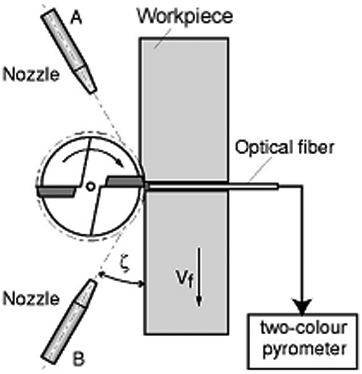
Nozzle position in end milling. 6
The result showed that locating the nozzle at position A gave a temperature value of 50 °C lower than locating the nozzle at position B. They assumed that at position A, a large amount of oil droplets adhered to the tool face during the cutting process act as a coolant. While in position B, some of droplets may blow away from the cutting point and decrease the percentage of oil droplets acting as a coolant at the cutting point. Other plausible explanations for the lower cutting temperature when the nozzle is in position A are that in this position, the tool has undergone a significant temperature reduction before entering the engagement point, and this condition could help the oil droplets to provide effective cooling. Meanwhile, in position B, the tool is still experiencing higher temperatures. Oil droplets delivered are only able to reduce the tool temperature when the tool actually enters the engagement point. Taking into account the direction of the tool rotation, Figure 1 shows that position B is the tool exit position. Thus, their work suggested that nozzles should not be located close to the chip evacuation path.
Sasahara et al. 7 came to a different conclusion about the effect of the nozzle position in high-speed cutting of S45C material. They found that spraying the cutting fluid at the exit point (disengagement point) resulted in the longest tool life due to elimination of chip adhesion. Yuan et al. 8 evaluated the effect of the nozzle position in an end milling process of 50CrMnMo, a structured alloy steel. The position of 60° away from the disengagement point led to prolonged tool life. Meanwhile, a modelling approach to evaluate tool wear in near-dry turning suggested that the nozzle should be directed onto the rake face to give the longest tool life for cutting high-strength low alloys. 9 In contrast, it was suggested that the nozzle position could be ignored when cutting Ti-6Al-4V material since no significant variation in cutting force and cutting temperature was experienced by changing the position of the nozzle. 10
Referring to previous findings described above, it seems that there are some conflicting recommendations regarding nozzle location. One study suggested positioning the nozzle at the tool disengagement point (exit point); however, it could be argued that this zone should be free of interference, as MQL pressure would hinder chip evacuation. This area is where the chip evacuates, and chip removal is critical for MQL process effectiveness. López de Lacalle et al. 11 simulated the spraying effect of cutting fluid using computational fluid dynamics (CFD) software and concluded that the nozzle should be located before the tool engages the workpiece material to ensure the MQL jet reaches the tool edge. The location of the nozzle has to balance the need for effective MQL fluid delivery (fluid trapping), the requirement not to retard chip evacuation and the effect of MQL application on the thermal regime and safety considerations.
Research motivation
When minimum quantity cutting fluids are used, the delivery of the fluid and, hence, the position of the nozzle are important, 2,3 in order to maximise the benefits derived from limiting the volume of cutting fluid. There was no consensus in the literature regarding the optimum position for MQL nozzles. Neither was there significant awareness that this is a key process variable (KPV) in industrial machining. The motivation for this work was to determine the effect of nozzle position in high-speed milling of tool steel in order to maximise the benefits of using MQL.
Research method
Cutting tests were performed on a Mikron HSM 400 high-speed milling machine to evaluate the best location for the MQL nozzle. The material used in this study was a 150 mm × 100 mm × 100 mm block of H13 tool steel. Initially, cutting tests were conducted on the workpiece material in its ‘as-delivered’ state, and in this condition, the hardness was measured to be 13 HRc. The second test was performed on the material after the hardness had been increased to 45 HRc achieved by vacuum heat treatment. The cutting inserts were physical vapour deposition (PVD) TiAlN coated supplied by ISCAR with code name IC928. The geometry for the inserts was SOMT060204-HQ. The inserts were mounted on an ISCAR 8-mm-diameter tool holder E90XD08-C10-06. This tool holder accommodates only one insert. This was specifically selected in order to study the process in single-tooth cutting mode. The cutting speed was varied from 350 to 700 m/min, following the manufacturer’s recommendations for the type of inserts used in this experiment. This range of cutting speed spanned the transition to the high cutting speed region as defined by Schulz and Moriwaki. 12 The feed per tooth (fz) and axial depth of cut (ap) were kept constant at 0.05 mm/min and 1.5 mm, respectively. A width of cut of 4 mm for the ‘as-received’ workpiece condition was used, and this was reduced to 0.6 mm for the harder workpiece to take into account the greater machinability challenge. The selected feed per tooth and depth of cut were considered in order to minimise tool wear rate especially when the cutting speed is increased to high speed. In addition, the low chip load avoids higher cutting forces. 13
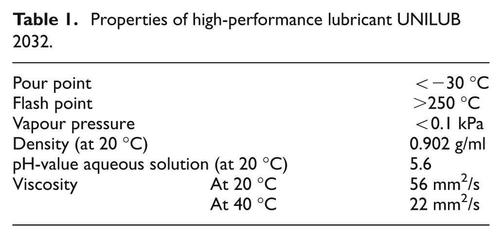
For the end milling of the H13 workpiece material using the MQL application, 29.9 mL/h of high-performance lubricant UNILUB 2032 (lubricant properties are specified in Table 1) was delivered to the cutting interface using a pressure of 4 bar (e.g. maximum operating pressure for MQL system used in this study is 8 bar). The quantity of cutting fluid delivered was verified by collecting the delivered fluid in a container for a monitored duration. The 29.9 mL/h flow rate used was the highest possible on the machine, and this value was found to be the best in terms of tool wear performance based on a prior Taguchi process optimisation. 14 End milling was performed twice for every experimental run.
Properties of high-performance lubricant UNILUB 2032.
In this study, the nozzle was held in a constant position of 60° to the spindle and tool axes, as shown in Figure 2(a). From the workpiece end-milled face and the tool entry point, the nozzle was located at 12.5°, 45° and 135°. The set of nozzle positions is illustrated in Figure 2(b). The nozzle discharge tip was positioned 4 mm away from the tool to avoid increasing the spraying angle that can lower the fluid particle pressure, hence minimising effective application of MQL. 15 A longer distance also promotes excess mist. 16 The nozzles were aligned in these positions to enable the assessment of the fluid trapping effect and the need to avoid obstruction of chip evacuation by the MQL jet.
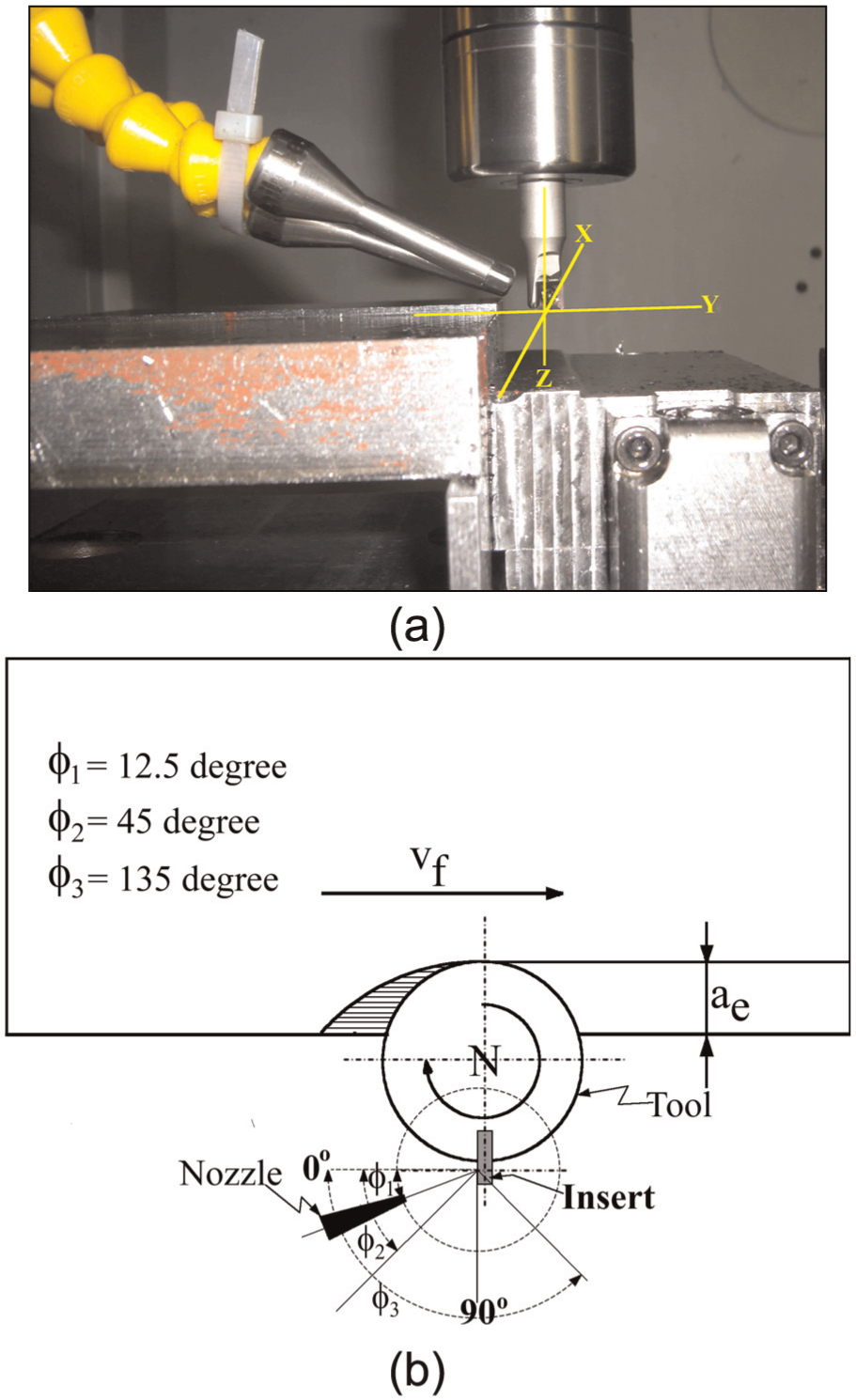
(a) Nozzle position relative to spindle axis and (b) nozzle position relative to tool entry position and workpiece end-milled face.
In this study, the nozzle was not located towards the exit side or tool disengagement point. The highest temperature of the tool was reported to be at the tool exit point, 17,18 and avoiding this point helps to reduce the chances of the tool experiencing thermal shock and cracking, 19 and it also ensures that the fluid flow does not hinder chip evacuation. Additionally, at the tool engagement point, it is difficult to maximise the fluid trapping as fluid is carried away by the rotational force.
A Leica optical microscope was utilised for taking images of the tool clearance face and flank wear. Average tool wear was measured for two experimental runs for each text condition. This was done using AxioVision Rel. 4.8 image-processing software. In evaluating the tool life, the tool wear criterion was set at 0.3 mm of average flank wear. 20 Meanwhile, a Hitachi Scanning Electron Microscope S-3400N was utilised for capturing the details of the condition of flank and rake faces.
Results and discussions
Nozzle position impact on tool wear and tool life H13 steel in annealed state
Figure 3 shows the tool wear and tool life as a function of nozzle location for a spindle speed of 13,934 r/min (i.e. equal to a cutting velocity of 350 m/min). The nozzle was located at three different positions of 12.5°, 45° and 135° from the tool–workpiece initial engagement side. The results show that when 135° was used, flank wear increased faster than when the other smaller angles were used. This is particularly evident from 16 to 27 min of cutting time. In principle, the closer the nozzle is located to the sidewall of the workpiece material, the better the tool performance in terms of tool wear. When the MQL fluid is applied to the surface of a cutting tool, it follows the momentum of the tool. Aligning the nozzle closer to the entry point of the cutting tool helps trap the fluid, thus providing the lubricating action. Figure 3 also shows that the location of the nozzle is more critical in extended periods of cutting, when the tool has experienced advanced wear and its cutting effectiveness is reduced. This is evident from data points diverging at longer cutting times.
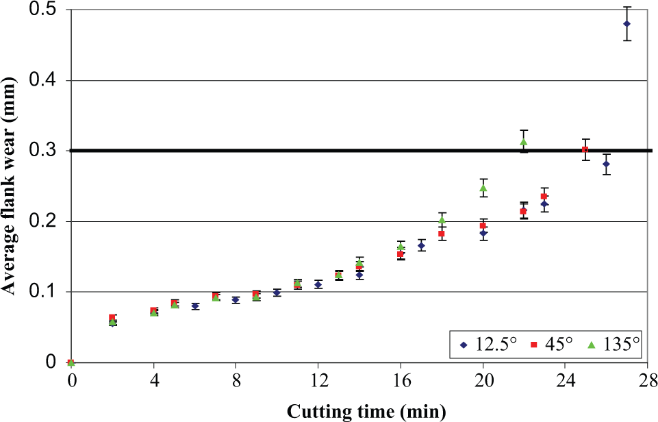
Nozzle position and tool wear progression under MQL application at 13,934 r/min.
Effect of nozzle position when machining hardened H13 workpiece material
The study described in the previous section showed that when machining annealed tool steel, the nozzle should be positioned towards the rake face and closest to the workpiece sidewall at the tool entry position. A follow-on study was done based on hardened tool steel and assessing the 12.5° and 45° positions, which had given better and comparable tool wear performance when machining the as-received tool steel. The 135° having shown a higher wear rate was not pursued. In many applications, such as dies and moulds, the tool steel workpiece is in a hardened state. Hot-work steel is extremely tough and has the ability to withstand wear and cracking. Hardening this type of tool steel can result in more challenging machinability. Figure 4 shows the tool wear progression in respect of the two nozzle alignment angles when machining hardened tool steel.
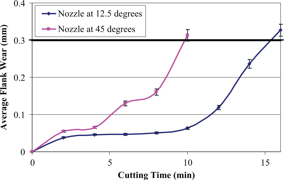
Effect of nozzle positions in end milling of hardened H13 tool steel at 13,934 r/min.
When Figure 4 is compared to Figure 3, the reduction in tool wear rate and tool life due to the increased hardness of the workpiece material is evident. When the material was hardened to almost four times its annealed state (from 13 to 45 HRc), positioning the nozzle closer to the workpiece face at an angle of 12.5° significantly improved tool life in comparison to orienting the nozzle at an angle of 45°. Thus, simply shifting the nozzle from a 45° angle to a 12.5° angle at the end-milled face leads to a massive 55% increase in tool life. When machining hardened steel, the temperature is quite high, and in this case, the nozzle position appears to be very critical and a dominant KPV has to be controlled. This is a step change in the knowledge of process behaviour, as the nozzle position is rarely considered critical in machining.
In order to explore why the 12.5° angle prolonged tool life performance in comparison to an angle of 45°, an analysis using scanning electron microscopy (SEM) was conducted. The flank face and rake face were examined, and these images are shown in Figures 5 and 6, respectively. Figure 5 reveals that with the nozzle angled at 12.5°, flank wear had a uniform pattern along the depth of cut line; when the nozzle was angled at 45°, the pattern was irregular and became enlarged close to the end of the depth of the cut line. In addition, in Figure 5(b), a sharp notch is distinct at the flank face of the cutting tool for MQL with the nozzles at a 45° angle. The images show that locating the nozzle closer to the workpiece appears to result in uniform tool wear. This could suggest improvements in lubrication and/or cooling effect.
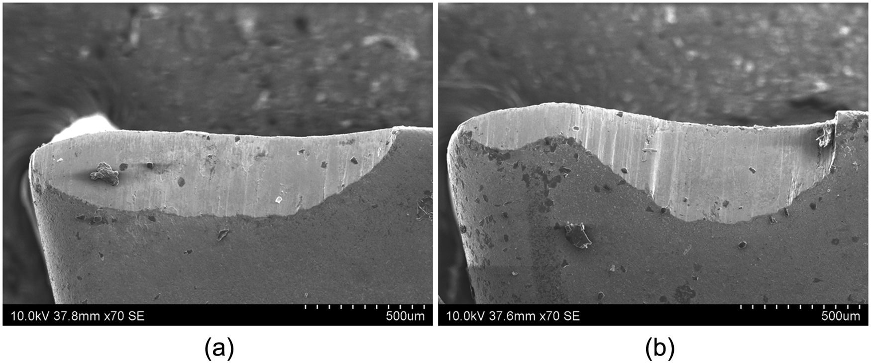
SEM images of flank face after cutting exposed by cutting fluid from nozzle at positions of (a) 12.5° and (b) 45°.
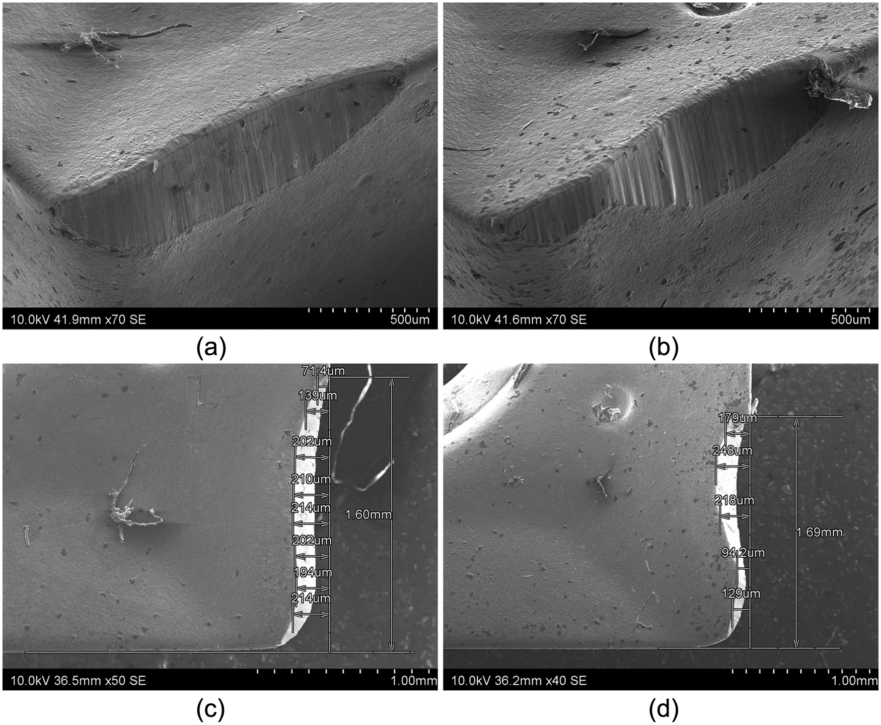
SEM images of TiAlN insert after machining after MQL delivered from different positions: (a) 3D insert image for insert used at 12.5°, (b) 3D insert image for 45°, (c) image of the rake face for 12.5° and (d) image of the rake face for 45°.
Closer observation of the rake face, as depicted in Figure 6, shows that the lower the angle of the nozzle, the more uniform the tool wears. For machining harder tool steel workpiece material, a more effective supply of lubricants is required.
Assessment of fluid trapping at different nozzle positions
The effect of the rotation of the tool on fluid trapping was investigated using the method illustrated in Figure 7. This involves the use of a fluid soaking device (sponge) to assess the quantity of cutting fluid delivered to a particular location. In this method, the volume of droplets trapped in sponge 1 (representing the sidewall of machined workpiece material) and sponge 2 (parallel to the feed direction) was quantified. The distance from outer diameter of the rotating tool to both sponges was kept constant at 4 mm and similar to the cutting tests. This offset was useful to make sure that the tool would not cut or push the sponge.
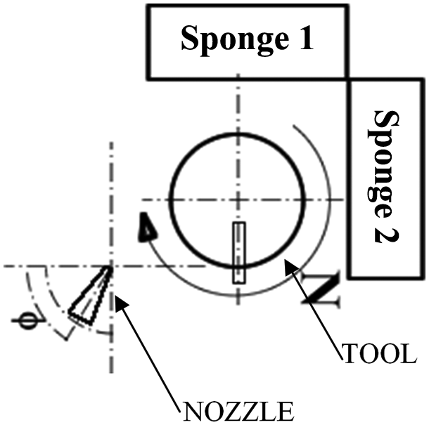
Method for quantifying MQL fluid trapping.
Initially, the weight of the sponges was recorded, and then the spindle was run at selected revolutions per minute with the nozzle directed to different orientations. The quantity of fluid collected by the sponge was evaluated from the measured mass of the fluid soaked sponge minus the dry sponge. The weight measurement for the sponges was done using a weight balance that had an accuracy of 1 mg.
The fluid trapped in the sponges at both directions was measured after running the MQL nozzle flow for 30 min. Figure 8 shows the fluid trapped for different positions when running the spindle at 13,934 r/min. For each set, the experiment was conducted twice, and there was very little variation between the repeats, as shown in the range bars in Figure 8.
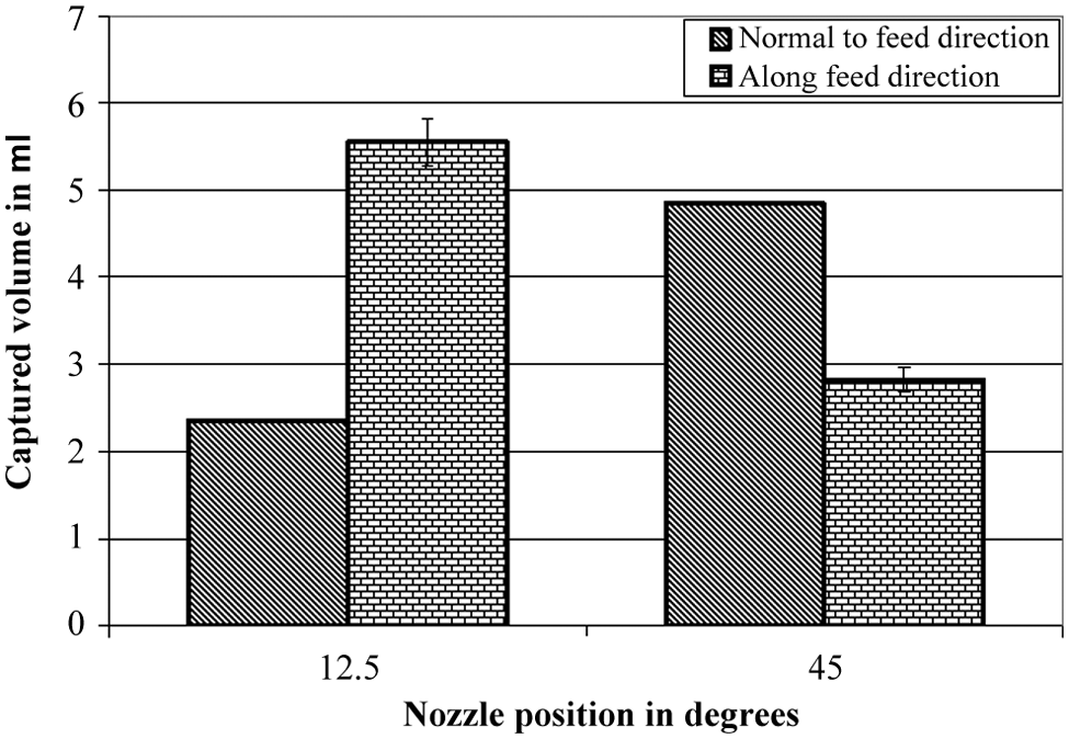
Effect of different nozzle positions on the possibility of fluid trapping using a rotational speed of 13,934 r/min.
From Figure 8, it is clear that by positioning the nozzle at an angle of 12.5° relative to the feed direction, there is more possibility that the rake face will receive more lubrication rather than when the nozzle is positioned at a 45° angle while using a rotational speed of 13,934 r/min. This is intuitively reasonable because at the lower angle to the entry position, more fluid is directed onto the tool engagement point, thus increasing the chance of MQL effectiveness. Thus, better fluid trapping supports improved tool life performance at 13,934 r/min when using a 12.5° angle orientation of the nozzle from the entry point and cutting plane. This can increase the effectiveness of the cutting fluid.
Effect of rotational speed on nozzle position of hardened H13 material
High rotational speed was identified as a key factor that influences the performance of the MQL application. 21,22 Figure 9 shows the effect of increased rotational speed to 27,867 r/min on tool wear progression. In this study, the nozzle was located at an angle of 12.5° towards the rake face, close to the end-milled face and tool entry position. This position was most suitable for providing the longest tool life at a rotational speed of 13,934 r/min according to the previous results. As can be seen in Figure 9, flank wear is rapidly increased after 2.8 m into the cutting length when high rotational speed was used (i.e. at a cutting speed of 700 m/min). The results illustrate the difficulty of introducing cutting fluid to provide a lubricating action when the spindle is operated at high frequency. Additionally, a higher cutting speed would lead to higher cutting temperatures, and this can activate and/or accelerate wear modes.
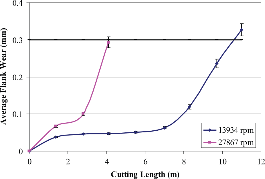
Effect of rotational speed on tool wear progression using a 12.5° nozzle orientation.
In order to explore process improvement, the nozzle was realigned in four different positions located further away from the engagement point: 25°, 35°, 45° and 60°. The average tool life for these new measurements can be seen in Figure 10. Employing the nozzle position at 45° achieved a tool life of approximately 5.7 min, which is higher compared to the other positions (i.e. 12.5°, 25°, 35° and 60°). These other positions attained tool life of 2.9, 3.8, 4.7 and 2.3 min, respectively. This improved result can be partly explained by the wiping effect being a dominant mechanism for transporting lubrication to the rake face. In addition, the wiping effect was supported by the appropriate penetrating angle for fluid delivery, which in turn can guarantee fluid particle trapping on the rake face. This theory was explored using a similar method as described in section ‘Assessment of fluid trapping at different nozzle positions’. The results are shown in Figure 11, where the angle of 45° resulted in the largest amount of fluid trapped.
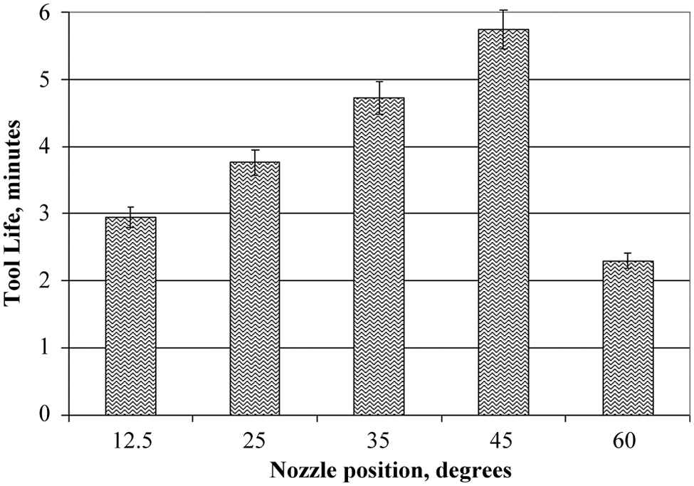
Tool life using different nozzle positions at a rate of 27,866 r/min.
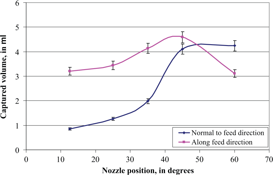
Effect of different nozzle positions on the possibility of fluid trapping using rotational speed of 27,868 r/min.
The results shown in Figure 11 support the results shown in Figure 10. The quantity of MQL delivered to the cutting zone is important. In milling, the spindle frequency is high and fluid is delivered over a shorter time window according to the nozzle orientation. Increasing the nozzle angle compensates for the reduced trapping time and reduced trapped volume that is experienced at higher revolutions per minute. This strategy is only valid at acute angles where trapping is effective. This explains why 60° is worse compared to 40° and 12.5°, 25° and 35° are worse compared to 45° at higher revolutions per minute, as shown in Figure 10. The tool wear results in Figures 4 and 10 agree and are supported by the fluid trapping data in Figures 8 and 11.
In addition, interesting characteristics in Figure 12 were observed from the morphology of the chips produced by end milling using nozzles at positions of 35°, 45° and 60°. At nozzle positions of 35° and 60°, end milling produces segmented chips compared to at position of 45° where the optimum tool life was achieved. The cases where segmentation occurred could be linked to increasing chip–tool interface temperature due to high friction force generated on the tool rake face. 23 Thus, it is conceivable that effective lubricating action and better thermal control were obtained by aligning the nozzle at a position of 45°.
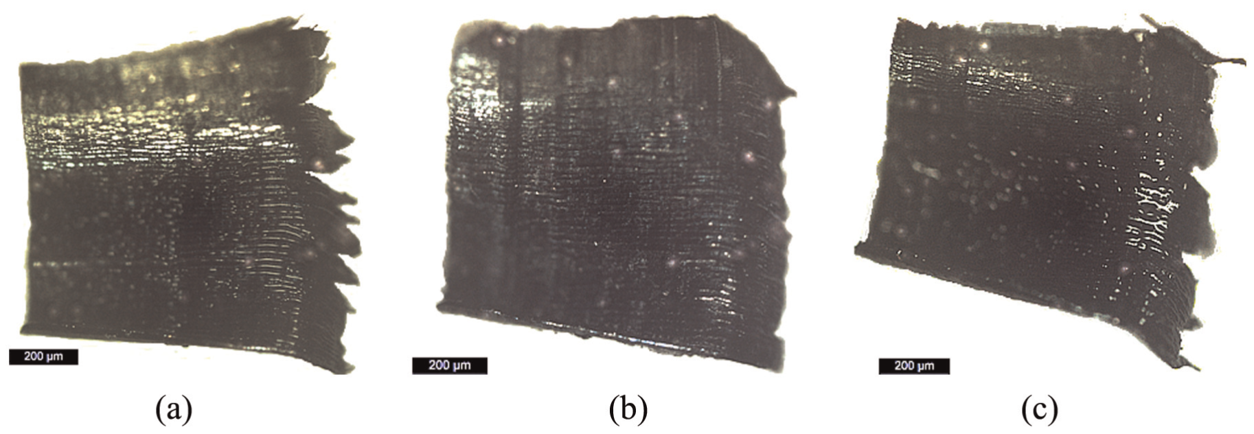
Image of the chip produced by end milling using nozzle at positions of (a) 35°, (b) 45° and (c) 60°.
To add further insight into the cutting tool’s performance at the highest cutting speed, microscopy analysis was undertaken on the inserts using SEM, and the observed images of the flank face and the rake face of the inserts are shown in Figure 13. Again, the best tool life performance is linked to uniform wear patterns, thus supporting effective lubricating action.
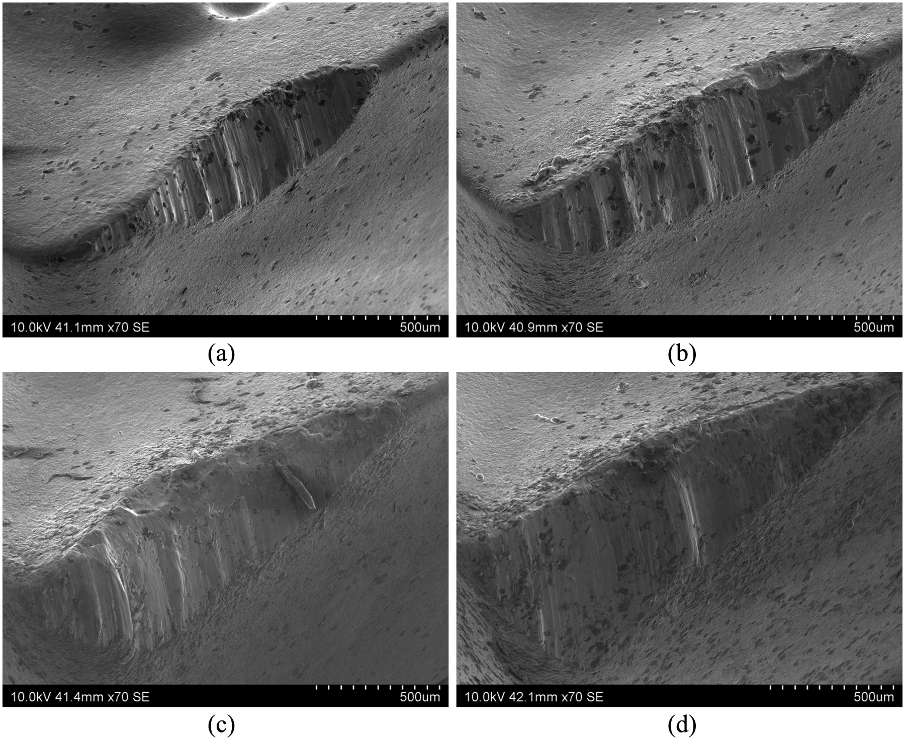
SEM images of flank face of the insert used for end milling with nozzle positions at (a) 12.5°, (b) 45°, (c) 35° and (d) 60° at 27,866 r/min.
Effect of increasing the fluid delivery pressure on tool wear progression
To observe the effect of increased fluid pressure at different nozzle orientations, a subsequent test was carried out where the fluid delivery pressure was increased to the maximum pressure (i.e. 8 bar). The tool wear progression using the higher pressure is plotted in Figure 14 alongside to that at 4 bar. From the graph, there is no strong evidence that increasing MQL pressure can significantly prolong tool life. Thus, changing the nozzle position is a more effective and more important strategy for increasing tool life than supplying MQL at higher pressure.
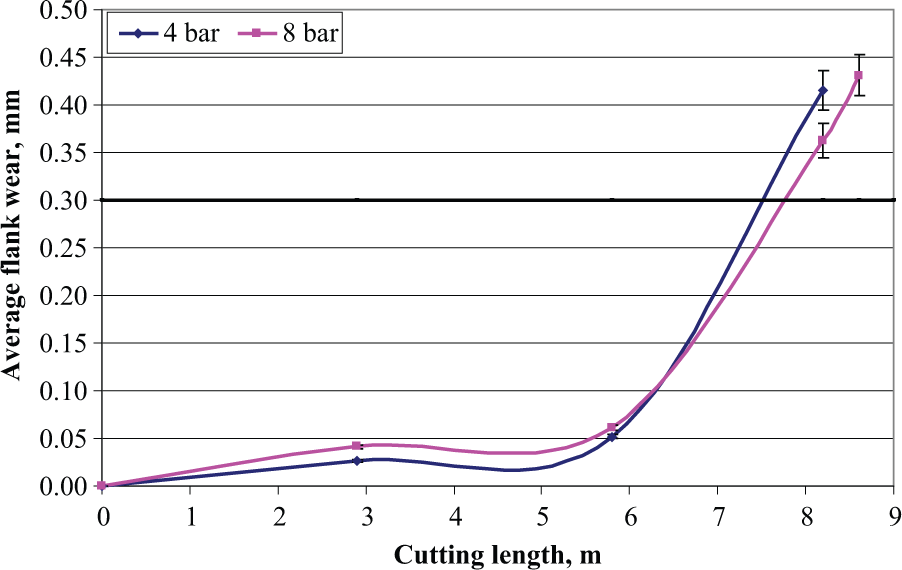
Effect of increased fluid delivery pressure on tool wear progression.
Conclusion
An investigation was conducted to study the effect of nozzle position on tool life in end milling of tool steel. This study yielded some important findings that could be transformative in improving the ability for controlling machining performance and improving the effectiveness of MQL in the machining processes:
In mechanical milling of tool steel in an annealed state, using MQL, there was some benefit for extending tool life by locating the nozzle closest to the end-milled face and tool entry point. This supports effective fluid delivery through a trapping action. For hardened tool steel (45 HRc), moving the nozzle from an angle of 45° back to an angle of 12.5° increased tool life by 50%. Thus, the position of the MQL nozzle is a critical process variable that needs to be controlled in end milling hardened tool steel.
The quantity of fluid collected by a soaking device aligned to the tool feed plane positively correlated with tool wear observations in MQL. Thus, to improve the effectiveness of MQL in machining, it is important to ensure that the maximum cutting fluid volumetric flux is delivered to the tool entry point and feed plane.
The wiping effect and penetrating angle are predominant factors in the effective delivery of MQL at high revolutions per minute. Positioning the nozzle at a 45° angle relative to the rake face and tool entry position doubled tool life compared to 12.5° and other positions (25°, 35° and 60°). Thus, when machining at high and ultra-high spindle speeds, the nozzle needs to be rotated away from the workpiece feed plane. This can deliver a high volume of fluid particles to compensate for the short tool–workpiece interaction time.
The optimum location of the nozzle, in relation to the rake face, correlates well with uniform flank wear land.
The nozzle position in MQL end milling of hardened tool steel at high spindle speeds is a critical consideration, which significantly affects tool life and machining performance. The nozzle should not be randomly fixed.
Footnotes
Acknowledgements
We would like to thank ASME publisher as well as Professor Takeshi Ueda, Professor Akira Hosokawa and Mr Keiji Yamada for their permission to use their original figure in this article. Furthermore, the appreciation is also delivered to Directorate of General of Higher Education, The Ministry of Education and Culture, Republic of Indonesia, for their support during the study period so that this article can be published.
Declaration of conflicting interests
The authors declare that there is no conflict of interest.
Funding
This research received no specific grant from any funding agency in the public, commercial or not-for-profit sectors.