
Abstract
Machining conditions such as cutting fluids exert a crucial function in micro-milling, which removes chips from the cutting area and lubricates the interface between the tool and workpiece. Therefore, it is necessary to identify suitable cutting fluids for processing different materials. In this article, the effects of cutting fluids (dry, flood cooling, minimum quantity lubrication, and jet cold air) on tool wear, surface roughness, and cutting force were studied. The Pugh matrix environmental approach was used to compare different cutting fluids in terms of sustainable production. In addition, a curved thin wall was processed to demonstrate the value of minimum quantity lubrication in industry. The experimental results illustrated that the minimum quantity lubrication can not only effectively reduce tool wear and cutting force but also improve the finished surface quality. According to the sustainability assessment results, minimum quantity lubrication was superior to other cutting fluids in terms of environmental impact and production quality. The curved thin wall size error was only 2.25% under minimum quantity lubrication condition. This indicated minimum quantity lubrication was particularly suitable for micro-milling of H59 brass and 6061 aluminum compared to other cutting fluids.
Introduction
Product miniaturization contributes to the rapid emergence of new manufacturing processes with high quality and low cost. 1 As one of the emerging machining methods for miniaturized parts, micro-milling has been widely concerned and studied including quality of workpiece to be machined, tool life, and sustainability for micro-milling.2,3
It was generally believed that high-speed machining was beneficial to increase productivity. From the perspective of economy and ecology, dry cutting was the best way for micro-milling. Dry processing was done without any cutting fluids and was often driven by attempts to reduce costs, deal with health problems, and meet environmental requirements. 4 However, the difficulty of cutting heat removal aggravates the tool wears during dry processing. To ensure that tool and workpiece can be kept within a controlled temperature range, it was necessary to continuously cool the heat generated in the cutting area; otherwise, the overheating of the tool would reduce its sharpness. Excessive power consumption and poor workpiece surface quality would be encountered using blunt tools, which did not meet the requirements of energy conservation and the emission reduction. 5 Therefore, it was essential to cool the heat generated by the tool–workpiece interface to extend tool life and improve surface quality.
Cutting fluids play the role of lubrication and cooling in the processing. It reduces the friction and temperature between the tool, workpiece, and chips. Flood cooling based on cutting fluid was still used in conventional processing. Compared with traditional operation, it showed significant differences in tool size (0.1–1 mm in diameter) and processing parameters during micro-milling. It was difficult to truly achieve cooling and lubrication through the cutting area by flood cooling, which was caused by the small tool–workpiece interface and the large pressure in the cutting area. 6 According to the literatures, excessive use of cutting fluid not only had a negative impact on the worker’s body and environment, but also had increased production costs, which was not suitable for large-scale production.7,8 As a consequence, it was necessary to explore other cooling and lubrication technologies to make micro-milling more efficient and sustainable.
Sustainable technology was demonstrated in practical processes to improve production quality and efficiency with minimal impact on the environment and human body. Jet cold air is a clean technology that uses compressed gas below zero degrees centigrade to cool the cutting area, and it does little harm to the environment and human body. Recently, it had successfully improved tool wear resistance. The cold air had reduced side edge wear of the tool by a significant 31% in hardened steel processing. 9 In other work, the formation of built-up edge (BUE) on the rake face of tool was limited by cold air. The stability of a BUE as a structure is low and the breakage of it can cause cracks and damages on the tool surface. 10 Meanwhile, cold air reduced pit formation and improved the surface integrity of the processed workpiece. Krolczyk et al. conducted a comprehensive literature analysis on the ecological trends in machining processing of hard-to-cut materials. The performance and economy of machining were analyzed under different cooling and lubrication conditions. The results showed that high initial and energy cost were the reasons that hinder the application of cryogenic cooling technology in industry. 11 Therefore, jet cold air method needs to be more focused on industrial applications.
The other technique is the minimum quantity lubrication (MQL), which was a method of atomizing cutting fluid by mixing high-pressure gas with a minor amount of cutting fluid. The application of MQL in machining has become an alternative to reduce the large flow of cutting fluid and achieve clean production. It was beneficial for workers to reduce the amount of cutting fluid, which met the requirements of Occupational Safety and Health Act (OSHA) regulations to reduce and prevent occupational diseases. 12 Compared to flood cooling, MQL can form a lubricating oil film in the tool–workpiece interface and take chips away from the cutting area to reduce temperature during micro-milling. 13 Experimental studies revealed that MQL was superior to other cooling methods in terms of minimum tool wear and surface finish. Sharma et al. concluded that MQL technology not only improved the surface finish and tool life, but also reduced cutting force. 14 Kuram and Ozcelik 15 optimized the cutting fluid and cutting parameter in Al 7050 milling by orthogonal design. The mathematical model of the milling process response was established, and they obtained the conclusion that milling parameter and types of cutting fluid affect the milling performance. Maruda et al. 16 studied the influence of air pressure and flow parameters on the machining performance and found that the effect of cutting fluid flow on droplet size was exceedingly insignificant. The size and number of droplet were mainly affected by air flow and the distance between nozzle and cutting area. Obviously, the smaller the droplet size, the easier it was to form an oil film between the tool and the workpiece. Aslantas et al. 17 thought MQL technology was a better choice, since it can minimize the manufacturing cost and environmental harm. Contemplating sustainable manufacturing environment, Sen et al. 18 summarized the contents of previously published papers on MQL-assisted processing operations and emphasized the advantages and disadvantages of MQL technology. The application of MQL technology effectively improved the machining performance, that is, surface roughness, cutting force, cutting temperature, and tool wear. But further research on hybrid nanoparticles and droplet friction was required, before MQL technology can be applied to large-scale industrial production.
It was clear from the above literatures that in the context of sustainable and clean manufacturing, dry, flood cooling, MQL, and jet cold air conditions were evaluated by researchers from different perspectives (sustainable production, the surface quality, cutting performance, etc.). However, a certain condition was optimized by scholars to expect better cooling and lubrication effects. Nevertheless, existing knowledge about various cooling and lubrication conditions was still lacking, especially the comprehensive analysis and comparison of the effects of different cooling and lubrication conditions on the tool, workpiece, cutting force, and sustainability during micro-milling dissimilar materials.
Consequently, the effects of cutting fluids (dry, flood cooling, MQL, and jet cold air) on tool wear, surface roughness, cutting force, and sustainability were to be studied in this article. Furthermore, a quarter of a miniature sleeve was fabricated by micro-milling under different cutting fluids to demonstrate the possibly potential industrial applications of the study.
Experimental procedures
Experimental setup
Experiments were carried out on the three-axis micro-milling desktop machine tool 3A-S100, as shown in Figure 1. The three axes of the machine tool were equipped with high-precision grating rulers. The positioning accuracy of each axis was 0.5 μm, and the spindle speed was up to 80,000 min−1.
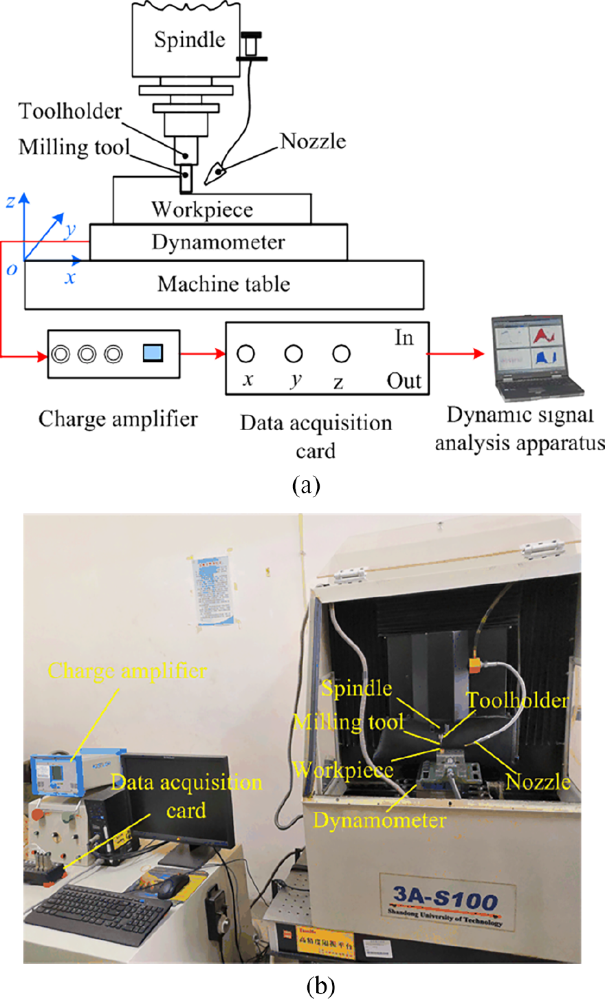
Micro-milling system: (a) schematic diagram and (b) the experimental setup.
The workpiece materials H59 brass and 6061 aluminum were used in the tests. Both materials were 10 mm × 10 mm × 20 mm in size and the top surface of the workpiece was pre-milled to remove surface defects prior to the experiments. The surface roughness of the workpiece was measured after pre-milling, as shown in Table 1. The hardness of the workpiece was measured as 146.8 HV for H59 brass and 104.7 HV for 6061 aluminum.
The surface quality of the prepared workpiece.
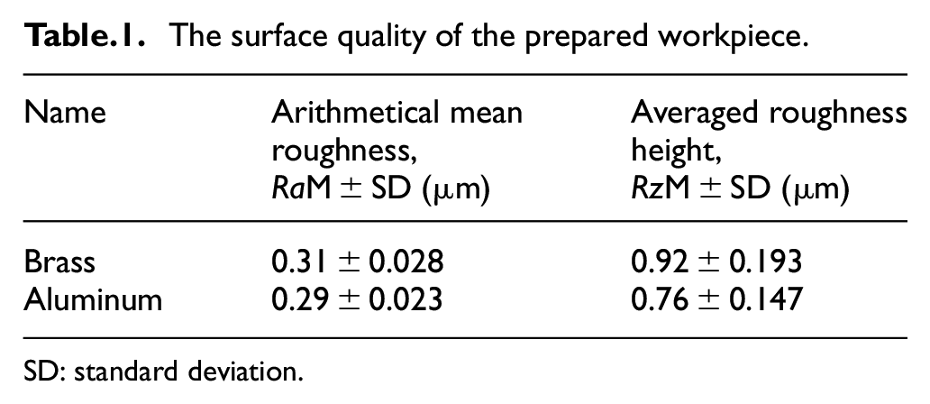
SD: standard deviation.
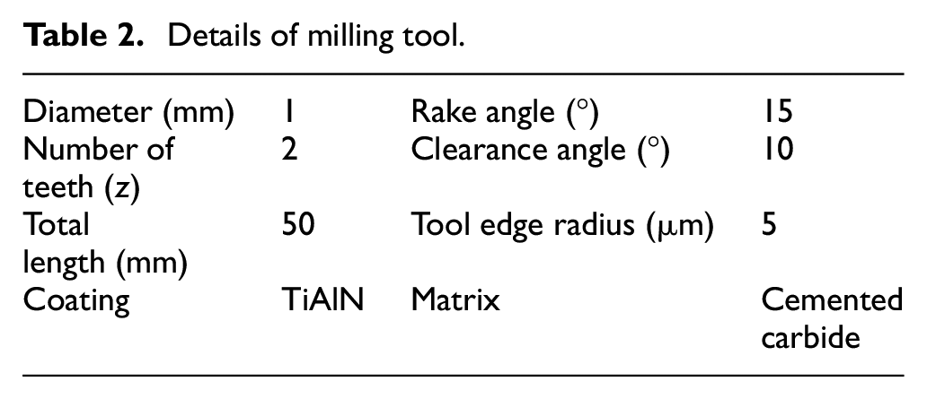
H59 brass has high strength and excellent plasticity, which can be used as a deep drawing part because of withstanding pressure well under hot conditions. 6061 Aluminum was commonly used as aerospace material as a result of its excellent processing performances and good corrosion resistance abilities. Accordingly, the selected materials were generally representative. TiAlN-coated milling tool with 1 mm diameter was used in the tests. The hardness of coating was 2800 HV and the oxidation temperature was 800 °C. Due to the high content of Al in TiAlN coating, aluminum oxide was easy to be formed in the processing process, which played a protective role on the tool surface. Hänel et al. 19 found that the surface quality of the tool has a significant effect on friction and cutting force. Therefore, the surface of the tool was observed to ensure flawlessness before experiments. The specific parameter of tool is shown in Table 2.
Details of milling tool.
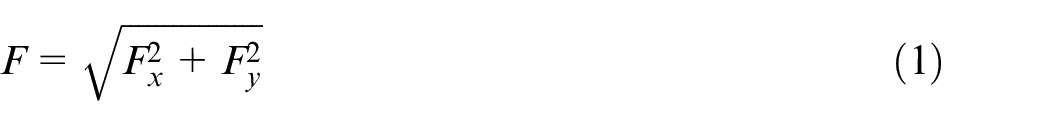
Cutting force was crucial index reflected the cutting state of tool–workpiece. As shown in Figure 1, cutting force was measured by a three-dimensional force measurement system (Kistler 9257B) under different cooling and lubrication conditions. The system consists of a three-dimensional dynamometer, a multi-channel charge amplifier, an A/D data acquisition card, and a PC. The sampling frequency of cutting force was set to 7000 Hz, and the data were analyzed by computer software. For comprehensively evaluating the influence of cooling and lubrication conditions on cutting force, resultant force F was calculated using equation (1)
After the experiments, the surface roughness of the workpiece was measured six times with a CS-3200 roughness meter. Tool wear was observed six times with quanta 250 electron microscope, and the mean values were taken as the measurement results. The surface composition of tool was analyzed by Energy Dispersive X-Ray Spectroscopy (EDX). Side edge wear (VB) was the amount of tool outer edge wear measured at the 1/2 length of the tool side edge, as shown in Figure 2. Then, the mean of these five values was further analyzed.
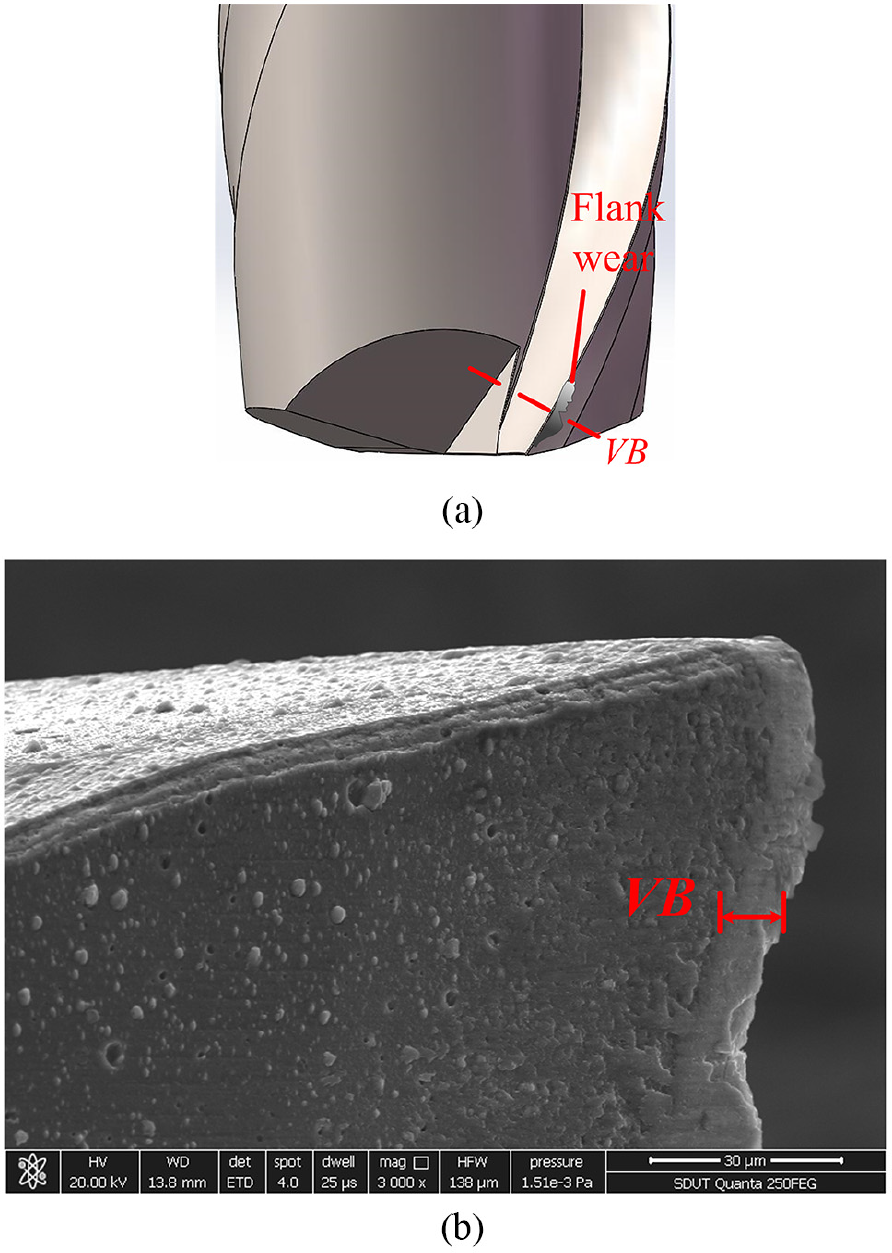
Measurement of tool wear: (a) 3D schematic and (b) tool wear diagram.
The EFFIGIENT B804 lubricant (1:20 oil-to-water ratio) was chosen for MQL and flood cooling conditions in the experiments. The cooling and lubrication equipment is shown in Figure 3. The specific conditions for micro-milling experiments are shown in Table 3. Besides dry condition, nozzle was placed at the tool entry point under other cutting conditions. The distance from the nozzle to tool was fixed at 50 mm.
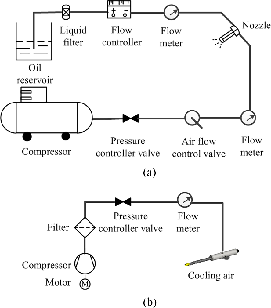
Schematic diagram: (a) MQL and (b) jet cold air.
Cutting fluids.
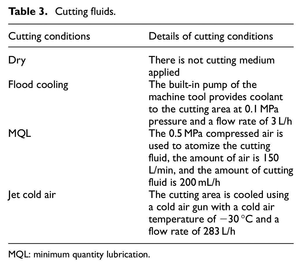
MQL: minimum quantity lubrication.
Experimental design
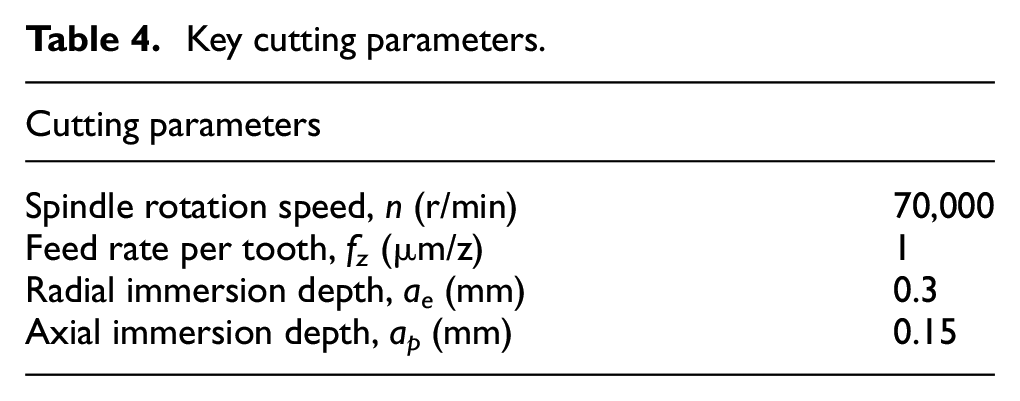
In the experiments, the effects of cutting fluids on tool wear, cutting force, surface roughness, and sustainability were studied. The cutting length was 440 m; tool wear and surface roughness were measured every 110 m. The cutting parameters are shown in Table 4. The experiments were repeated three times to ensure the accuracy and stability of the data. Tool wear were measured six times, and the average value was taken as the result of one test. The average data from three experiments were taken as the final result, and the standard deviation (SD) of average was indicated by the error bar in the figures.
Key cutting parameters.
Results and discussion
Tool wear
The tool wear is inevitable, which is directly related to machining efficiency and quality. Figure 4 shows the tool wear as a function of cutting length under various cutting conditions during milling of H59 brass. It can be seen from Figure 4(a) that tool wear shows different upward trends as cutting length increases. Tool wear increases from a large slope to a small slope under MQL and flood cooling conditions. It presents a rising trend gradually under dry and jet cold air conditions. This shows that different cutting conditions have different effects on tool wear. In addition, tool wear from the least to the largest in sequence is the MQL, flood cooling, jet cold air, and dry cutting for the same cutting length. MQL performs better than other cutting fluids in reducing tool wear. Similar result was found by Li and Chou; 20 it is found that the application of MQL significantly reduced the tool wear compared to those in dry cutting based on slotting tests by micro-milling. This can be explained by the fact that MQL has good cooling lubrication and reduces friction. The atomized cutting fluid is more likely to form a lubricant film in the tool–workpiece interface, which reduces friction in the cutting area and reduces tool wear. On the contrary, the effect of other cutting fluids on cooling and lubrication is poor. Especially, the tool wear value has always been the highest under dry cutting condition.
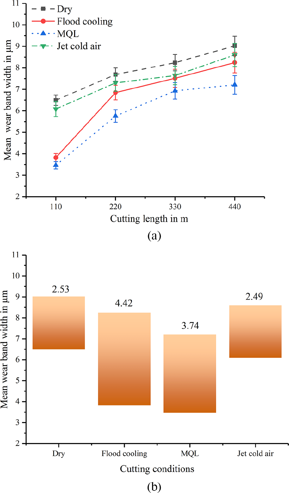
Tool wear in micro-milling of H59 brass: (a) variation of tool wear and (b) range of tool wear.
The range of tool wear can reflect the performances of cutting fluids. Figure 4(b) shows the range of tool wear values obtained for 110–440 m under different conditions. It can be clearly noticed that the minimum range of tool wear value is jet cold air, and flood cooling does not perform well in this aspect. This indicates that jet cold air condition has greater stability in terms of tool wear during micro-milling of brass. In addition to this, dry compared to jet cold air conditions, it can be seen that the lowest values are similar. The highest value is 0.4 μm larger for dry than that for jet cold air. This designates that jet cold air is more suitable than dry condition.
However, tool wear in micro-milling of 6061 aluminum is shown in Figure 5. For Figure 5(a), cutting length is less than 220 m, tool wear increases slowly under dry and jet cold air conditions, and then it increases sharply over 220 m. The values of tool wear increase gradually under the other two conditions. Since the heat generated by the friction between tool and workpiece is a process of accumulation, the temperature is low at initial cutting stage, and tool wear rises slowly. Furthermore, there is no cooling medium in dry; the temperature sharply rises over a certain cutting length. 21 Moreover, it has been observed from Figure 5(a), the tool wear value reaches the maximum for dry cutting, followed by jet cold and flood cooling, and the minimum for MQL. The range of tool wear during micro-milling of aluminum is shown in Figure 5(b). It shows that the minimal range of tool wear values is achieved by MQL. The performance is very poor in dry cutting condition.
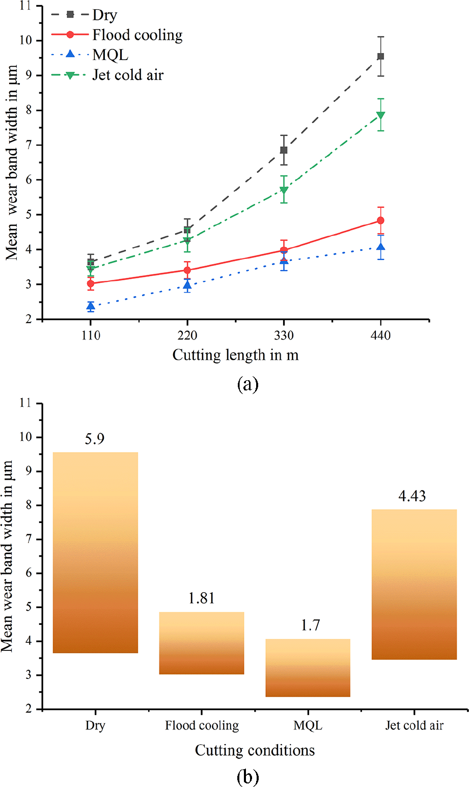
Tool wear in micro-milling of 6061 aluminum: (a) variation of tool wear and (b) range of tool wear.
From Figures 4 and 5, tool wear values are more severe in the brass experiment than that in the aluminum experiment. The ranges of the tool wear values are quite different. It can be explained by the hardness and properties of the two materials. Furthermore, the tool wear is lower under MQL and flood cooling conditions than that of other two conditions, which indicates that cutting fluid can reduce the friction between the tool and workpiece, and plays a better cooling and lubrication role.
For further investigation, the tool wear patter was observed by scanning electron microscopy (SEM). When the cutting length is 440 m, tool wear patterns under different cutting conditions are shown in Table 5. It reveals that the tool tip is blunt and rounded under different cutting conditions in two material experiments, which indicates that the tool tip is more prone to wear due to the stress concentration on the tip during micro-milling. Meanwhile, compared with other conditions, abnormal wear on tool occurs in dry and jet cold air, which leads to reduced cutting capacity and increased processing costs. Then, the tool is cleaned by ultrasonic wave cleaner, and there are still a lot of materials adhering to the tool surface. When the workpiece moves relative to the tool, materials take away the coating, which further aggravates tool wears. On the contrary, due to the protection of cutting fluid, there is no abnormal wear under MQL conditions. It indicates that MQL condition can reduce tool wears and is more suitable for machining.
Tool wear patterns at 440 m cutting length.
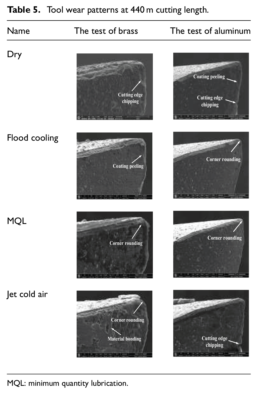
MQL: minimum quantity lubrication.
The tool wear mechanism is further discussed as shown in Figure 6. It illustrates the bonding material on the rake face, as shown in Figure 6(a). Energy spectrum analysis is carried out at points A and B to determine the composition of material. Compared with the results at point B (Figure 6(d)), Mg and other elements exist at point A (Figure 6(c)), which proves that the material is 6061 aluminum. The chip is attached to tool surface to form BUE under high temperature and pressure; tool coating is carried away by the BUE, which results in adhesive wear when workpiece and tool move relatively to each other. 22 As shown in Figure 6(b), the carbide hard points exist and the chip causes the scratches on the flank tool to form abrasive wear. It is a mechanical frictional wear that eventually causes the coating peeling and exacerbating tool wear.
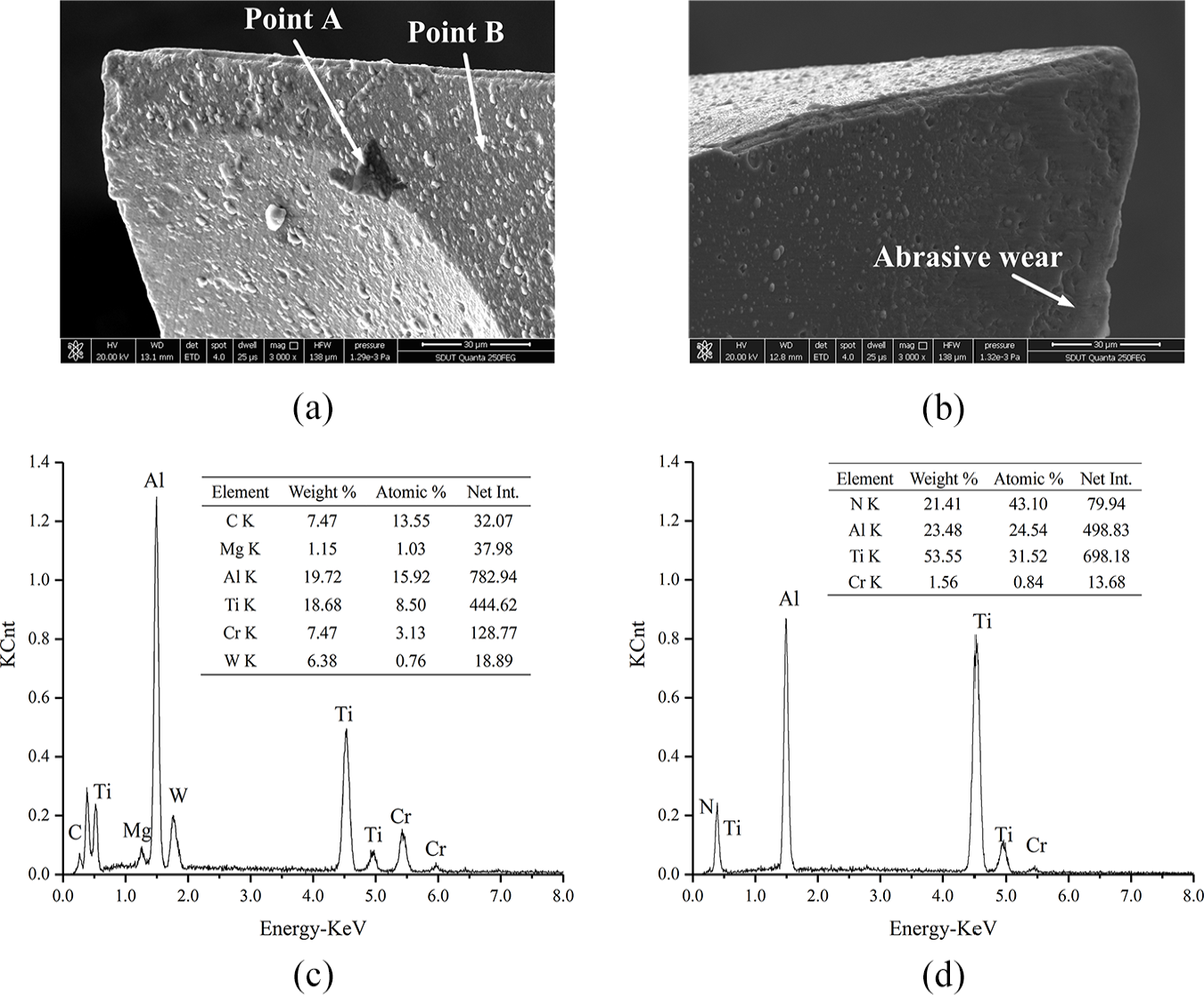
Tool wear mechanism: (a) bonding material, (b) abrasive wear, (c) EDX analysis of point A, and (d) EDX analysis of point B.
Surface roughness
The surface roughness is one of the important factors affecting machining quality. Arithmetic mean roughness Ra and averaged roughness height Rz are further analyzed in this article.
Figure 7 shows the surface roughness of brass under various cutting conditions. In Figure 7(a), it is observed that arithmetic mean roughness Ra gradually increases with respect to the increased cutting length under all conditions. Moreover, the arithmetic mean roughness Ra reaches the largest value under dry cutting conditions, followed by jet cold air and flood cooling. Ra reaches the smallest value under MQL. For dry condition, the chip is not easy to be discharged and the tool wear patterns (Table 5) are serious, which makes the machined surface more seriously damaged. On the contrary, oil mist penetrates the cutting zone, taking away frictional heat to lower the temperature. Therefore, the adhesion between the tool and chip is reduced. From Figure 7(b), averaged roughness height Rz and arithmetic mean roughness Ra have similar trends.
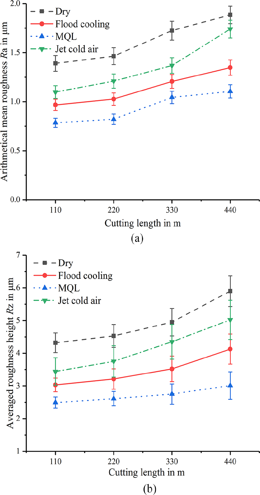
The surface roughness of H59 brass: (a) arithmetical mean roughness Ra and (b) averaged roughness height Rz.
The surface roughness of aluminum is shown in Figure 8. It shows that the longer the cutting distance is, the larger the arithmetic mean roughness Ra and averaged roughness height Rz will be. Meanwhile, the surface roughness reaches the maximum value under dry cutting and the minimum under MQL condition. It is the same as the brass test results.
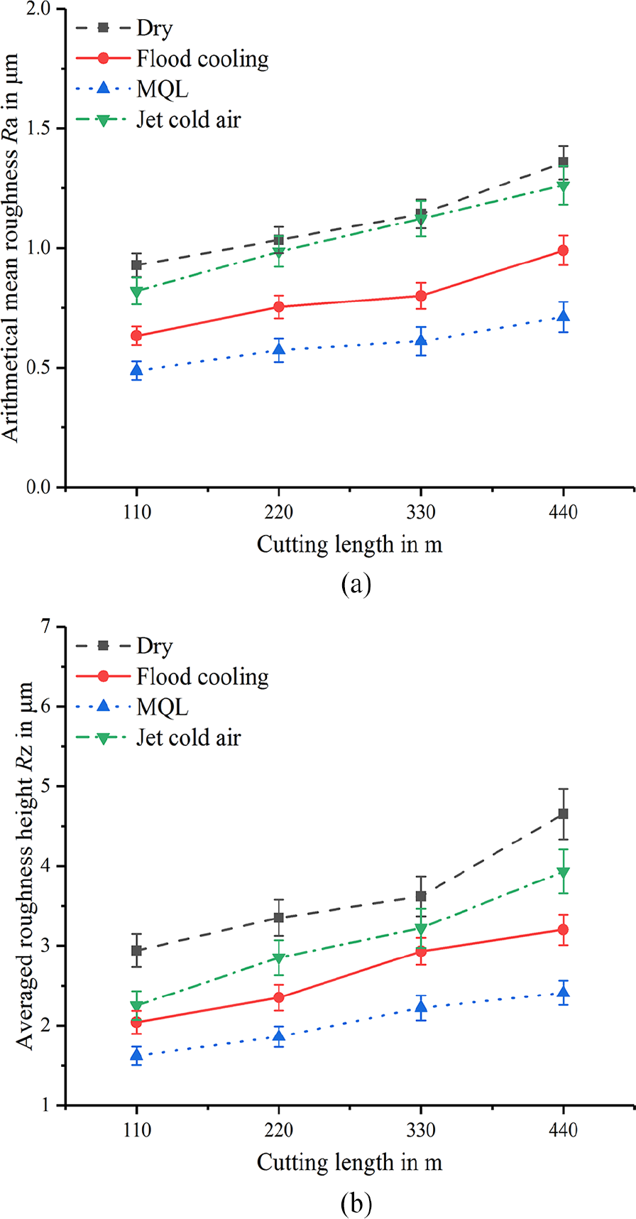
The surface roughness of 6061 aluminum: (a) arithmetical mean roughness Ra and (b) averaged roughness height Rz.
However, the diagram of Figures 7 and 8 shows clearly that the surface roughness of 6061 aluminum is better than that of H59 brass under the same cutting condition. MQL performs best, followed by flood cooling and jet cold air, dry performs worst in terms of surface roughness. Compared with Figures 4(a) and 5(a), the order of surface roughness value is the same as that of tool wear under different cutting conditions. It shows that there is a close relationship between surface roughness and tool wear. The trend of surface roughness can reflect the tool wear, which can help to distinguish the tool wear. The results are in accordance with that from the literature. 23 In conclusion, MQL can effectively reduce the surface roughness of machined surface and improve the surface quality of the finished workpiece.
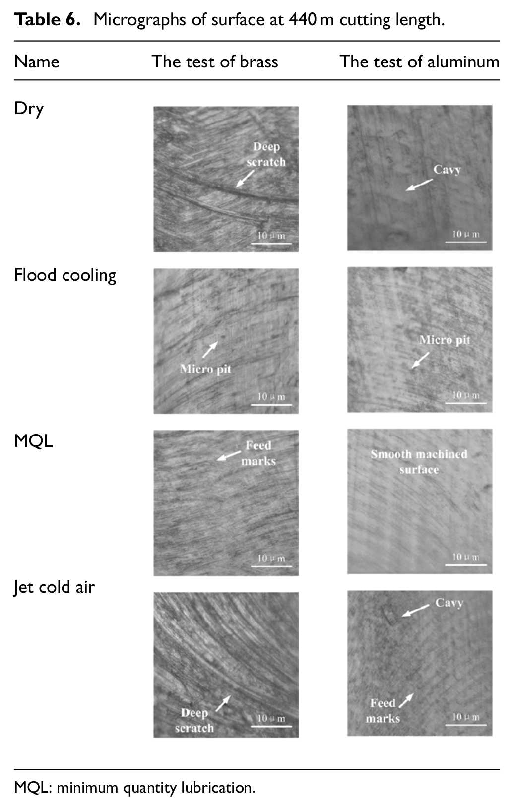
Surface morphology is a key factor affecting the function and reliability of parts, and it is worthy of further discussion. Micrographs of machined surface are shown in Table 6 when cutting length is 440 m. For dry cutting condition, it is clearly observed that the material cavy and deep scratch are the common surface defects. This phenomenon is caused by a broken cutting edge caused by excessive tool wear, like tool wear patterns in Table 5. Surprisingly, the deep scratch and feed marks are observed under jet cold air. The most likely cause is premature breakage of the tool cutting edge. The reason may be that no lubricant film is formed. The micro-pit occurs on the surface for flood cooling. In addition, the surface is found to be almost defect free under MQL. This also proves that MQL can help to achieve higher surface quality. Recently, compared with the dry and flood cooling conditions, the indentation and scratch generated are less in MQL processing; the surface quality is better as found by Masoudi et al. 24
Micrographs of surface at 440 m cutting length.
MQL: minimum quantity lubrication.
Cutting force
As shown in Figure 9, the cutting forces for all experiments are measured by dynamometer. The same conclusions could be made by the cutting force collected during machining, the longer the cutting length, the greater the cutting force in Figure 9(a) and (b). It is observed that the cutting force of H59 brass is larger than that of 6061 aluminum material.
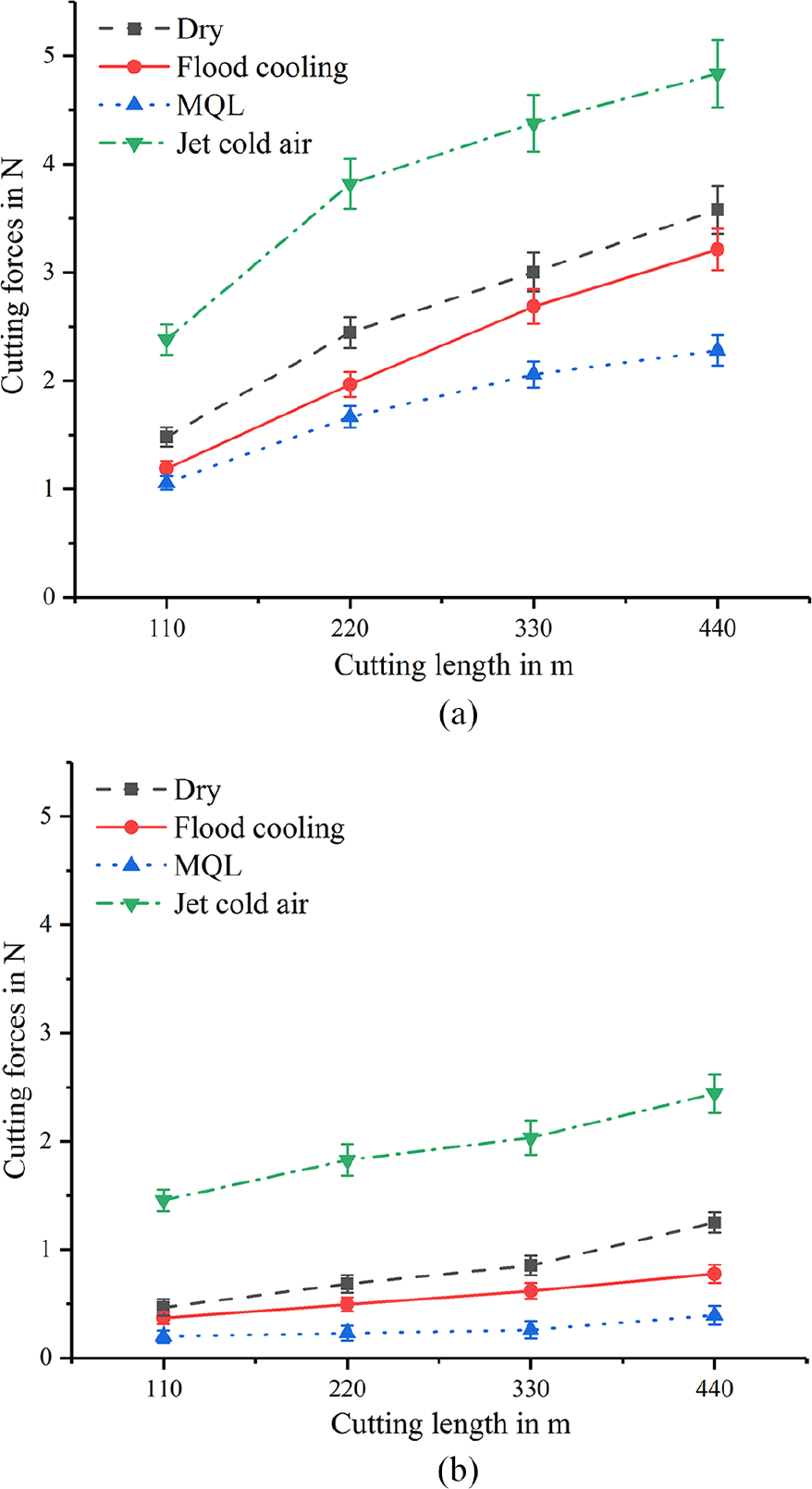
Variation of cutting force: (a) cutting force in milling H59 brass and (b) cutting force in milling 6061 aluminum.
However, compared to tool wear (Figures 4 and 5) and surface roughness (Figures 7 and 8), the cutting conditions have different orders of influences on cutting force. With the same cutting length, the cutting force is the largest under jet cold air, followed by the condition of dry and flood cooling, the smallest is MQL condition. The reasons for this change are further explored as follows. Body-centered cubic lattice materials are prone to low-temperature embrittlement, and its cutting force is reduced during cutting. Nevertheless, H59 brass and 6061 aluminum do not have low-temperature brittleness, and their strength and hardness will increase with decreasing temperature. 25 Therefore, with the increase in the tool wear and the lower temperature for workpiece, the cutting force under jet cold air condition is much higher than that of other conditions. Furthermore, the large friction between the tool and the workpiece causes the cutting force to increase in dry cutting. The increase in the cutting force is not obvious due to lubrication and cooling under the other two cutting conditions. Cutting force can reflect the friction state between the tool and the workpiece. The cutting force is minimal under MQL condition in all experiments. Hence, MQL can more effectively delay the increase in the cutting force in machining, improving friction between tool and workpiece.
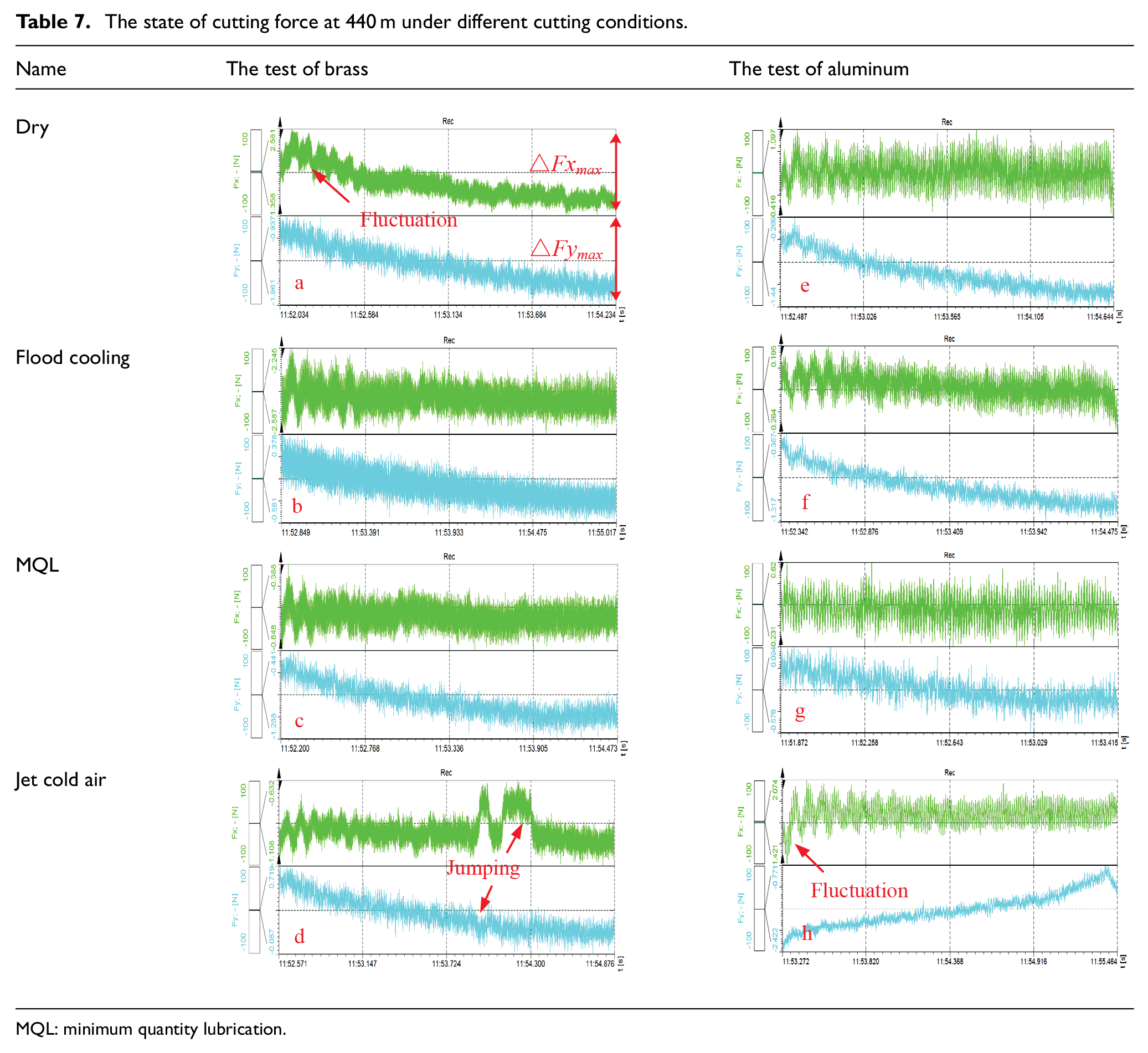
When the cutting length is 440 m, the cutting forces Fx and Fy under different cutting conditions are shown in Table 7. For the states of cutting force, the jumping is observed for cutting forces under chilled air and dry cutting conditions. As shown in Table 5, the tool is damaged in dry and jet cold air cutting conditions. The cutting edge chipping occurs on tool, which leads to the decline of cutting ability of tool and the instability of cutting force. According to the data in Table 7, the maximum difference between Fx and Fy is calculated separately, as shown in Figure 10. The symbols a to d in the horizontal axis represent the cutting force states under dry, flood cooling, MQL, and jet cold air conditions in the brass tests, respectively. The symbols e to h represent the cutting force states under the four cutting conditions of the aluminum alloy tests, respectively. At the same time, the symbols a to h have been inserted in Table 7 for a clearer understanding. It is observed that the minimum value of ΔFx appears in the flood cooling, and the ΔFy appears in MQL in the micro-milling of brass. In addition, the smallest ΔFx and ΔFy values appear in MQL in the micro-milling test of aluminum. Meanwhile, the maximum values of ΔFx and ΔFy appear on dry cutting condition in both material tests. Based on the above analysis, the cutting force is more stable under MQL condition and does not fluctuate largely.
The state of cutting force at 440 m under different cutting conditions.
MQL: minimum quantity lubrication.
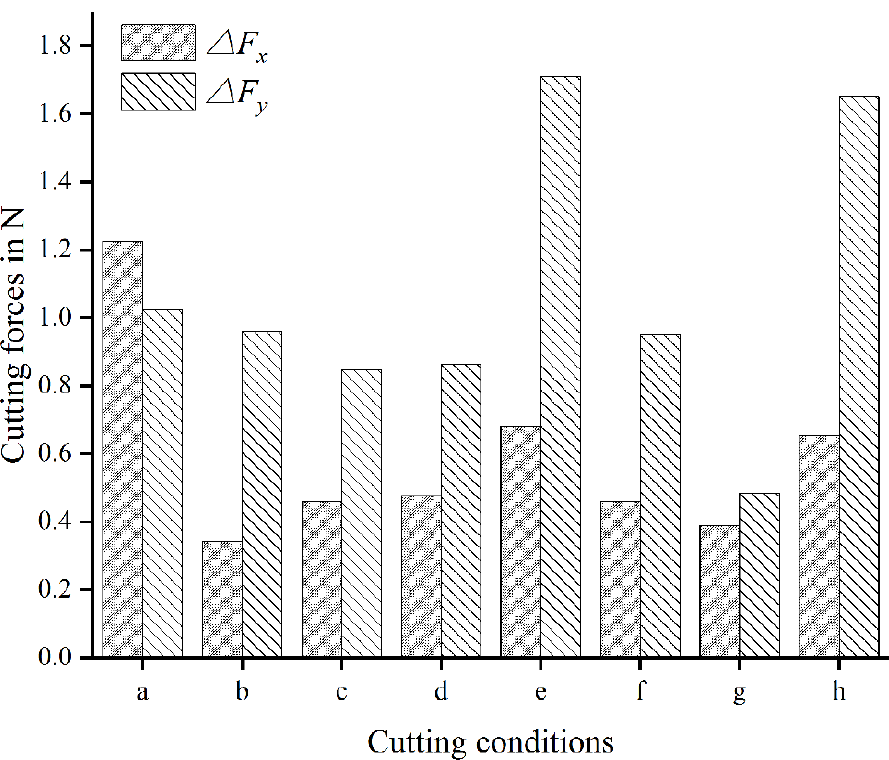
The value of ΔFx and ΔFy.
The differences in cutting forces are minimal. An error analysis would therefore be necessary. The standard error (SE) is sensitive to the larger error or smaller error in a set of measurements, which is a better way to express the accuracy. The relative error (RE) can better reflect the reliability of the measurement, as shown in Tables 8 and 9. The SD is shown in the figure as an error bar. The same test was repeated three times, test 1, test 2, and test 3 represented the average cutting force in each test, respectively, in this table. Average values were obtained from six times measurements. From Tables 8 and 9, the RE is within 10%, and the SE is within a reasonable range, which indicates that the cutting force is accurate.
Analysis of cutting force error in H59 brass.
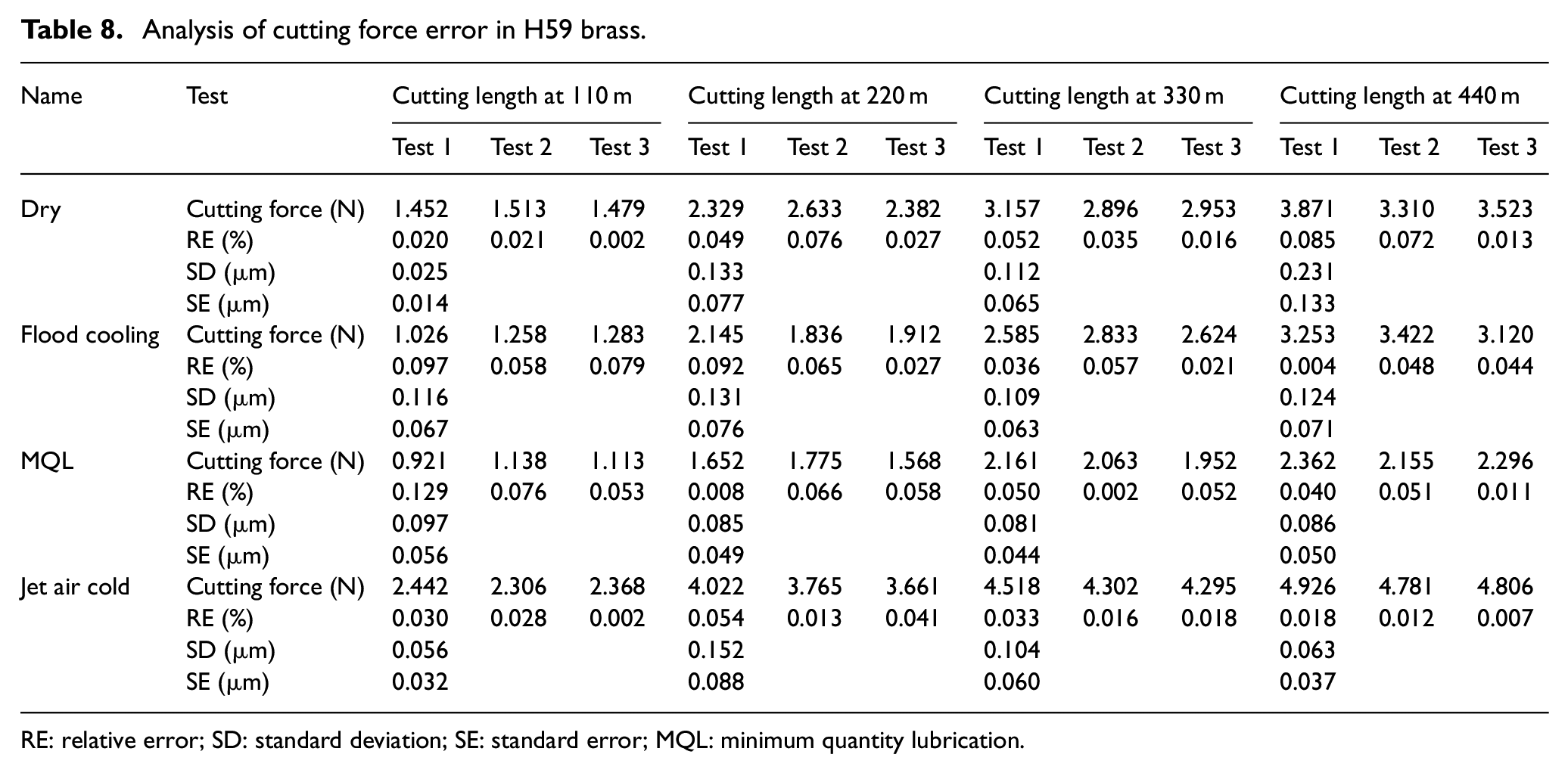
RE: relative error; SD: standard deviation; SE: standard error; MQL: minimum quantity lubrication.
Analysis of cutting force error in 6061 aluminum.
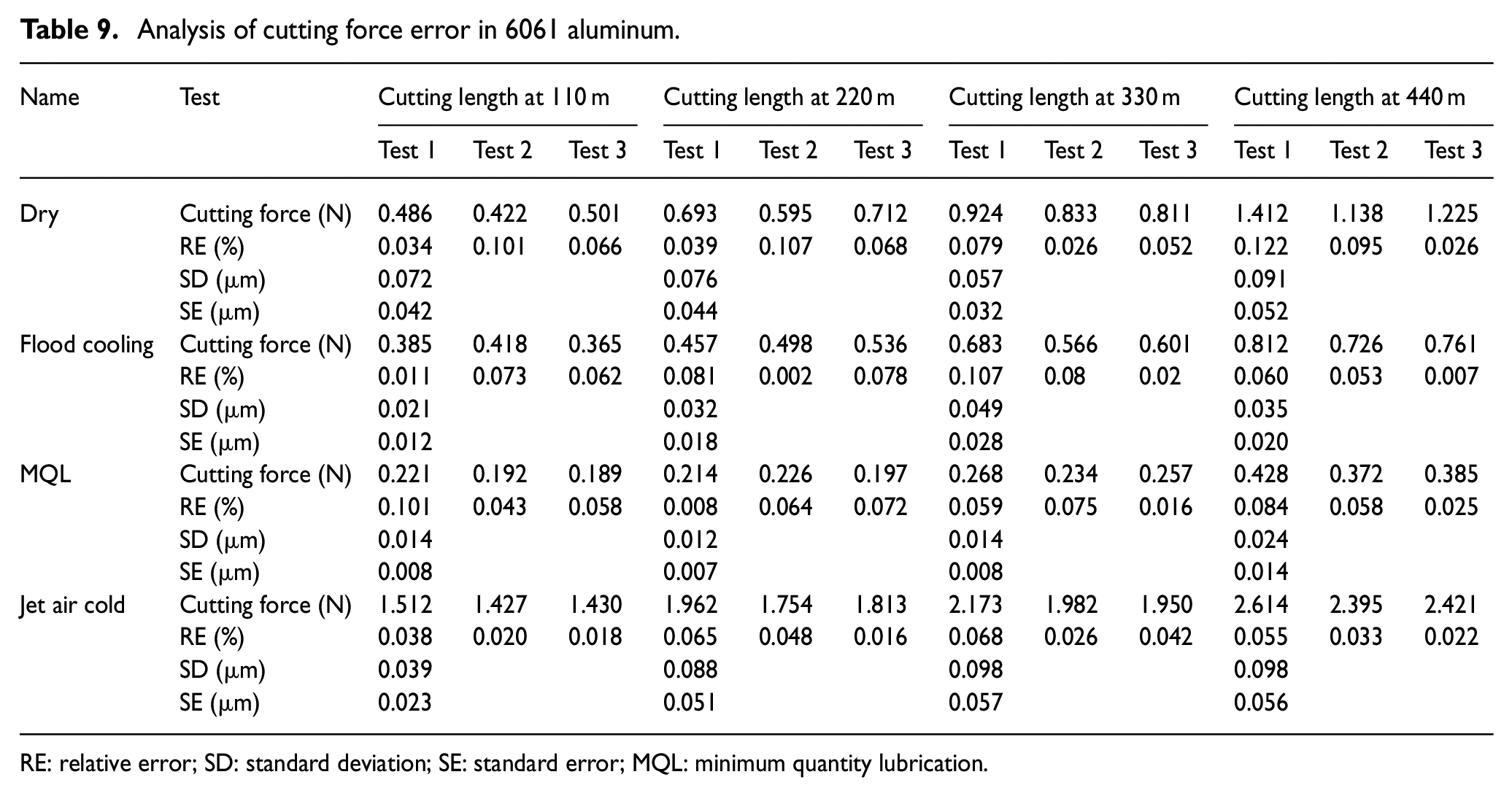
RE: relative error; SD: standard deviation; SE: standard error; MQL: minimum quantity lubrication.
Analysis of results on sustainability and machining tests
Sustainability assessment of cutting conditions
Cleanliness and sustainable production were paid more attention in modern industrial manufacturing. The industry-related research results are required to comply with these rules. Sustainable mechanical manufacturing was not only associated with productivity and product quality but also associated with environmental pollution and worker health. There are some references in the introduction section to the sustainability advantages of different cutting conditions. In this article, the Pugh matrix environmental approach was used to quantify the sustainability of different cutting conditions during micro-milling, as shown in Table 10. Pugh matrix was a matrix representing the relationship between decision scheme and related factors. 26 It mainly focused on the comparison of multiple factors, and the factor was given a weightage in order to get better results. Take one of several factors as the level standard, and the other options were compared in pairs to obtain the results. 27 The method consists of four main procedures:
Procedure 1: Identify all factors. The factors to be compared are determined, and weightage is used to indicate the factors that need to be focused on according to the importance of the factors.
Procedure 2: Selection of standard. Select one of the known performance and results as the evaluation criteria, and label it with S.
Procedure 3: Comparison procedure. The results and performance selected in procedure 2 are used as the basis, and other factors are compared one by one with the standard. If the result is better than the standard, it is expressed as +1. If the performance is poor, it is expressed as −1. Similarly, in the case of much superior and much worse results, +2 and −2 have been given. The better it performs, the higher the score.
Procedure 4: Analysis of results. Sum the score, the factor that gets the highest score is the appropriate choice.
Pugh matrix comparison for the cooling techniques.
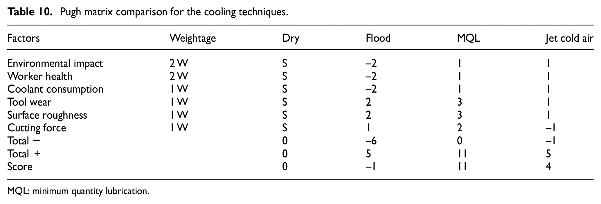
MQL: minimum quantity lubrication.
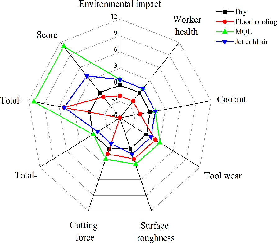
In this study, the sustainability of cutting conditions was assessed in terms of environmental impact, worker health, coolant consumption, tool wear, surface roughness, and cutting force. On the premise of sustainability, the most important factors were environmental impact and worker health, which were assigned two weightages, and other factors were assigned one weightage. The dry cutting had been taken as the datum or baseline condition. As can be seen from Table 10, dry cutting was used as a benchmark, and its factors were marked as S, with a total score of 0. Cutting fluid was not used under jet cold air, and trace amount of cutting fluid was used under MQL condition. As this process did not cause any form of emission, these two cutting conditions had little harm to environmental impact and worker health, which had resulted in further saved in the purchase of coolant. On the contrary, that a large amount of cutting fluid was used resulted in increased production costs during processing under flood cooling condition. It was difficult for cutting fluid to be recycled, which results in environmental pollution. Harmful substances in the cutting fluid can also be harmful to human health. Therefore, MQL and jet cold air were assigned to +1, and flood cooling was assigned to −2. Moreover, dry cutting was taken as standard; other cutting conditions were assigned a score based on the test results in terms of tool wear, surface roughness, and cutting force from Figures 4, 5, and 7–9. Based on data in Table 10, a radar diagram was drawn, as shown in Figure 11.
Compared the environmental, economical, and technical aspects of different cooling systems.
In conclusion, dry cutting is a good choice without considering the effect of high temperature on processing, especially in the medical field. Flood cooling is not desirable regardless of any aspects. Jet cold air is a good option in micro-milling, but the best is MQL condition. In addition, more explorations are needed in practical industrial applications.
Machining tests
As mentioned above, MQL performs well in terms of sustainability and processing performance. The results can be applied to practical productions, under the premise of satisfying the sustainability. In the field of micro-parts, micro-thin walls have been paid special attention, where the vertical thin wall was mostly studied. But it is difficult to process the curved thin wall as burr, size, and other problems.28,29 Therefore, a quarter of the miniature sleeve with a radius of 2 mm was processed to test the practicality of the research results. This feature was a curved thin wall with a width of 60 μm and a height of 600 μm. The workpiece was made of brass material by micro-milling under dry and MQL conditions. Other settings were the same as described above.
As shown in Figure 12, curved thin walls were manufactured under different cutting conditions. Figure 12(b) shows that more chips are attached to the thin wall, and uneven burrs appear on both sides. Significant feed marks are found where the thin wall curved to the left, which may be caused by a lack of lubrication in the tool–piece contact area. The dimension of the thin wall was measured with a dimensional error of 17.2%. On the contrary, the above problems hardly appeared in Figure 12(c). The dimensional error of the thin wall was only 2.25%. It shows that MQL has great potential for industrial applications during micro-milling.
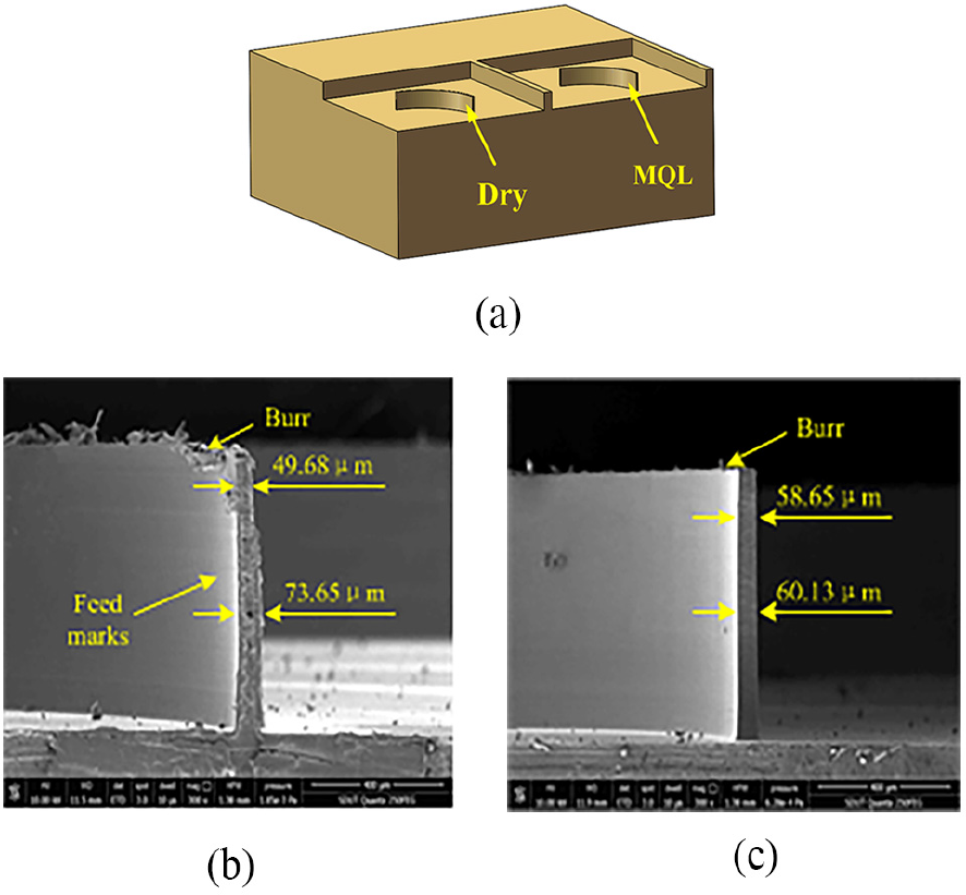
The picture of curved thin wall: (a) overall picture of the workpiece, (b) by dry cutting, and (c) by MQL.
Conclusion
The effects of cutting fluids (dry, flood cooling, MQL, and jet cold air) on tool wear, surface roughness, and cutting force were studied for two different materials. In addition to this, the sustainability of cutting conditions was evaluated by the Pugh matrix approach. Practical cutting tests have been successfully conducted. The major conclusions are summarized as follows:
The experimental results showed that the MQL cutting condition had a significant positive effect on tool wear, surface roughness, and cutting force. By increasing the cutting length, the tool wear, surface roughness, and cutting force all increased for two different materials tests. However, MQL consistently performed best in these three aspects. The values of tool wear, surface roughness, and cutting force were lower under MQL condition. For tool wear patterns and surface morphology, tool breakages and surface defects were significantly reduced compared to other cutting conditions. There was no significant fluctuation in the cutting force. Micro-milling process is more stable cutting state under MQL condition.
The tool tip was more vulnerable to damage in micro-milling process. Coating peeling and corner rounding were the main tool wear patterns. The tool wear mechanisms were abrasive wear and adhesive wear. Furthermore, excessive tool wear causes surface quality to decline and cutting force to jump. This showed that surface quality and cutting force could reflect tool wear.
The sustainability of cutting conditions was assessed and the results showed that MQL conditions not only improved the economic and technical aspects of the process but also improved issues related to the environment and operator health.
A curved thin wall was processed under dry cutting and MQL conditions. The dimensional error of the thin wall is only 2.25%, and there are almost no burrs and scratches under MQL. The method and results introduced in this article have potential industrial applications.
Future scope
Future research is focused on the evaluation process ability and sustainability of difficult-to-machine and medical materials. The influence of micro-particles on MQL technology will be explored further. In addition, double or more nozzle heads are to be tested to solve the phenomenon of uneven cooling. Combining the above points, more cutting conditions associated with practical industrial applications will be explored.
Footnotes
Declaration of conflicting interests
The author(s) declared no potential conflicts of interest with respect to the research, authorship, and/or publication of this article.
Funding
The author(s) disclosed receipt of the following financial support for the research, authorship, and/or publication of this article: This article was financially supported by the National Key Research and Development Program of China (2018YFB2001400) and the SDUT & Zibo City Integration Development Project (2017ZBXC189).