
Abstract
This article presents a new pulse discriminating system for process monitoring of wire electrical discharge turning. The pulse discriminating device, including a spark gap monitor and a digital signal processor card, has been developed to identify four major gap states classified as open circuit, normal spark, arc discharge and short circuit based on the characteristics of gap voltage waveform as well as compute ignition delay time for each open circuit and normal spark. By means of this system, the proportion of open circuit, normal spark, arc discharge and short circuit to total sparks and average ignition delay time within a time interval of 200 ms can be analyzed quantitatively during the wire electrical discharge turning process. It has been observed that thread cutting using wire electrical discharge turning exhibited more stable machining than cylindrical wire electrical discharge turning under a servo feed machining condition because servo feed control of the cylindrical wire electrical discharge turning process only focused on keeping forward sparking gap at a proper width, but it failed to respond to the variation of lateral gap width due to an independent motion of the rotary axis with respect to the translational axis. Experimental results also demonstrate that these pulse train data and average ignition delay time can substitute for average gap voltage as sensing parameters for on-line monitoring and control of the wire electrical discharge turning process.
Keywords
Introduction
Wire electrical discharge machining (wire-EDM) has been a widely accepted non-traditional material removal process in tool and mold industries because of its excellence in precisely producing intricate two-dimensional shapes and varying tapers in all electrically conductive materials irrespective of their hardness and toughness. Recently, with rapid developments in automotive, aerospace, biomedicine, microelectromechanical system (MEMS) and cutting tool industries, there is a growing demand for three-dimensional machining capabilities in wire-EDM. By mounting a rotary part device on the machine table of a conventional five-axis wire-EDM machine, wire electrical discharge turning (WEDT) process was developed to generate precise cylindrical and threaded forms on hard, difficult-to-machine materials. Several studies have been made to investigate the machining characteristics of the WEDT process. Qu et al. 1 proposed a mathematical model for achieving high material removal rate machining of free-form cylindrical geometries in WEDT. They also investigated the surface integrity and roundness of cylindrical parts fabricated by the WEDT process. 2 Mohammadi et al. 3 investigated the effect of process parameters on surface roughness and roundness in cylindrical wire electrical discharge turning (CWEDT) using Taguchi approach. Haddad et al. 4 proposed two predictive models of the CWEDT process for the evaluation of surface roughness and roundness of the machined parts under various machining conditions. Gjeldum et al. 5 investigated the influence of maximum pulse current, pulse pause duration and rotation speed on material removal rate by means of design of experiments (DOE). They also presented some polynomial models and a neural network model for the prediction of material removal rate in CWEDT. Weingartner et al. 6 investigated the influence of high-speed rotating workpiece in WEDT and developed an electro-thermal model to examine the effect of relative speed on eroded craters. Krishnan and Samuel 7 presented a back-propagation feed-forward artificial neural network for modeling of the WEDT process and proposed a multi-objective optimization method based on non-dominated sorting genetic algorithm II for the optimization of material removal rate and surface roughness. Mohammadi et al. 8 investigated the influence of ultrasonic-assisted WEDT on discharge column behavior acting on workpiece surface. They reported that using the ultrasonic vibration in WEDT was an efficient method to improve surface integrity and increase material removal rate. Gjeldum et al. 9 investigated the influence of process parameters and workpiece dimensions on material removal rate in CWEDT. They also presented some examples of poor machining accuracy, which were produced with inappropriate pulse parameter setting for the CWEDT process.
Machining performance of the WEDT process depends greatly on machining settings as well as discharge conditions between the workpiece and the wire electrode. Average gap voltage is commonly used to evaluate discharge conditions for the wire-EDM process, but it often fails to provide subtle information on the spark gap for process monitoring and control. Many researchers and manufacturers have been devoting themselves to develop pulse discrimination systems or spark gap monitors based on the characteristics of gap voltage and current waveforms for process monitoring of EDM or wire-EDM. Dauw et al. 10 reported an EDM gap parameter monitoring system that could classify discharge pulses into 15 pulse types by combining some of the time and voltage characteristics. Watanabe et al. 11 classified discharge pulses into three categories: normal, deion and arc according to discharge pulse profile by means of a new wire-EDM monitoring system. Liao and Woo 12 presented a pulse discrimination system to investigate the effect of machining parameters on the characteristics of pulse trains during the wire-EDM process. Kwon and Yang 13 developed a real-time instantaneous energy monitoring system to monitor the transient state of the wire-EDM process for improving efficiency and performance. Yan and Chien 14 developed a pulse discriminating and control system based on the characteristics of gap voltage waveform for micro-wire-EDM process. Cabanes et al. 15 presented an acquisition system based on the characteristics of current and voltage signals to obtain an extensive experimental database for on-line detection of instability and wire breakage in wire-EDM. Liao et al. 16 proposed an on-line analysis system to investigate the causality of ignition delay time data sequences for evaluating the machining performance of wire-EDM. Janardhan and Samuel 17 developed a data acquisition system for off-line pulse train data analysis of the WEDT process. Blatnik et al. 18 developed a measuring system based on gap voltage and discharge current to calculate the percentage of harmful arc discharges for surface current density monitoring in EDM process.
Previous studies1–9 regarding the WEDT process focused mainly on the effect of process parameters on machining performance and finding optimal machining parameters rather than on on-line process monitoring and control, although several researchers11–17 have presented some types of pulse discriminating systems for process monitoring and control of wire-EDM. Their studies have also shown that these systems could be applied to a wide range of machining conditions. However, these systems may not provide real-time knowledge of the behavior of the discharges in the spark gap for the WEDT process in which spark gap conditions change continually with workpiece rotation, particularly for a flushing-type wire-EDM machine. In addition, some of these systems12,13,15,16 employed an expensive current probe measurement device to detect discharge current for process monitoring of wire-EDM. The high-priced current probe system might make these monitoring systems cost-ineffective in industrial application.
As demands on productivity, machining accuracy and surface quality increase continuously in the field of manufacturing, process monitoring and control are becoming more and more important for precision machine tools. It is crucial to develop an on-line monitoring system to provide more detailed information about the discharge conditions of the WEDT process. Discharge conditions vary with the rotation of workpiece during the WEDT process because of the change in discharge area between the workpiece and the electrode. Therefore, not only spark gap states such as open circuit, normal spark, arc discharge and short circuit should be distinguished and recognized but also instantaneous spark gap conditions such as sparking frequency and ignition delay time should be demonstrated and monitored during the WEDT process. This article aims to develop a novel pulse discriminating system not merely for on-line monitoring of the WEDT process but also for practical application in the field of EDM industry. Without the aid of an expensive current probe measurement device, the pulse discrimination system can identify basic four gap states and compute sparking frequency and average ignition delay time based on the characteristics of gap voltage waveform within a time interval of 100 ms. By means of the system, a clear description about the variation in pulse train data during the WEDT process can be experimentally analyzed. Experimental verification of the developed system for monitoring of the WEDT process is shown.
On-line pulse discriminating and monitoring system
Figure 1 shows gap voltage and current waveforms that were collected by a high-speed digital oscilloscope (AGILENT DSO5014A) and a current probe system (TEKTRONIX AM 503S) during the wire-EDM process. As shown in Figure 1, gap states are classified as open circuit, normal spark, arc discharge and short circuit by detecting the level of gap voltage and the duration of ignition delay time. Figure 1(a) shows two open circuits determined when gap voltage is higher than 80 V for a period of more than 45 μs, and no discharge current occurs in the spark gap. Figure 1(b) demonstrates a normal spark decided when gap voltage is higher than 80 V for a short period of less than 5 μs together with a discharge current of more than 50 A. Obviously, ignition delay time of an open circuit is larger than that of a normal spark. An arc discharge is determined by an instantaneous gap voltage of lower than 60 V together with a discharge current of more than 50 A, as depicted in Figure 1(c). Figure 1(d) shows four consecutive short circuits determined by a very low discharge voltage level of 10 V together with a discharge current of more than 50 A. It can also be visibly found from Figure 1(c) and (d) that gap voltage of an arc discharge is higher than that of short circuit. Figure 2 shows a novel pulse discriminating and monitoring system for wire-EDM process. As shown in Figure 2, a rectifier circuit was used to transfer bipolar gap voltages generated by wire-EDM into direct current (DC) voltages. The high gap voltage was then attenuated into a low voltage level for digital circuits using a voltage divider. In this study, a high-voltage differential probe with a bandwidth of 25 MHz was used as a voltage divider for measuring high-frequency gap voltage signal. Three comparators were used to generate three different states by comparing the gap voltage signal with three voltage levels 70, 40 and 7 V labeled as Vh, Vm and Vl, respectively. Photo-couplers were employed to provide the function of electronic isolation. A complex programmable logic device (CPLD) (ALTERA EPM 1270), clocked by a 24-MHz crystal oscillator, was designed to generate discriminating signals and ignition delay time signal. Figure 3 shows the timing chart of the pulse discriminating signals. As shown in this figure, Vg is the gap voltage and Ig stands for the gap current; the gap current is excluded in the input signal of the discriminating system since a current probe system is not cost-effective in practical application. QL, QM and QH are the output states of the three comparators, respectively. They remain at a high level when the gap voltage is higher than VL, VM and VH, respectively. CH is a discriminating signal generated when QL, QM and QH remain high. CM is a discriminating signal generated when QH remains low and QL and QM remain high. CL is a discriminating signal generated when QH and QM remain low and QL remains high.
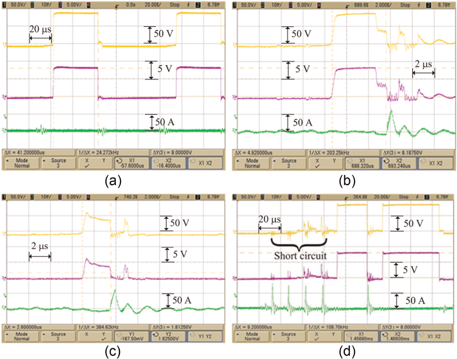
Voltage and current waveforms of four basic wire-EDM gap states: (a) open circuit, (b) normal spark, (c) arc discharge and (d) short circuit (channel 1: gap voltage; channel 2: discharge current; channel 3: attenuated gap voltage).
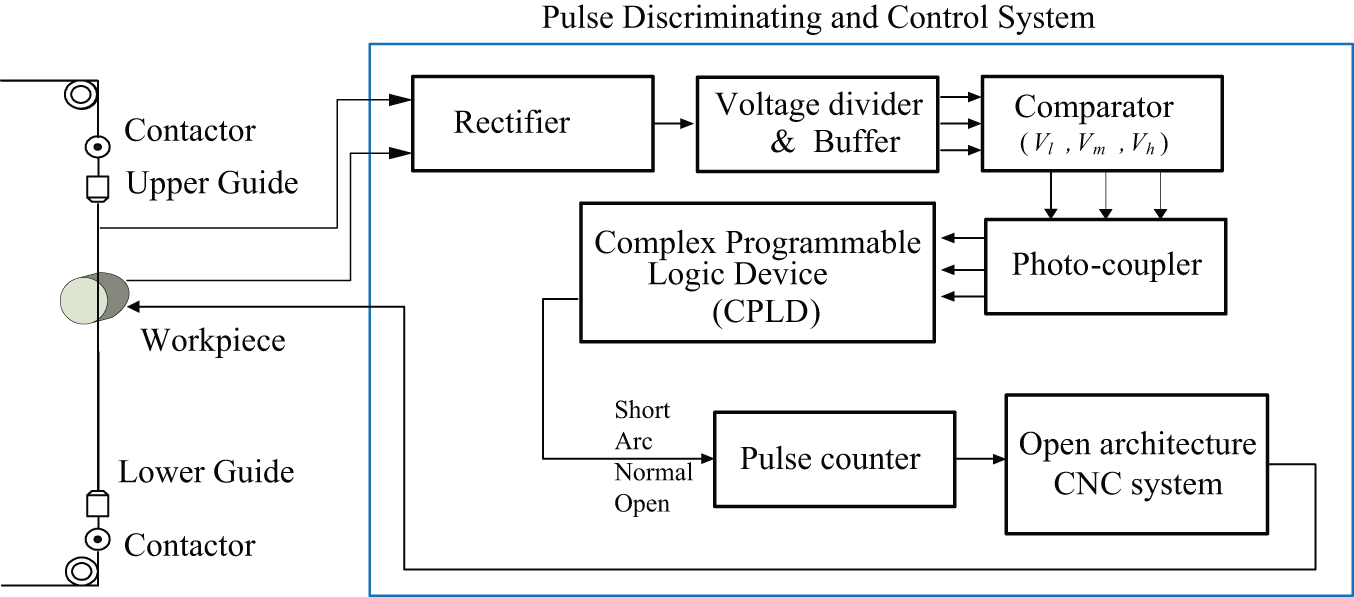
A novel pulse discriminating and monitoring system for wire-EDM process.
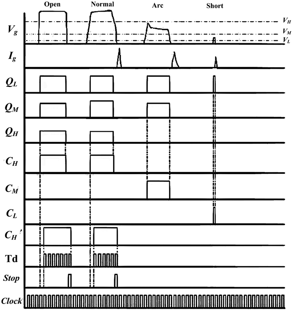
Timing chart of the pulse discriminating signals.
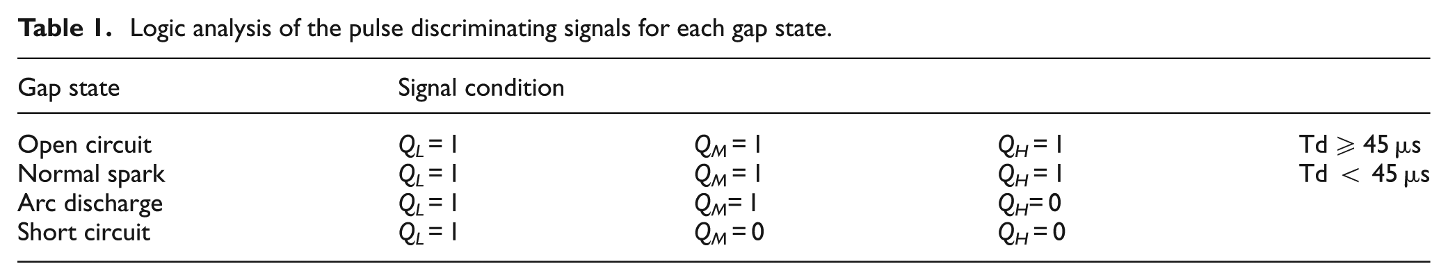
Logic analysis of the pulse discriminating signals for each gap state.
A digital signal processor (DSP) card (VP2812EVM evaluation board) was employed to compute ignition delay time for each spark as well as identify four gap states, that is, open circuit, normal spark, arc discharge and short circuit, according to the output states of three comparators and the duration of ignition delay time. The DSP card was chosen for its cost-effectiveness and easy modification purpose. The VP2812EVM evaluation board is featured with TMS320F2812 DSP, 33 MHz clock rate, 150 millions of instructions per second (MIPS) operating speed and stand-alone execution function. An open-architecture computer numerical control (CNC) system developed by our previous study was used for data transfer, pulse train analysis and user interface. 19 The DSP card can transfer data to the open-architecture CNC system through an RS232 interface with a baud rate of 9600 bps. A user interface was designed under the integrated development environment of Borland C++ Builder 5.0 featured with object-orientation and component-oriented philosophy of C++. By means of the discrimination system, the proportion of open circuit, normal spark, arc discharge and short circuit to total sparks (defined as open circuit ratio, normal spark ratio, arc discharge ratio and short circuit ratio, respectively) and ignition delay time (Td) within a time interval of 100 ms can be on-line detected and analyzed.
Experimental method
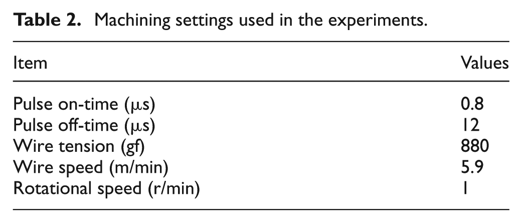
An numerical control (NC) rotary indexing table (TOPSDISK TD125) has been added to a flushing-type wire-EDM machine (JSEDM type W-A30) so as to produce cylindrical forms and three-dimensional parts such as screw, drill and ball components. The rotary indexing table has the following features: high mechanical efficiency of power transmission, high indexing accuracy and high repeatability accuracy, and therefore, it was integrated into the commercial wire-EDM machine to meet the requirement of high rotation accuracy, high current electrical connectivity to the ground and effective shield against electromagnetic interference. Since some components of the rotary table were not made of water corrosion–resistant materials, it needs to be protected against spraying during machining. The wire-EDM machine comprises an anti-electrolysis power supply system, a dielectric generation system, a PC–based controller with proprietary CNC architecture, a five-axis ball-screw drive alternating current (AC) motor system and a flushing device. To perform synchronous motion control between the rotary axis and the translational axis for thread cutting using WEDT, the open-architecture CNC system developed by our previous study 17 has been implemented in the wire-EDM machine in substitution for the proprietary CNC. Two types of motion control for the rotary table can be provided by the open-architecture CNC system. One is asynchronous motion control between the rotary axis and the translational axis that can facilitate the wire-EDM machine to fulfill the task of CWEDT, and the other is synchronous motion control between the rotary axis and the translational axis that can enable the wire-EDM machine to perform the function of thread cutting using WEDT. Figure 4 shows illustrations of the CWEDT process and thread cutting using WEDT. Copper wire with a diameter of 0.25 mm and SKD11 tool steel bars with a diameter of 20 mm were used for the electrode and the workpiece, respectively. The rotary indexing table can provide a maximum rotational speed of 5 r/min. Machining settings used in the experiments are given in Table 2. Figure 5 shows a rotary table in a wire-EDM machine, a rod component and a screw fabricated by the experimental setup. Apparently, the rod and screw components as shown in Figure 5(b) and (c) were manufactured by means of the CWEDT process and a thread cutting operation using WEDT, respectively. As it can be seen from Figure 5(b) and (c), NC programs for the CWEDT and the thread cutting operation using WEDT demonstrate that the translational axis (X-axis) moves independently and synchronously with the rotary axis (W-axis). The developed pulse discriminating system has been integrated with the open-architecture CNC system for the sake of on-line monitoring of the WEDT process.
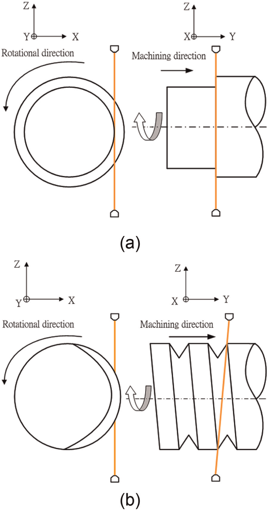
Illustrations of (a) the CWEDT process and (b) thread cutting using WEDT.
Machining settings used in the experiments.
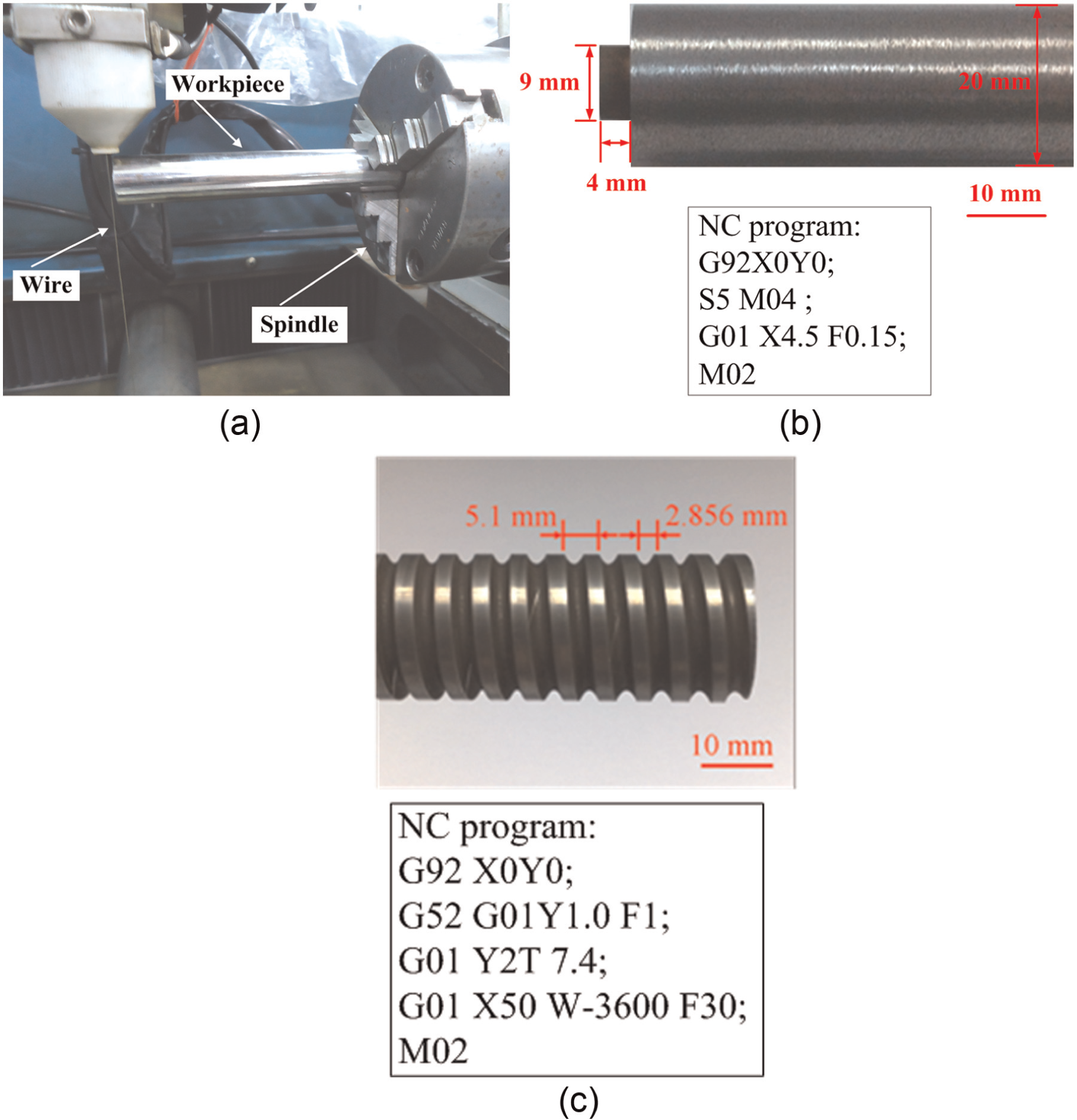
(a) An NC rotary indexing table in a wire-EDM machine, (b) a rod component and (c) a screw fabricated by the experimental setup.
Experimental results and discussion
To verify the effectiveness of the pulse discriminating system, several experiments were conducted by means of CWEDT and thread cutting using WEDT. Figure 6 shows the time evolution of gap voltage, table feedrate, the proportion of open circuit, normal spark, arc discharge and short circuit to total sparks and ignition delay time under a servo feed control condition during the CWEDT process, which means that table feedrates for the translational axis were adjusted by servo feed control and rotational speed of the rotary axis was constant during the machining process. The servo reference voltage was set as 76 V. It can be observed from Figure 6 that these measured data exhibited an oscillation with almost a fixed time period, and the time period of the oscillation was measured as 125 s. It can also be noted that the pulse train data and ignition delay time, as shown in Figure 6(c) and (d), demonstrated much more clear information than average gap voltage for monitoring the CWEDT process partly because the sensing equipment of the servo feed control system in a commercial wire-EDM machine was susceptible to electromagnetic interference. In this study, the roundness of a cylindrical part is defined as the difference between the largest radius and the smallest radius of the cross-sectional view. The radius error of the cylindrical part used in this experiment is 0.12 mm. This oscillation phenomenon might result from the poor roundness of the cylindrical part or the instability of the servo feed control system during the CWEDT process. This assumption has to be confirmed by the following experiments and analysis.
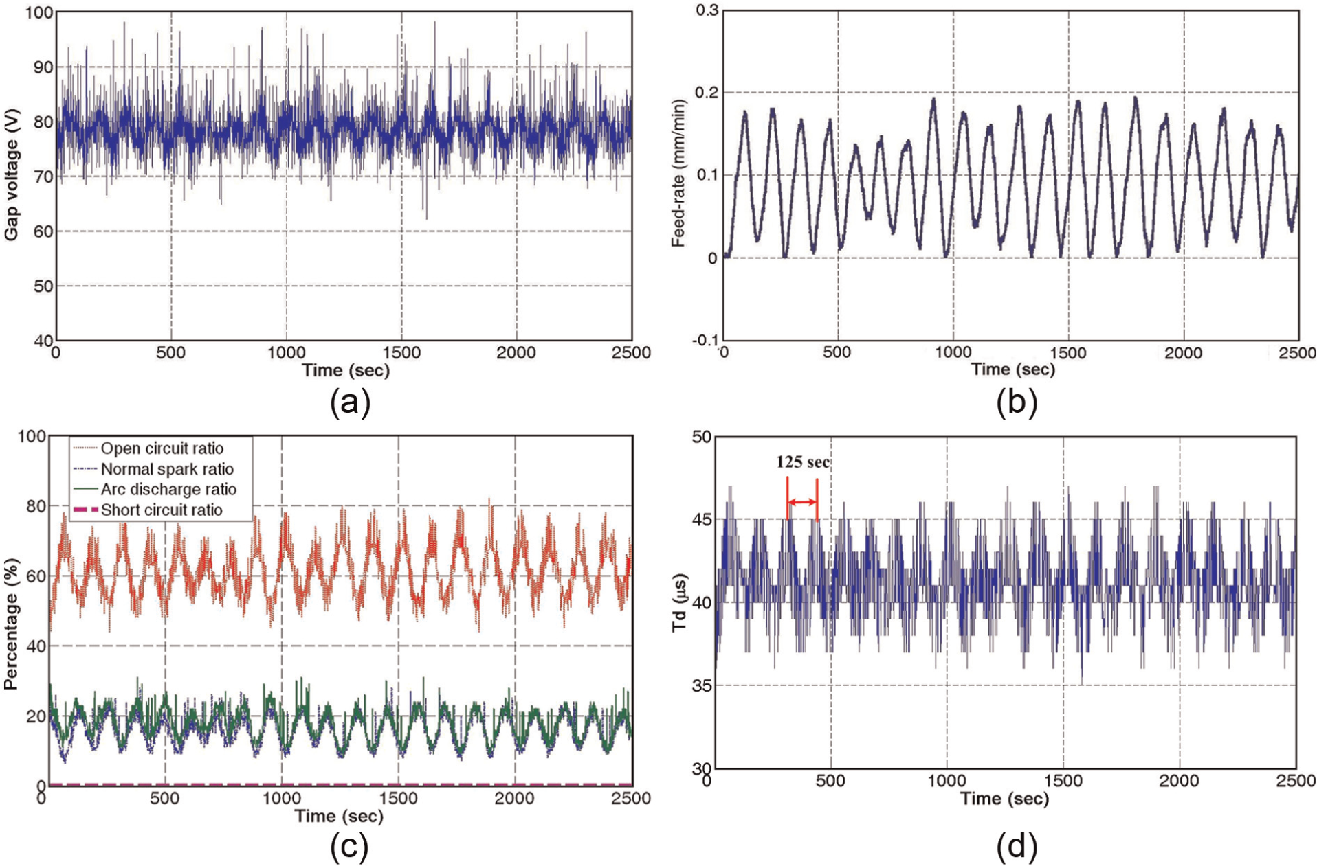
Time evolution of (a) gap voltage, (b) table feedrate, (c) the proportion of open circuit, normal spark, arc discharge and short circuit to total sparks and (d) ignition delay time under a servo feed control condition during the CWEDT process.
A cylindrical part with a radius error of 0.92 mm was machined by CWEDT to investigate the effect of the poor roundness of the cylindrical part on the time evolution of pulse train data. Figure 7 shows the time evolution of gap voltage, the proportion of open circuit, normal spark, arc discharge and short circuit to total sparks and ignition delay time under a constant feedrate machining condition during the CWEDT process. The feedrate setting is 0.1 mm/min, and the spindle rotational speed is 1 r/min. It can be clearly found from this figure that these measured data presented an oscillation with a time period of 65 s. This oscillation period is closely related to the rotational speed. Under a constant feedrate machining condition, a poor roundness of the cylindrical part led to the oscillatory phenomenon of the measured data in which its oscillation period relied heavily on the rotational speed.
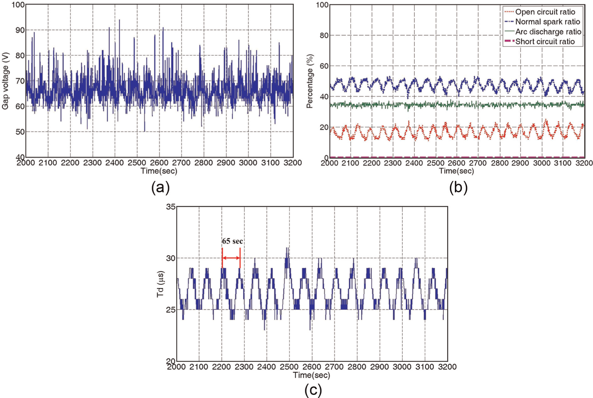
Time evolution of (a) gap voltage, (b) the proportion of open circuit, normal spark, arc discharge and short circuit to total sparks and (c) ignition delay time under a constant feedrate machining condition during the CWEDT process.
To examine the effect of servo feed control on the time evolution of pulse train data, the cylindrical part, the same as that used in Figure 6, was machined for thread cutting using WEDT, which means synchronous motion control between the rotary axis and the translational axis. Figure 8 shows the time evolution of gap voltage, table feedrate, proportion of open circuit, normal spark, arc discharge and short circuit to total sparks and ignition delay time under a servo feed control condition during a thread cutting operation using WEDT. The servo reference voltage was set as 68 V. It can be seen from this figure that these measured data displayed steady states after a transient period of 100 s. The proportion of open circuit, normal spark, arc discharge and short circuit to total sparks and ignition delay time, as shown in Figure 8(c) and (d), shows more clear results without containing any high-frequency noises compared with that of gap voltage, as shown in Figure 8(a). Apparently, no oscillation phenomenon similar to that as shown in Figure 6 can be found in this experiment.
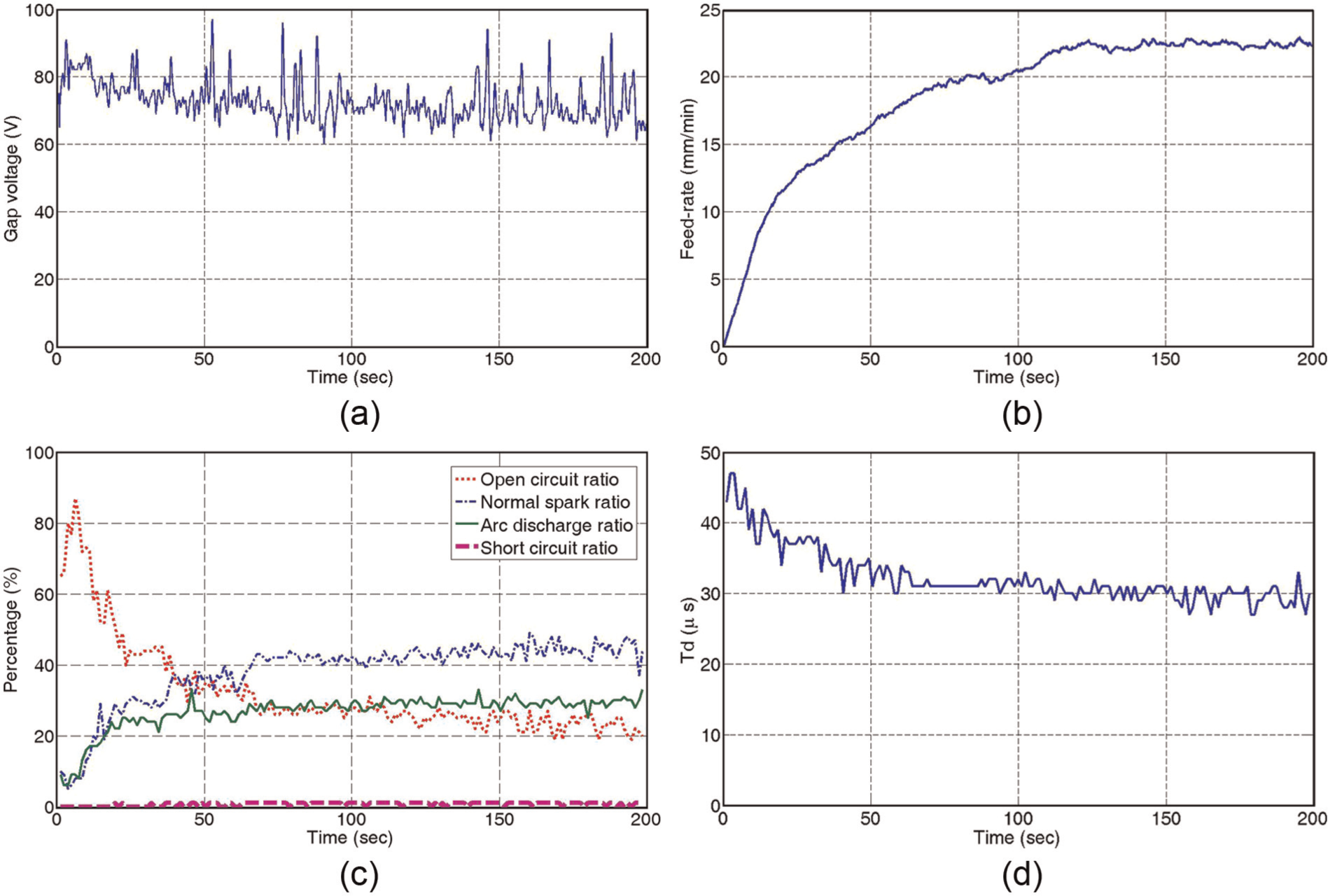
Time evolution of (a) gap voltage, (b) table feedrate, (c) the proportion of open circuit, normal spark, arc discharge and short circuit to total sparks and (d) ignition delay time under a servo feed control condition during a thread cutting operation using WEDT.
As can be seen from Figure 7, the oscillation phenomenon arisen from poor roundness of the cylindrical parts demonstrated an oscillatory period closely related to the rotational speed. Therefore, the oscillation phenomenon, which occurred in the case of Figure 6, might be attributable to servo feed control during the CWEDT process. Figure 9 shows schematic diagrams of spark gap during the CWEDT process and thread cutting using WEDT. During the CWEDT process, as illustrated in Figure 9(a), the rotary spindle moves independently with the translational axis, and thus, table feedrate was adjusted by servo feed control to keep forward sparking gap in the wire transverse direction at a proper width. The conventional servo feed control system used average gap voltage as the only feedback signal to adjust the gap distance between the workpiece and the wire electrode by controlling the table feedrate. The average gap voltage that takes the average voltage of pulse trains, however, was not a good indicator to promptly reflect stochastic nature and process dynamics at the spark gap for the CWEDT process. The rotary motion with a fixed speed continuously changed lateral gap width during the CWEDT process, but average gap voltage could not reveal the subtle change in spark gap states. As the spindle rotates during machining, the change in lateral gap width could be regarded as an unexpected disturbance for the servo feed control system. Therefore, the conventional gap voltage control system could not react properly to the variation of lateral gap width during the CWEDT process by only controlling the table feedrate in the translational axis. On the other hand, during thread cutting using WEDT as shown in Figure 9(b), the open-architecture CNC system could provide synchronous motion control between the rotary axis and the translational axis, and therefore, the servo feed control system could respond to the change in spark gap condition by adjusting table feedrate for the translational axis and rotational speed for the rotary axis simultaneously. Nevertheless, spark gap was commonly contaminated by removed particles or debris under a high feedrate machining condition for the WEDT process, particularly in the case of a flushing-type wire-EDM machine. Under such poor flushing condition, arc discharges and short circuits occurred frequently due to the contamination of spark gap. Average gap voltage often failed to indicate the change in spark gap condition because of the average effect of pulse train data.

Schematic diagram of spark gap during (a) the CWEDT process and (b) thread cutting using WEDT.
Conclusion
In this article, a pulse discriminating and monitoring system has been devised for the identification of gap states, on-line quantitative pulse train analysis and machining condition monitoring. This study has suggested that conventional servo feed control system cannot respond instantaneously to the variation of lateral gap width caused by an asynchronous motion between the rotary axis and the translational axis during the CWEDT process because average gap voltage cannot provide real-time knowledge of the behavior of the discharges in the spark gap. Experimental results also demonstrate that the developed pulse discrimination system can provide more clear information (i.e. the proportion of open circuit, normal spark, arc discharge and short circuit to the total sparks and ignition delay time) than average gap voltage for on-line evaluation of the spark gap condition during the WEDT process.
Based on the developed system, a research on adaptive process control of WEDT using arc discharge ratio and ignition delay time as feedback signals for the purpose of improving machining stability and efficiency is continuing in our laboratory.
Footnotes
Declaration of conflicting interests
The authors declare that there is no conflict of interest.
Funding
This research was supported by the Ministry of Science and Technology, Taiwan, under grant no. NSC 102-2221-E-211-004-MY2.