
Abstract
Drilling is an indispensable machining operation, which is mostly performed for making holes in an intricate composite part. In this research investigation, a finite element model has been developed to simulate the drilling behavior of Al1100/10% SiC metal matrix composite using finite element platform (ABAQUS/Explicit). The effect of cutting speed and feed rate on thrust force has also been experimentally evaluated. It was found that the magnitude of thrust force obtained from the proposed finite element model is in close agreement with the experimental values. It was also established that the proposed finite element model is quite efficient to predict the thrust force signals generated during drilling of metal matrix composites.
Introduction
Metal matrix composites (MMCs) have distinct characteristics, such as lightweight, high specific strength and stiffness, high fracture toughness, high temperature, as well as wear resistance.1,2 Due to superior mechanical properties, MMCs are finding widespread applications in various engineering fields. For the assembly of several MMC components together or with other materials, drilling is repeatedly performed on MMC parts. But drilling of MMCs is somewhat difficult because the hard reinforcement particles present in MMCs make it a challenging task.3,4 For instance, during drilling of Al/SiC MMCs, when the tool cutting surface comes in contact with hard SiC particles, the SiC particle acts as small cutting edge, which results in rapid tool wear, poor surface finish, high drilling forces, and burr formation. 5 It has been established that the drilling forces and the average surface roughness of the Al2O3-filled aluminum-based MMCs are greatly influenced by the feed rate and the cutting speed. 6 Furthermore, feed rate is also accountable for tool wear response. Lower feed rate resulted in higher flank wear because the contact time between the tool and the workpiece is higher at low feed rate. This means rubbing of tool against hard reinforcement particles is more, which results in greater flank wear. In addition to tool wear, the drilling-induced thrust force and torque are also significantly influenced by the feed rate. The drilling-induced forces were found to increase with an increase in feed rate. 7 On the other hand, the surface roughness of the machined surface was found to increase with an increase in feed rate and decrease with an increase in the cutting speed. The formation of built-up edges on the tip of the drill is also predominant by increasing feed rate, which resulted in higher surface roughness. The formation of burrs at entry and exit sides of the hole is one of the major problem associated with the drilling of MMCs. Burr formation during drilling eventually affects the functional characteristic of the MMCs. Burr height that is usually measured to define the burr formation characteristics was found to increase predominantly with an increase in the feed rate and decrease with an increase in the cutting speed. 5 From the discussion, it is quite clear that the feed rate and the cutting speed are the influential parameters that determine the machinability of MMCs.
The literature available till date mostly concentrated on the experimental investigation and statistical analysis of various parameters during drilling of MMCs. As the properties of the MMCs change with the variation in the type, shape, size, and amount of the reinforcement particles, it is difficult to optimize the process parameters for high-quality holes in MMCs. Therefore, it becomes imperative to develop a generic finite element (FE) model (validated with experimental results) to predict the drilling behavior of MMCs. The research efforts put toward the development of FE model for predicting the thrust force during drilling of MMCs are very rare. The thrust force generated during drilling is an important aspect as it mostly defines the quality of the drilled hole in terms of burr formation. Therefore, this research initiative is an attempt to propose an FE model for predicting the signal and magnitude of thrust force generated during the drilling of Al1100/SiC MMCs.
FE model for drilling process
The most commonly used constitutive model that describes the flow stress during machining was proposed by Johnson–Cook. In this model, the flow stress depends on the strain, strain rate, and temperature effects. The same mathematical model was used in the proposed FE model using FE-based simulation software (ABAQUS/Explicit). The Johnson–Cook constitutive equation can be represented by equation (1)
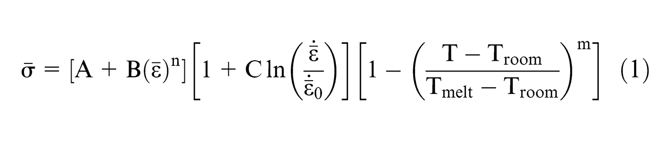
where
Johnson–Cook parameters. 8

The failure of the work material during machining can be predicted using Johnson–Cook fracture model. In this fracture model, the failure criterion is based on equivalent plastic strain. The equivalent plastic stain at fracture is determined using Johnson–Cook fracture model and can be represented by equation (2)
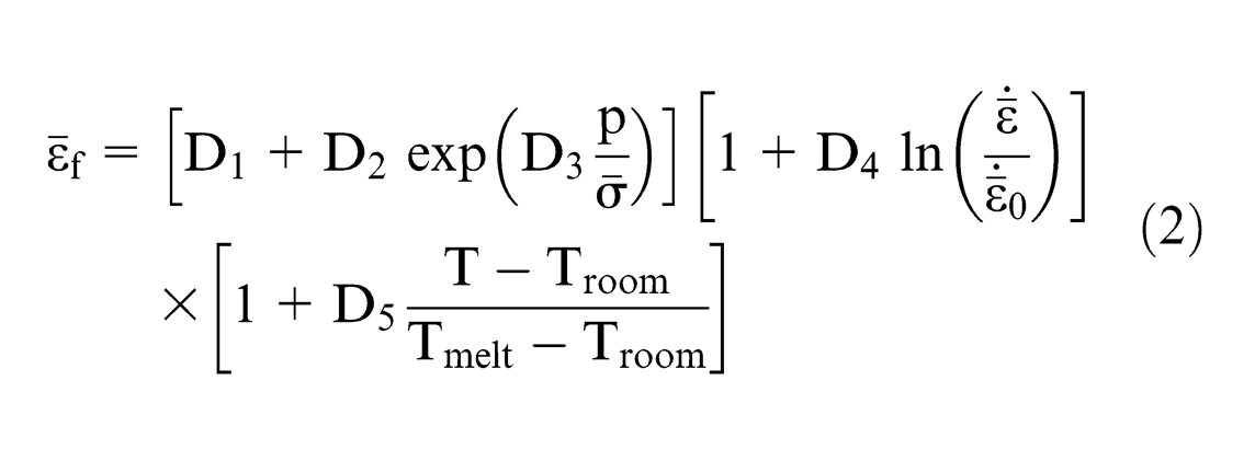
where p is the hydrostatic pressure,
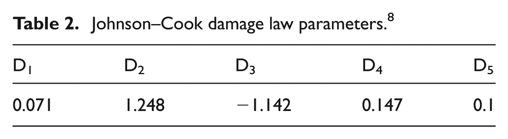
The values of damage law parameters (D1–D5) and properties of the material considered for the proposed model are presented in Tables 2 and 3, respectively.
Johnson–Cook damage law parameters. 8
Properties of the materials. 8
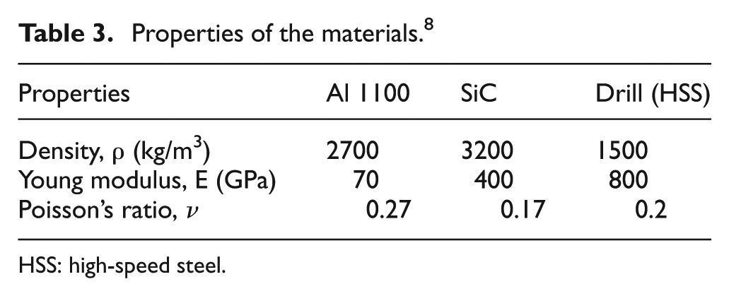
HSS: high-speed steel.
Damage evolution law can be specified either in terms of fracture energy or equivalent plastic displacement. Both approaches take into account the characteristic length of the element. In the present FE model, a choice has been incorporated in order to remove the element from the mesh using an equivalent plastic displacement (displacement at failure is 0.0001 mm). Damage evaluation describes the rate of degradation of the material stiffness once the initiation criterion is satisfied. The formula is based on scalar damage approach as given by equation (3)

where
In the present model, C3D8R elements have been used. For modeling of drill, helix angle of 30°, lip relief angle of 7°, and point angle of 118° have been considered. For the present FE model of drilling process, it is mandatory to fix the workpiece (i.e. Encastre U1 = U2 = U3 = UR1 = UR2 = UR3 = 0). For the drill, displacement/rotation, velocity/angular velocity-type boundary conditions have been applied. The response of work material during drilling is shown in Figure 1.
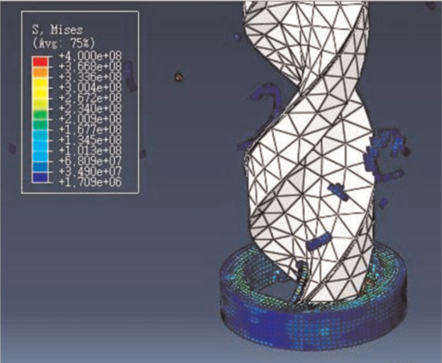
Material response during drilling.
The development of an accurate and sound continuum-based FE model is always anticipated in order to study the influence of various process parameters on output responses. In many nonlinear simulations, the material in the structure or process undergoes very large deformation. The large deformation of material may distort the FE mesh, often to the point where the mesh is unable to provide accurate results or the analysis terminates for numerical reasons. In such simulation, it is necessary to use adaptive meshing tool to periodically minimize the distortion in the mesh. ABAQUS/Explicit provides a robust adaptive meshing capability for highly nonlinear problems ranging from quasi-static to high-rate dynamic. In this work, adaptive meshing is performed in ABAQUS/Explicit using arbitrary Langrangian–Eulerian (ALE) technique to conduct the FE simulation and all the attributes have been successfully implemented in the simulation model. It was found that with the use of adaptive meshing, the proposed FE model predicted closer values to the experimental findings and also helped to model the transient phase of the process. Many techniques such as adaptive meshing, mass scaling, and visualization functionality have been introduced to make the model highly accurate and to get better results. Adaptive meshing technique also helps to improve the mesh quality. Improving mesh quality increases the stable time increment size, which makes up for the added cost of the adaptive mesh increment. Mass scaling helps to reduce time running process of calculation work. It is generally desirable to analyze a model in its natural time period if rate dependency is being considered. But the proposed FE model utilized a semi-automatic mass scaling by specifying target time increment. Visualization functionality in ABAQUS/Viewer has also been extended to visualize preprocessing modeling entities, such as interactions, pre-defined fields, and loads.
Experimental procedure
Chemical grade SiC with more than 99.5% purity and aluminum alloy Al1100 were used as reinforcement and matrix, respectively. The MMC was fabricated in-house using a standard manufacturing process called stir and squeeze casting. The average particle size of 10 µm and weight percentage of 10% of SiC were used for the development of MMCs. The dry drilling tests were conducted on MMC plate of thickness of 6 mm using radial drilling machine at various combinations of cutting speeds (900, 1800, and 2700 r/min) and feed rates (0.12, 0.18, and 0.3 mm/rev). High-speed steel (HSS) drill of 8 mm diameter was selected for drilling operation. Four-component dynamometer (KISTLER, type: 9272) was used to measure the thrust force. The dynamometer was connected to the personal computer (PC) via analog-to-digital converter card and the force signals were recorded online in the PC using Dynoware software. A high sampling rate was selected so as to record each and every minor variation in the drilling force. Each experimental run was conducted at least three times in order to nullify any random variation in the recorded value.
Results and discussion
During the drilling of developed MMCs, the thrust force signals were recorded at various combinations of cutting speed and feed rate. The thrust force signals obtained from FE model at various cutting speeds are shown in Figure 2. A typical thrust force signal as a function of drilling time as predicted by the developed FE model and the one recorded experimentally using the four-component drill dynamometer is shown in Figure 3. From the figure, it is quite clear that the thrust force signal predicted by the FE model follows the trend of experimental thrust force signal with fair degree of accuracy. Therefore, it is evident that the developed FE model is quite efficient to predict the thrust force signal. But it is worth mentioning that in the case of experimental thrust force signal, the fluctuation in thrust force is quite high as compared to the signals obtained from FE model. The resulted fluctuations in the thrust force may be attributed to the random distribution of small reinforcement (SiC) particles in the aluminum matrix. Based on the thrust force signal, the complete drilling operation can be divided into four stages as indicated in Figure 3 (Stage 1: A–B, Stage 2: B–C, Stage 3: C–D, and Stage 4: D–E). From the figure, it is clear that in Stage 1, thrust force value increases abruptly till the complete engagement of the cutting lips with the composite plate takes place. In Stage 2, complete engagement of drill takes place, which results in almost constant value of thrust force. At Stage 3, thrust force decreases rapidly because at this stage, drill tip exits the composite plate, whereas in Stage 4, the magnitude of thrust force becomes 0 due to the complete exit of cutting lips of the drill.
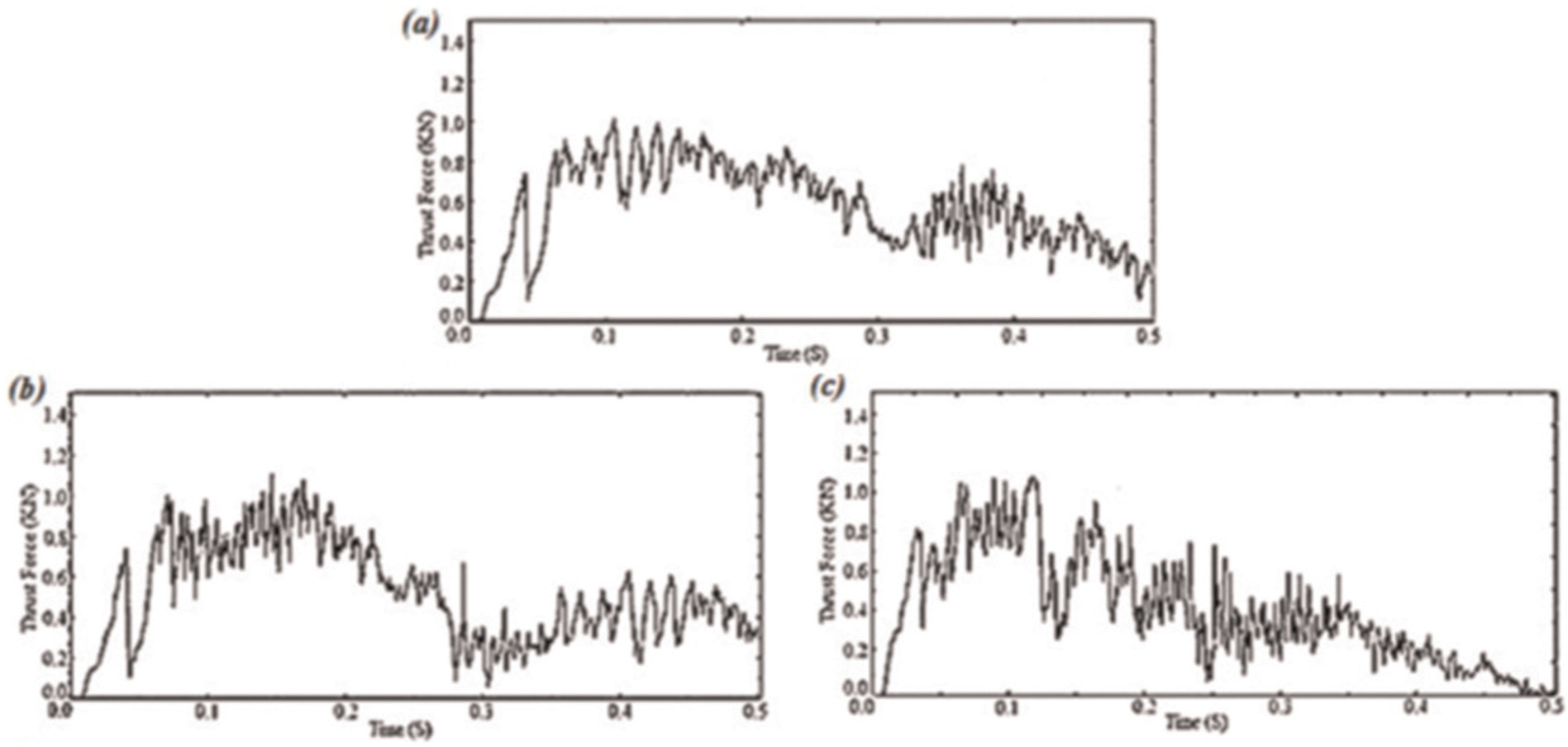
Simulated thrust force signals at feed rate of 0.18 mm/rev and spindle speed of (a) 900, (b) 1800, and (c) 2700 r/min.
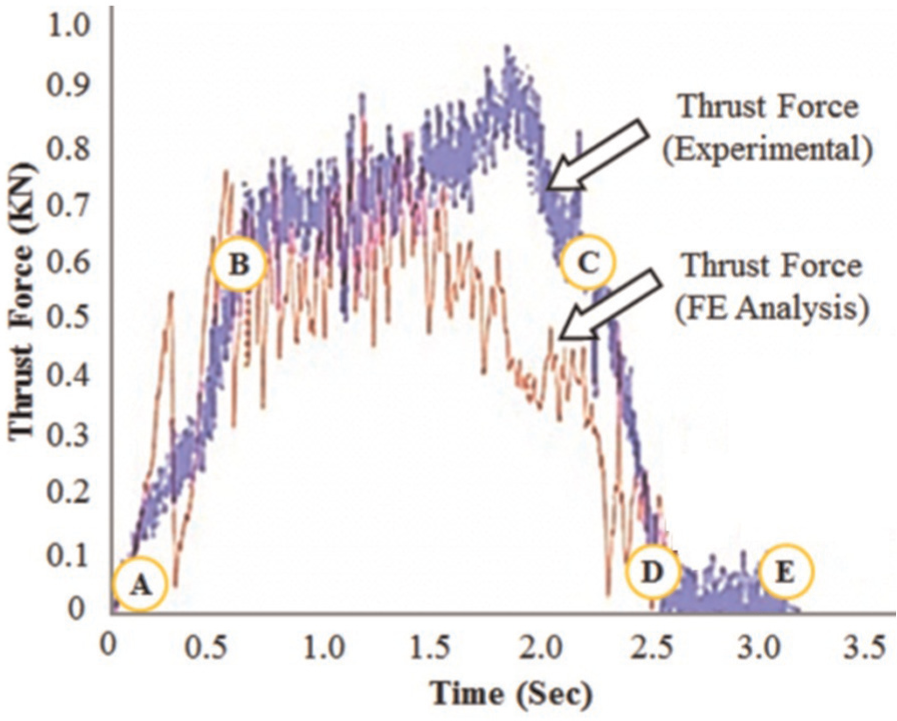
Thrust force signal for cutting speed of 2700 r/min and feed rate of 0.12 mm/rev (predicted and experimental).
The thrust force values recorded during experiments and predicted by the FE model are shown in Figure 4. It is quite clear from the figure that the proposed FE model predicts the thrust force in a reasonable manner. From the simulation results, it was found that the thrust force increases linearly with an increase in the level of cutting speed and feed rate, whereas some aberrations were observed in the experimental values of thrust force. The plausible reason for such behavior of experimental thrust force is the presence of manufacturing defects or voids in the developed MMCs. The lower values of the thrust force as predicted by the FE model may be attributed to the tool wear effect. HSS was the tool material used for experimentation, whereas a rigid tool material was selected for FE model. Basavarajappa et al. 9 have also reported that as the feed rate and cutting speed increase, the thrust force increases during drilling of hybrid MMCs. It has also been observed that the thrust force is significantly influenced by the feed rate than the cutting speed. The FE model estimated the thrust force between 814 and 1087 N for the range of feed rates and cutting speeds modeled. For a cutting speed of 1800 r/min when feed rate was increased from 0.12 to 0.18 and 0.30 mm/rev, the thrust force increased by 24% and 29%, respectively. The results reveal that the percentage error between the predicted and experimental values lies in between 3.36% and 14.76%, respectively. The percentage error in the results can be further minimized by introducing the effect of tool wear, temperature effects, more realistic friction and damage model, and other type of elements to discretize the MMC plate.
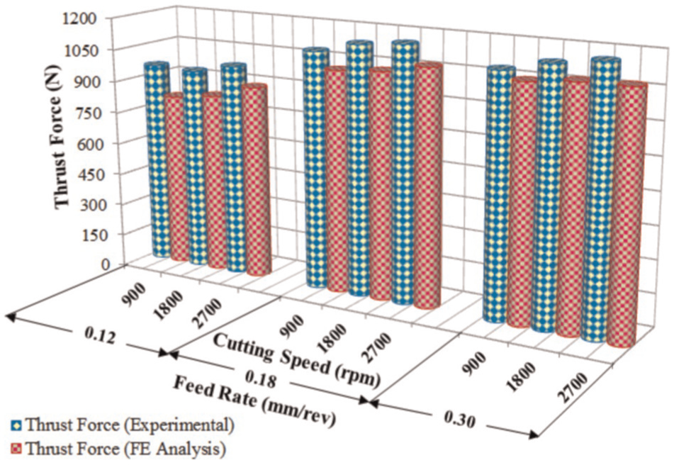
Comparison between experimental and FE model results.
Conclusion
In the present research endeavor, a three-dimensional FE model has been proposed for predicting the thrust force during drilling of MMCs. The results predicted by the model have been compared with experimental results. Based on the results obtained from developed FE model, it can be said that element deletion and adaptive meshing technique provides more realistic results. The comparison of the experimental and the simulation results was undertaken and a close agreement was found. It was found that the proposed FE model is quite efficient to predict the thrust force response generated during drilling of MMCs. It was also experimentally found that the thrust force increases with an increase in cutting speed and feed rate. Therefore, low cutting speed and feed rate should be preferred while drilling Al1100/10% SiC MMCs. The FE model can be further updated by incorporating the effect of tool wear, tool–workpiece temperature, and more realistic friction and damage model.
Footnotes
Declaration of conflicting interests
The authors declare that there is no conflict of interest.
Funding
This research received no specific grant from any funding agency in the public, commercial, or not-for-profit sectors.