
Abstract
Magnetic field assisted powder mixed electrical discharge machining is a hybrid machining process with suitable modification in electrical discharge machining combining the use of magnetic field and fine powder in the dielectric fluid. Aluminum 6061 alloy has found highly significance for the advanced industries like automotive, aerospace, electrical, marine, food processing and chemical due to good corrosion resistance, high strength-to-weight ratio, ease of weldability. In this present work, magnetic field assisted powder mixed electrical discharge machining setup was fabricated and experiments were performed using one factor at a time approach for aluminum 6061 alloy. The individual effect of machining parameters namely, peak current, pulse on time, pulse off time, powder concentration and magnetic field on material removal rate and tool wear rate was investigated. The effect of peak current was found to be dominant on material removal rate and tool wear rate followed by pulse on time, powder concentration and magnetic field. Increase in material removal rate and tool wear rate was observed with increase in peak current, pulse on time and a decrease in pulse off time, whereas, for material removal rate increases and tool wear rate decreases up to the certain value and follow the reverse trend with an increase in powder concentration. Material removal rate was increased and tool wear rate was decreased with increase in magnetic field.
Keywords
Introduction
Electrical discharge machining (EDM) process is non-conventional machining process where the material is removed by melting and vaporization for generating complex profiles.1,2 Over the past few decades, EDM process was used for tool and die making but in recent times it has been found in industrial applications including aerospace, automobile, military industry and surgical instruments making.3–5 Low machining efficiency and high surface roughness limit the use of EDM process for large-scale production. Moreover, subsurface defects such as spalling, cracks, residual stress, porosity, heat-affected zone and metallurgical transformations occur in EDM process due to the rapid high-temperature melting and cooling during the process on machining of workpiece.6,7 Thus, to improve the machining rate, surface finish as well as to minimize the surface detects, magnetic field (MF) assisted powder mixed electrical discharge machining (MFAPMEDM) can be utilized successfully for machining of hard and conductive materials. In this process, conductive powder is mixed in a dielectric fluid and in the presence of MF coupled with electric field producing a Lorentz force which assists the removal of material. 8 MFAPMEDM is a process which is capable of machining the complex profile on the workpiece with better surface finish and accuracy and having burr-free surface. This technology is found application in the field of manufacturing of surgical instruments, automobile parts, dies, military parts and aerospace components. 9
Aluminum (Al) 6061 alloy is widely used for various industrial as well as engineering applications such as aerospace, automobile, marine and aircraft industries due to its specific properties such as high corrosion resistance, toughness, good ductility, ease weldability and high strength-to-weight ratio.10–12 Most of the researchers possess difficulties such as the formation of a built-up layer on the rake surface that seizes the tool tip causing geometrical inaccuracy, poor surface quality, burr formation on the machining by the conventional process. 13 To overcome these difficulties, advanced machining processes such as abrasive water jet (AWJ), laser beam machining (LBM), electrochemical machining (ECM) and EDM can be utilized for machining of Al 6061 alloy. Over these advanced machining processes, one can opt MFAPMEDM for machining Al 6061 alloy due to enhanced productivity, better surface quality, minimal recast layer and high accuracy.
Bhattacharya et al. 14 performed machining on AISI D2, AISI D3 and H13 steel using tungsten and titanium powder mixed under the influence of MF. The effect of machining parameters on microstructure was analyzed and increase in microhardness was observed. Kant 15 explored the machinability of an EN-19 tool with graphite powder mixed in a dielectric fluid under the influence of MF. U-shaped copper electrode was used for machining and investigation was measured in terms of overcut, material removal rate (MRR) and surface roughness. It was noted that graphite powder with concentration at 2 g/L along with tool as copper gives better results for performance measures. However, minimum overcut was observed at higher pulse duration and MF. Bhatt et al. 8 machined the different grades of steel such as AISI D2, AISI D3 and H13 steel using titanium, tungsten and graphite powder suspended in EDM oil along with the MF. The influence of process parameters on performance characteristics such as surface roughness, overcut, microhardness, MRR and tool wear rate (TWR) was explored and current was the most observed as significant parameters. Singh and Yeh 16 studied the machinability of aluminum matrix composites with abrasive powder mixed in a dielectric fluid and noted pulse on time as an influential parameter. Multi-objective optimization was performed using Taguchi and gray relational analysis method to obtain optimal solutions. Talla et al. 3 explored the machinability of aluminum/alumina metal matrix composites (MMC) in powder mixed EDM and developed the empirical model to predict the MRR and surface roughness. The optimum set of process parameters for surface roughness and MRR was obtained using gray relational analysis. Lin and Lee 17 studied the influence of process parameters on machining of SKD-61 steel in MF assisted EDM and optimization was performed using gray relational analysis for optimum parameters. Heinz et al. 18 machined Titanium alloy by orienting the Lorentz force generated as result of an electric and MF in the direction of workpiece surface in MF assisted micro EDM. However, 50% increase in material removal and 54% increase in erosion efficiency was observed during the machining process.
From the intensive scrutiny of the literature, it has been observed that most of the researchers have been studied on the influence of the MF assisted or powder mixed EDM process. Very few works have been published on the combined effect of magnetic and power assisted EDM. The newly fabricated MFAPMEDM setup mechanism has been studied. Machining of Al 6061 alloy was performed successfully. The individual effect of machining parameters such as peak current (IP), pulse on time (TON), pulse off time (TOFF), powder concentration (PC) and MF on responses TWR and MRR has been studied.
Fabrication of MFAPMEDM setup
Considering the fundamental mechanism of the MFAPMEDM process and functional requirement of different components with consideration of weight and vibration, the attachment of MFAPMEDM setup has been designed and fabricated. The fabricated attachment has been fitted on the Die-Sinker EDM machine (EMS-5030) make Elektra and also the actual tool holder is replaced with fabricated for easy holding of tool electrode of variable diameter on die-sinking EDM and was also tested successfully. The pilot test experiments were successfully conducted to decide the range of machining parameters applicable for performance characteristics of the MFAPMEDM process.
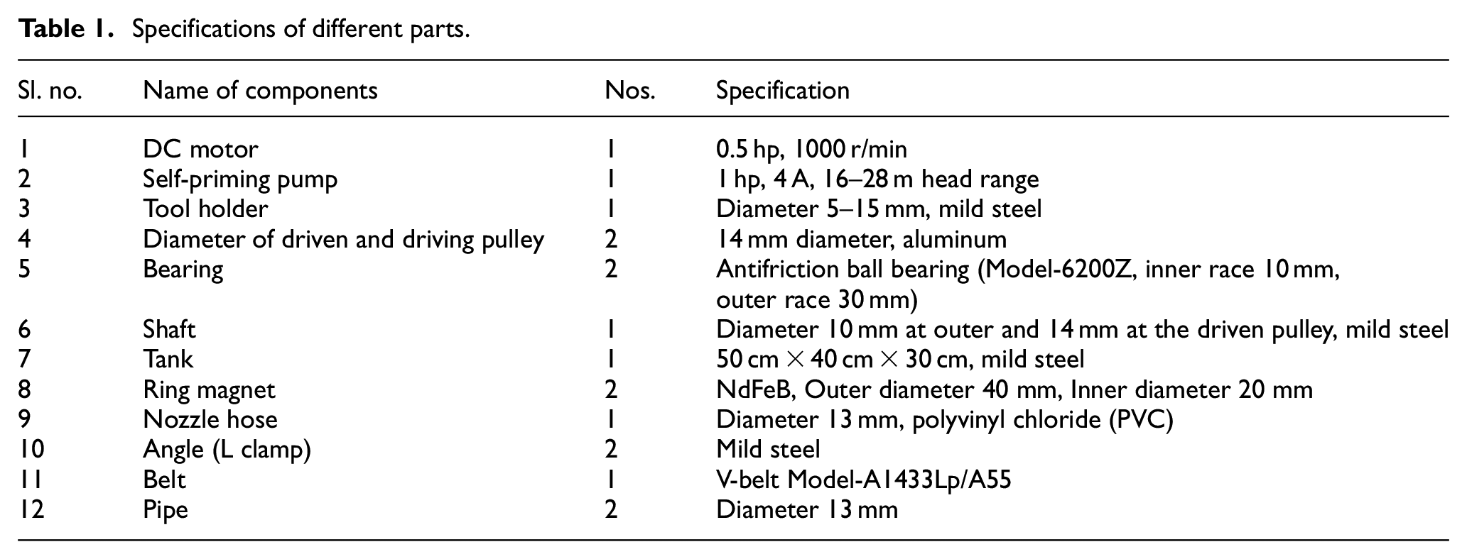
The experimental setup for the MFAPMEDM consists of six components namely, (a) dielectric circulation system, (b) power supply system, (c) positioning system, (d) servo-controlled feed system, (e) stirring system and (f) MF system. The specification of components used in the fabrication of setup is depicted in Table 1. Dielectric circulation system consists of self-priming pump is coupled with pipe and nozzle hose made of PVC, which flushes the dielectric fluid through the inter electrode gap zone between the tool electrode and the workpiece removing the machined debris particles to achieve closer tolerance and better surface quality. It also maintains the uniform distribution of mixed powder particles in the dielectric fluid using circulation cycle capability. The power supply system consists of an electrical circuit that generates a power pulse and time control function device that controls the amount of current required to flow each power pulse. The power supply system is also known as the mother of the system as it supplies pulses at a certain current, pulse on time and voltage consistently and repeatedly to its electrical circuits. The servo-controlled feed system maintains the optimum spark gap between the workpiece and the tool electrode to ensure the active discharge during machining. The stirring system consists of DC motor coupled driving pulley made of aluminum with stir attachment made of mild steel along with driven pulley along with the belt drive system to ensure that the powder mixed with dielectric fluid does not get settled at the bottom of the tank. MF system consists of two neodymium ring magnets placed on the side of workpiece material as denoted by the MF as shown in Figure 1. Schematic diagram and actual fabricated model of the MFAPMEDM setup are depicted in Figures 2 and 3(a) and (b).
Specifications of different parts.
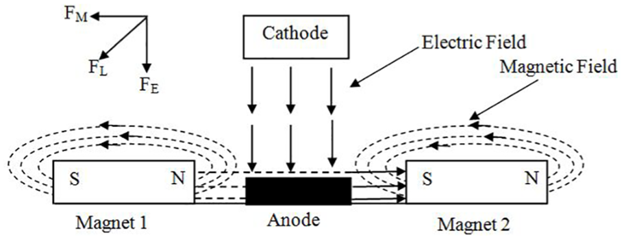
Magnetic field system.
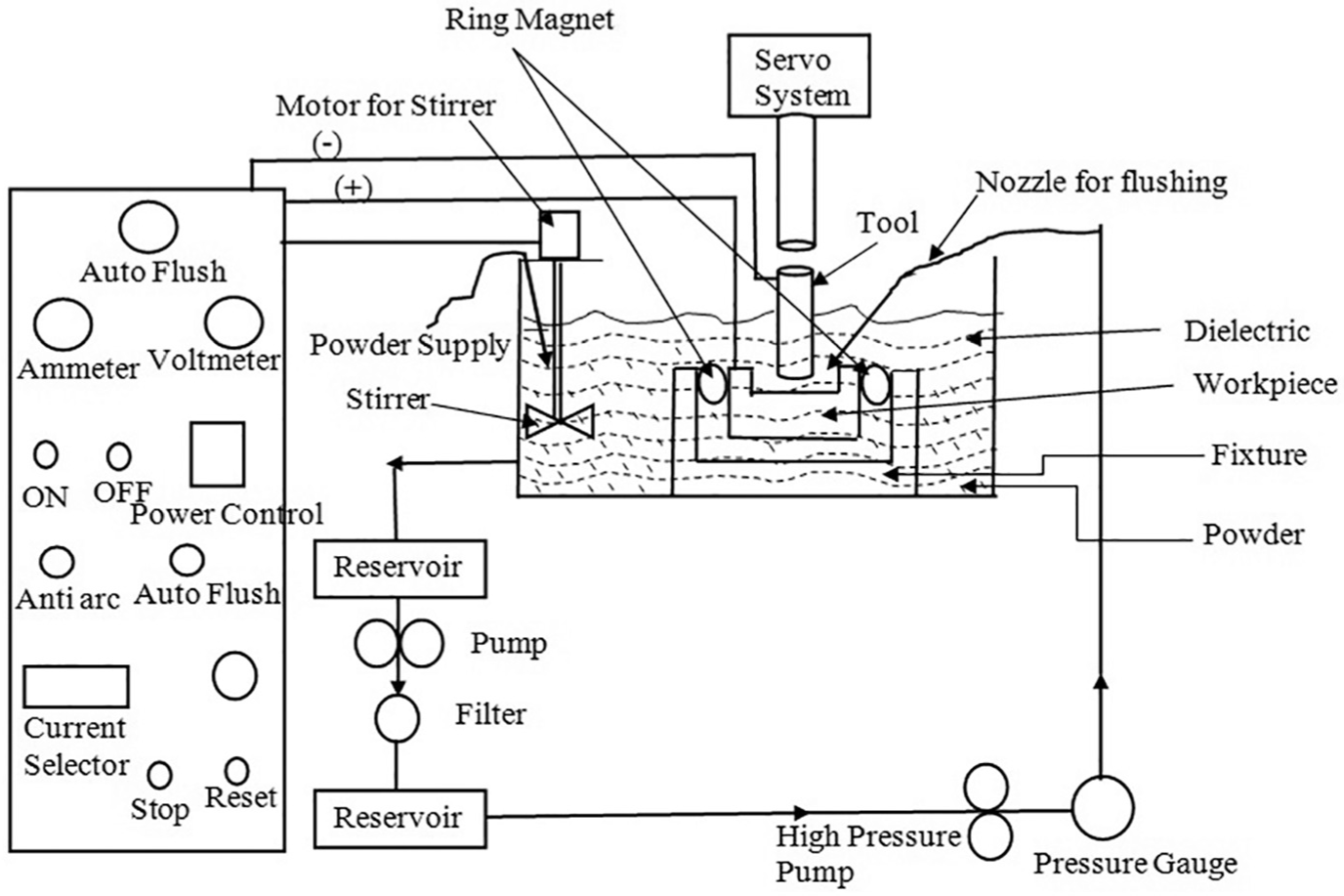
Schematic diagram of MFAPMEDM setup.
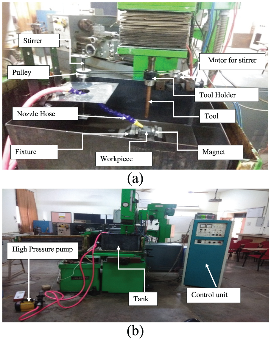
Fabricated model of MFAPMEDM setup: (a) fabricated tank along with attachments and (b) attachments with EDM setup.
Working principle
Mechanism of MFAPMEDM is divided into five parts as shown in Figure 4(a)–(e). Figure 5(a) and (b) depicts the discharge phenomenon in the machining gap and the different phases of discharge between tool and workpiece under the influence of powder as well as MF.
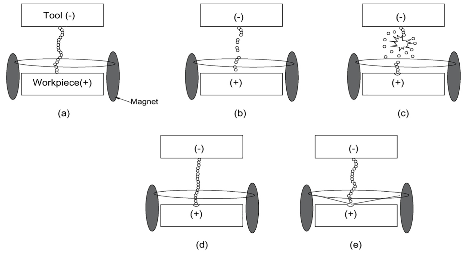
MFAPMEDM material removal mechanism: (a) bridge formation, (b) spark initiation due to breakage of powder chain, (c) explosion leading to zigzag particle motion, (d) re-bridging and (e) shifting of debris particles under the influence of Lorentz force.
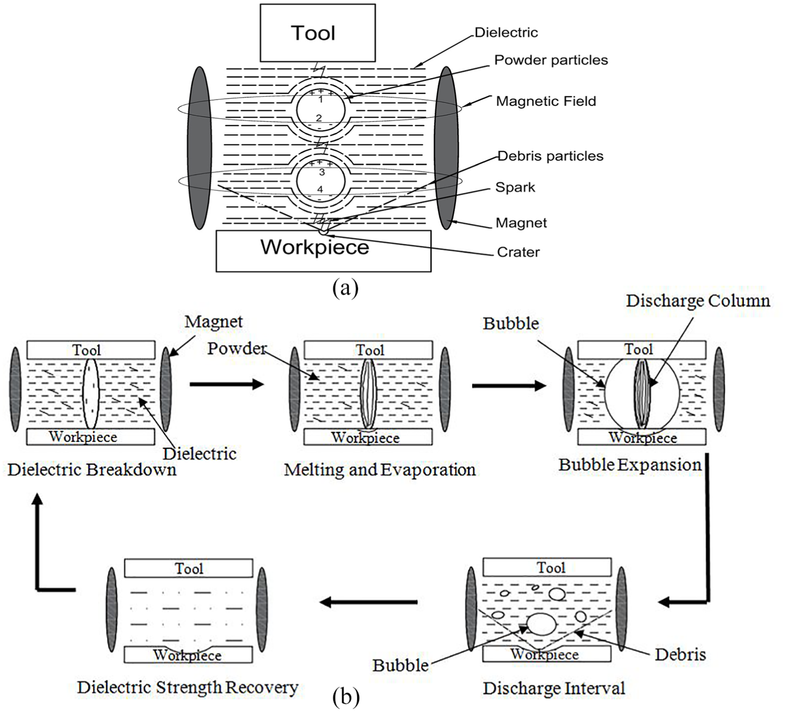
Schematic view of material removal action in the machining gap: (a) discharge phenomenon in machining gap and (b) different phases of discharges.
During this process, when a voltage of 80–320 V is applied across the tool electrode and the workpiece immersed in dielectric media, an electrical intensity in the range of 105 to 107 V/m is produced. Also, positive and negative charges are formed at the top and bottom of the powder particles, as shown in Figure 5(a). Conductive powder under the influence of this generated electric intensity gets energized behaving in a zigzag fashion. In Figure 5(a), at points 1 and 2 on adjacent powder particles, highest electrical intensity was observed which reduces the breakdown strength of dielectric. The short circuit occurs between two powder particles due to electrical discharge and redistribution of electrical charges takes place. Then, at points 3 and 4, accumulation of electric charges takes place creating the discharge between these two powder particles causing series of discharges. However, when these powder particles come under the sparking area between the tool and the workpiece, they arrange themselves in the form of chain-like structure at different places. The chain formation helps in bridging the gap between tool electrode and workpiece, as a result of which the insulating strength of dielectric is reduced causing an early explosion in the gap. Due to the early explosion, series discharge takes place under the sparking area enhancing the increase in discharge frequency leading to faster erosion from the surface of a workpiece. As a result of which, gap contamination facilitates ignition process and increases gap size thereby improving process stability. Added powder to dielectric media removes the material due to combined effect of mechanical thrust driven by gas bubbles explosion caused mainly from the working fluid evaporation and striking impact of suspended particle as shown in Figure 5(b). This facilitates the enlargement and widening the plasma channel as a result of which electrical intensity decreases. Due to this, sparks are uniformly dispersed among the powder particles causing shallow craters on the workpiece material. However, at the same time, electric force (FE) and magnetic force (FM) are developed due to electric field and MF generates resultant force (FL) called as Lorentz force as stated in Figure 1. This Lorentz force accounts for increasing the electron density and changes the path of electrolytic ions by reducing the mean free path shifting of debris from the workpiece and tool in the discharge zone. Thus, this Lorentz force has significant impact on the plasma channel which effectively expelling the debris particles leading to increase erosion volume and maintaining uniform discharge waves by gap causing improvement in MRR and surface finish.8,16,19
Materials and methods
Experimental material
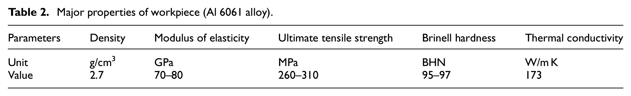
Al 6061 alloy of dimension 40 mm × 40 mm × 10 mm as a workpiece material and a copper rod of diameter 12 mm as a tool electrode were selected for conducting the experiments in the present study. The experiments were performed using aluminum powder mesh size 200 mixed with EDM oil as dielectric fluid along with the neodymium ring magnet placed on the side of workpiece. The chemical composition (wt%) of Al 6061 alloy is given as Al (97.87), Mg (0.8), Si (0.4), Fe-(max. 0.70), Cu (0.15), Ti-(max. 0.15), Mn-(max. 0.15), Cr (0.04). The major properties of workpiece material are depicted in Table 2.
Major properties of workpiece (Al 6061 alloy).
Experimental equipments
A die-sinking electrical discharge machine with fabricated components attached Make Elektra model-EMS 5030 equipped with ELECTRONIA PRS-20 controller having maximum discharge current of 35 A and power factor of 0.8 as depicted in Figure 3(a) and (b) is used in this experimental study.
Experimental design
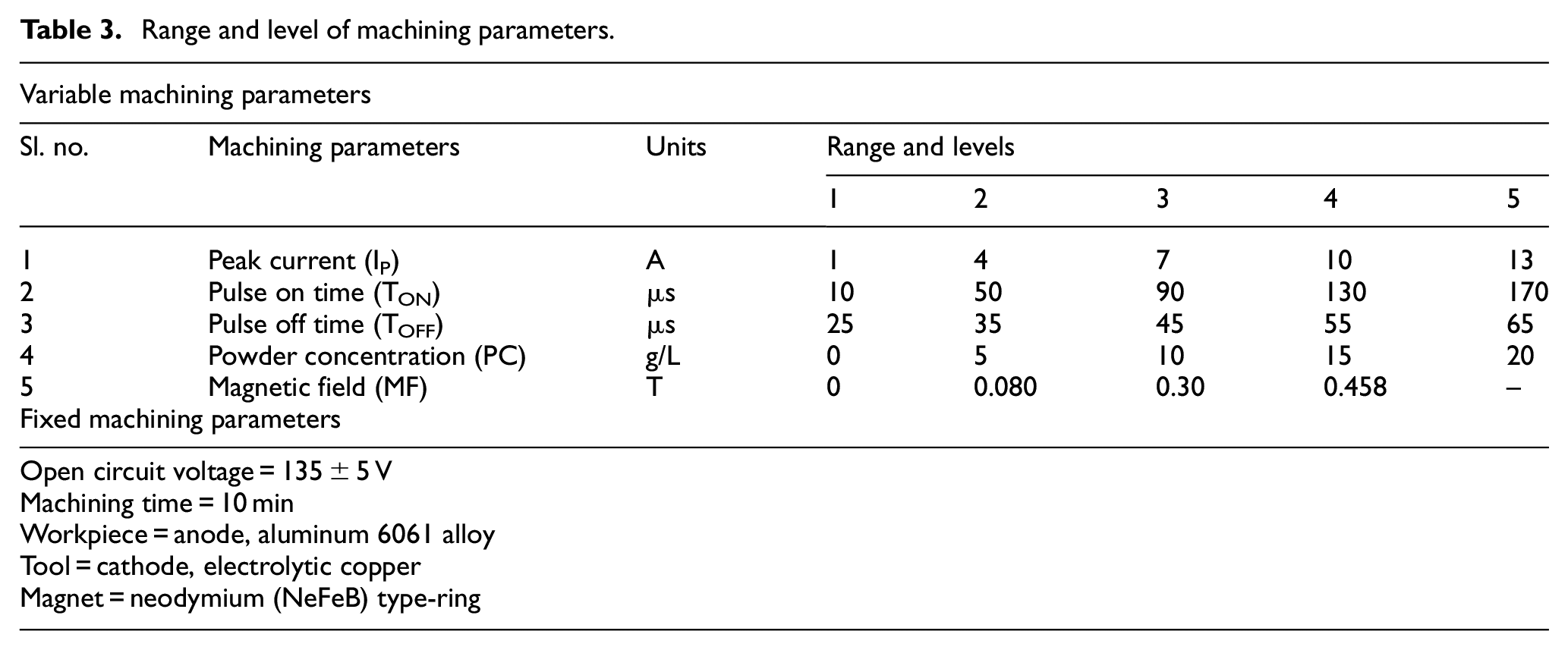
Five process parameters are considered for this experimental work with five level for peak current, pulse on time, pulse off time and PC, while four level for MF based on machine setup range and literature review of various researchers. For this experimental work, one factor at a time (OFAT) design approach is considered. The range and level of machining parameters are shown in Table 3.
Range and level of machining parameters.
Performance characteristics
For this experimental work, TWR and MRR are considered as performance characteristics. For TWR and MRR, weight before and after machining is measured with the help of digital weighing balance model SI-215D make Denver Instruments with capacity of 210 g and resolution of 0.1 mg. The TWR and MRR are calculated using equation (1)
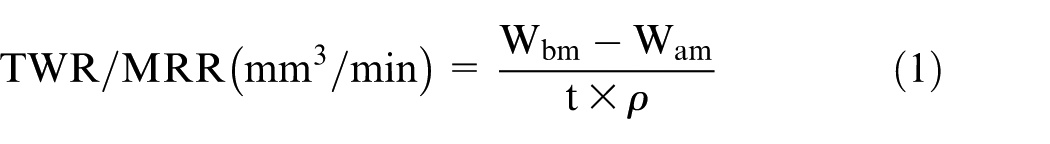
where Wbm is the tool or workpiece weight before machining (g), Wam is the tool or workpiece weight after machining (g), ρ is the density of tool or workpiece (g/cc) and t is the time of machining (min).
Results and discussion
Experimental design according to OFAT for different machining parameters along with the results is displayed in Table 4.
OFAT design with experimental results.
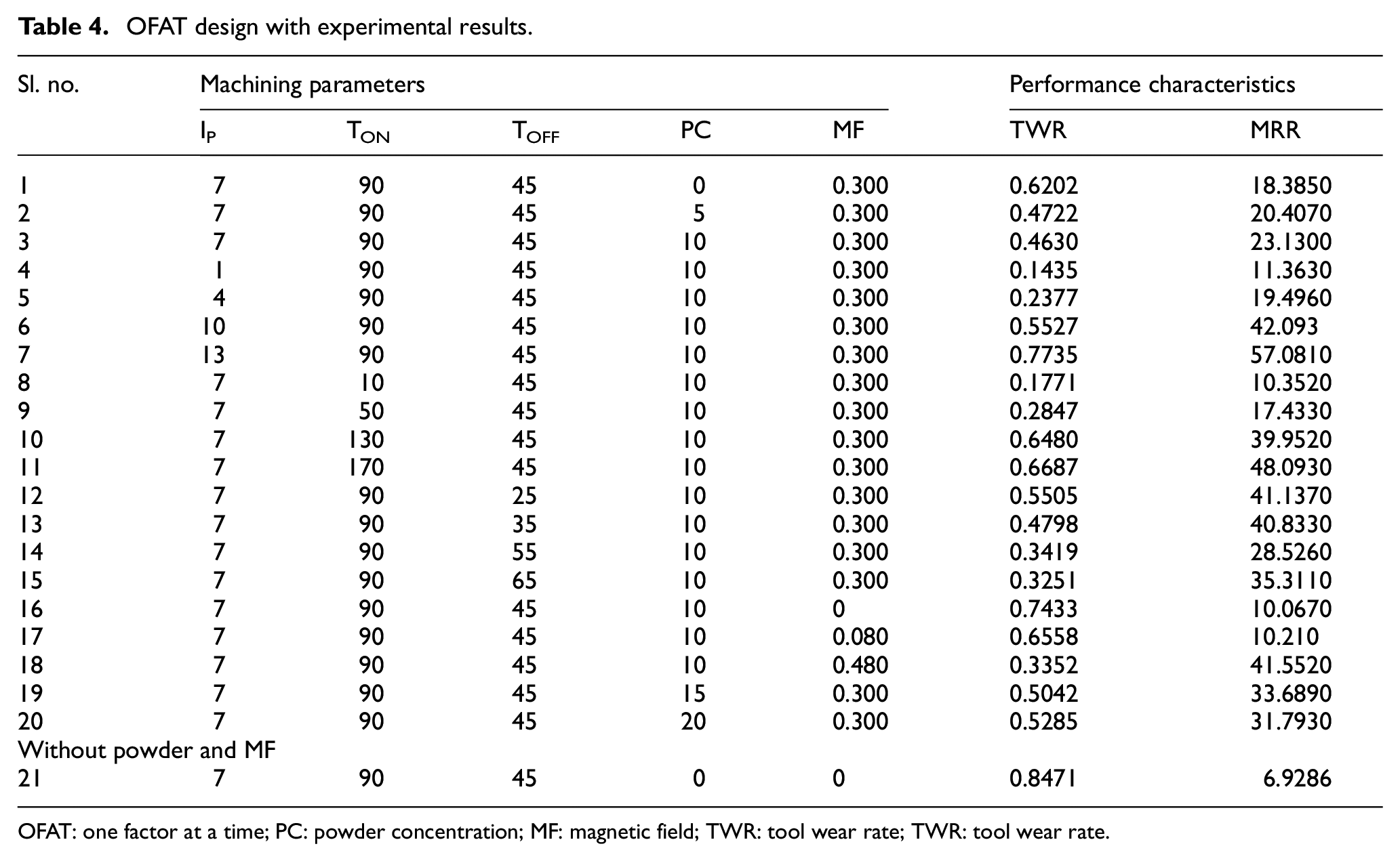
OFAT: one factor at a time; PC: powder concentration; MF: magnetic field; TWR: tool wear rate; TWR: tool wear rate.
Effect of peak current on MRR and TWR
The effect of peak current on MRR and TWR is illustrated in Figure 6. It can be observed from Figure 6, while increasing the peak current from 1 to 13 A, increase in MRR was observed from 11.3630 to 57.0810 mm3/min. This is mainly due to increase in spark as a result of an increase in current intensity, thus increasing the melting and vaporization during machining from the surface of the workpiece.5,13 However, for the same increment in IP, TWR was observed to increase from 0.1435 to 0.7735 mm3/min. The increase was as a result of increment in electrical power causing the high melting from the tool electrode due to spark energy proportional to peak current at constant TON.
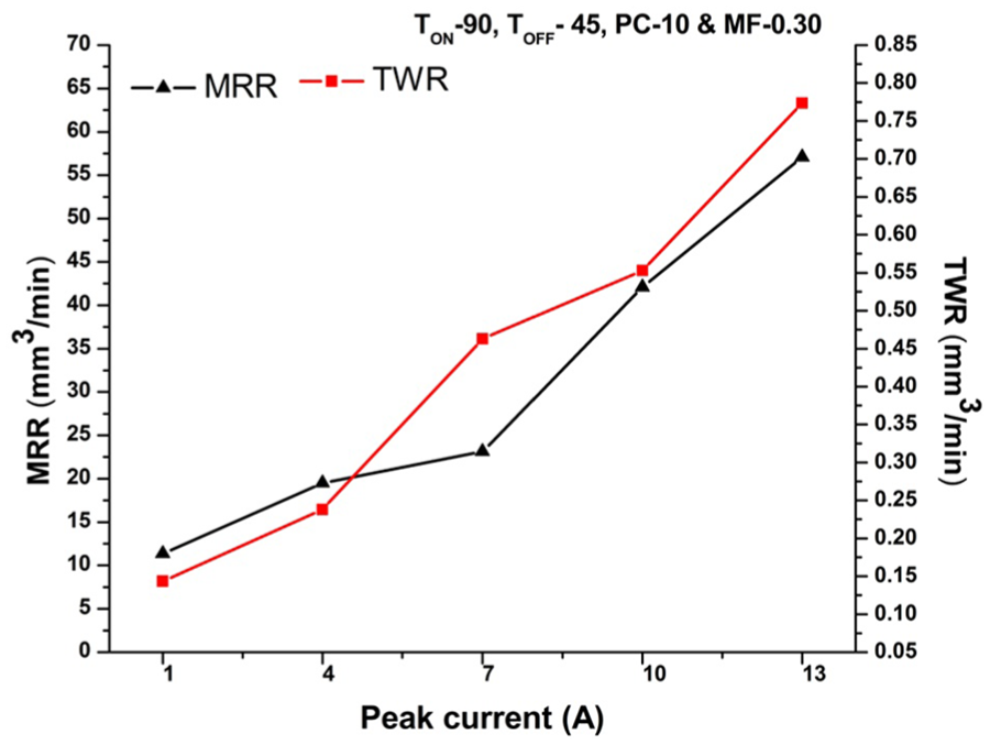
Effect of peak current on MRR and TWR.
Effect of pulse on time on MRR and TWR
Figure 7 shows the effect of pulse on time on MRR and TWR. It was observed that with increase in pulse on time from 10 to 170 µs, MRR was increased from 10.3520 to 48.0930 mm3/min while TWR was increased from 0.1771 to 0.6682 mm3/min. The reason for the increase in MRR and TWR was due to higher spark energy generated which melts and evaporates the materials for a longer period with an increase in TON causing the larger crater on the machined workpiece and tool material. However, increase in MRR and TWR is also attributed to the spark energy which is directly proportional to the TON at constant Ip.5,12
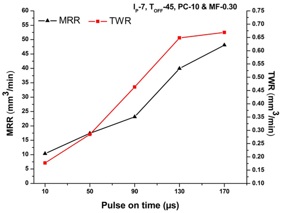
Effect of pulse on time on MRR and TWR.
Effect of pulse off time on MRR and TWR
The effect of pulse off time on MRR and TWR is displayed in Figure 8. It was observed from Figure 8 that MRR decreases from 41.1370 to 23.1300 mm3/min on increasing TOFF from 25 to 45 µs while on further increasing TOFF from 45 to 65 µs increment in MRR from 23.1300 to 35.3110 mm3/min was observed. The increase in MRR up to certain value was because of arcing which a result of improper is flushing due to low TOFF. However, a further increase in MRR with an increase in TOFF was due to proper flushing as a result of higher TOFF. From Figure 8, it can be seen that TWR decreases from 0.5505 to 0.3251 mm3/min on increasing TOFF from 25 to 65 µs; this could be due to spark which gets less time to be in contact with the workpiece material resulting in the decrease in TWR.5,12
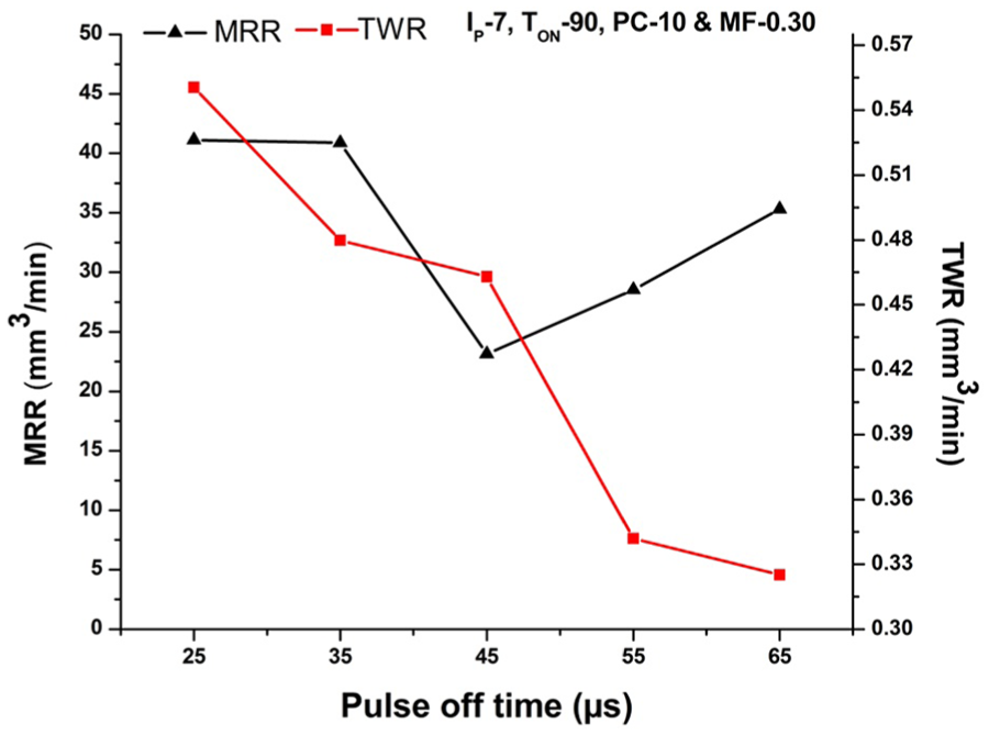
Effect of pulse off time on MRR and TWR.
Effect of PC on MRR and TWR
Figure 9 describes the effect of PC on MRR and TWR. From Figure 9, it was observed that with an increase in PC from 0 to 15 g/L in EDM oil, MRR increases from 18.3850 to 33.6890 mm 3 /min. This is attributed to the phenomenon that increases in PC lower the strength of dielectric fluid. Further bridging of powder particles occurs resulting in multiple discharges increasing the frequency of the spark resulting in higher MRR. On further increasing PC from 15 to 20 g/L, the MRR gets reduced to 31.7930 mm3/min. This is mainly due to collection of powder particles getting accumulated under the sparking area causing uneven discharge making process unstable by reducing the MRR.5,12 Low TWR was observed on machining the Al 6061 alloy with fine powder mixed with EDM oil in the presence of the MF as depicted from Figure 9. TWR decreases from 0.6202 to 0.4630 mm3/min with increase in PC from the 0 to 10 g/L; this was mainly due to narrow channel obtained as a result of powder addition which transfers the heat to the workpiece causing reduction in TWR. However, on increasing the PC from 10 to 20 g/L, increase in TWR from 0.4630 to 0.5285 mm3/min was noticed. This was mainly due to the result of high PC causing increment in discharge frequency leading to increase in TWR.5,11,12
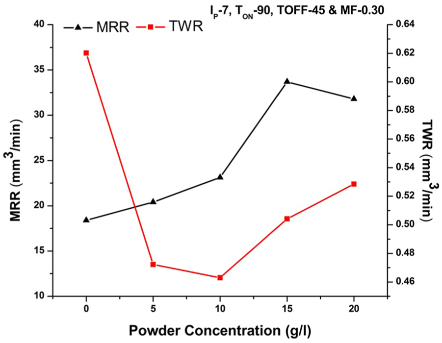
Effect of powder concentration on MRR and TWR.
Effect of MF on MRR and TWR
The effect of MF on MRR and TWR is illustrated in Figure 10. It was observed that the effect of MF on TWR is decreasing from 0.7433 to 0.3352 mm 3 /min, whereas MRR is increasing from 10.0670 to 41.5520 mm 3 /min with the increase in MF from 0 to 0.480 T. The reason for the reduction in TWR is because as copper is diamagnetic in nature and when opposing MF is induced, it repels the removed material away from the tool causing low TWR at higher MF. The increasing trend of MRR is observed due to confinement of plasma causing the increment in depth and reduction in crater size as well as expelling the machining debris from the machining area effectively clearing the gap under sparking area due to Lorentz force developed due to MF along with electric field.5,14,15
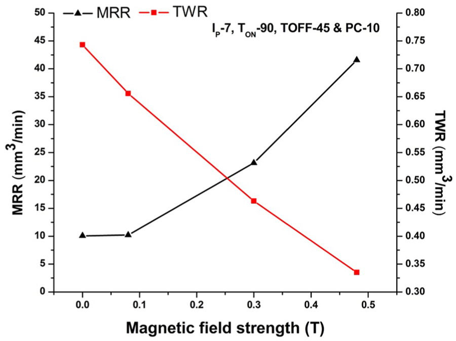
Effect of magnetic field on MRR and TWR.
Conclusion
In this present work, MF assisted powder mixed EDM setup is fabricated and was used successful in carrying out the machining of Al 6061 alloy. OFAT approach is considered to study the effect of machining parameters namely peak current, pulse on time, pulse off time, PC, and MF on performance characteristics MRR and TWR. The following findings were obtained from the present experimental work:
TWR was increased with increase in peak current and pulse on time, decrease in pulse off time and MF, while with increase in PC, TWR was decreasing up to certain value and then increases.
MRR was increased with increase in peak current, pulse on time and MF, decrease in pulse off time, while with increase in PC, MRR increases up to certain value and then decreases.
Highest MRR (57.080 mm3/min) was obtained with 13 A IP, 90 µs TON, 45 µs TOFF, 10 g/L aluminum PC and 0.3 T MF, whereas low TWR was observed at 1 A IP, 90 µs TON, 45 µs TOFF, 10 g/L aluminum PC, and 0.3 T MF.
Footnotes
Declaration of conflicting interests
The author(s) declared no potential conflicts of interest with respect to the research, authorship and/or publication of this article.
Funding
The author(s) received no financial support for the research, authorship and/or publication of this article.