
Abstract
Accomplishment of high machining rates along with good surface quality is a major concern in electric discharge machining process. Powder-mixed electric discharge machining in which suitable powder particles are impregnated in dielectric has gone forth as a potential solution to this problem. Nevertheless, challenges such as dielectric circulation, homogeneous blending of the powder particles in the dielectric, debris removal and quantity of the powder material required have to be addressed carefully before implementing this process on a large scale in the manufacturing industry. Extensive research in the field of electric discharge machining using powder-suspended dielectrics has started only in the recent years. In this article, a comprehensive review of the research going on in the field of powder-mixed electric discharge machining is presented. The emphasis is given on powder-mixed electric discharge machining mechanism, influence of powder characteristics and machining parameters on various responses. Some of the major application areas, variants of the basic powder-mixed electric discharge machining process and possibilities of further improvement are also discussed.
Keywords
Introduction
Notwithstanding the capability to machine virtually any electrically conductive material, the applications of electric discharge machining (EDM) are restricted to a few industries, due to poor productivity and surface quality of the machined components. Over the years, researchers have developed new variants to EDM for enhancing its performance. Some of them include the insulation of electrodes using high resistance coatings, usage of multiple electrodes, rotation and ultrasonic vibration of the electrode and utilization of powder-mixed dielectric.
The invention of powder-mixed electric discharge machining (PMEDM) process took place around late 1970s and the first publication came in 1980. 1 In PMEDM, the addition of suitable powder particles to the dielectric leads to a superior surface finish and better machining rate compared to those for conventional EDM (without powder-mixed dielectric). A novel EDM two-tank system was first developed and marketed by Mitsubishi. 2 One of the tanks consisted of standard dielectric oil and the second one contained powder-mixed dielectric. After completion of initial machining operation in the first tank, the tool head moved to the second tank to perform the finish machining. However, the extensive application of PMEDM in the industry requires a thorough understanding of its mechanism and the influence of different powder characteristics on performance measures.
This work presents a comprehensive and critical review of the research carried out in the area of PMEDM. The emphasis is given on PMEDM mechanism, influence of powder characteristics and machining parameters on various responses including surface integrity. Some of the major application areas, variants of the basic PMEDM process and potential future direction of research are also discussed.
Mechanism of PMEDM
A typical dielectric circulation system used in PMEDM is shown in Figure 1. This kind of a specially designed system is mounted in the working tank of an EDM setup. A stirrer or a micro-pump is provided to avoid the settling of powder particles at the bottom of the dielectric reservoir. It also helps to prevent the stagnation of the powder particles on the workpiece surface. A set of permanent magnets are provided to separate the debris from the powder particles. However, such technique would be successful only when the workpiece is magnetic in nature and the powder material is not.
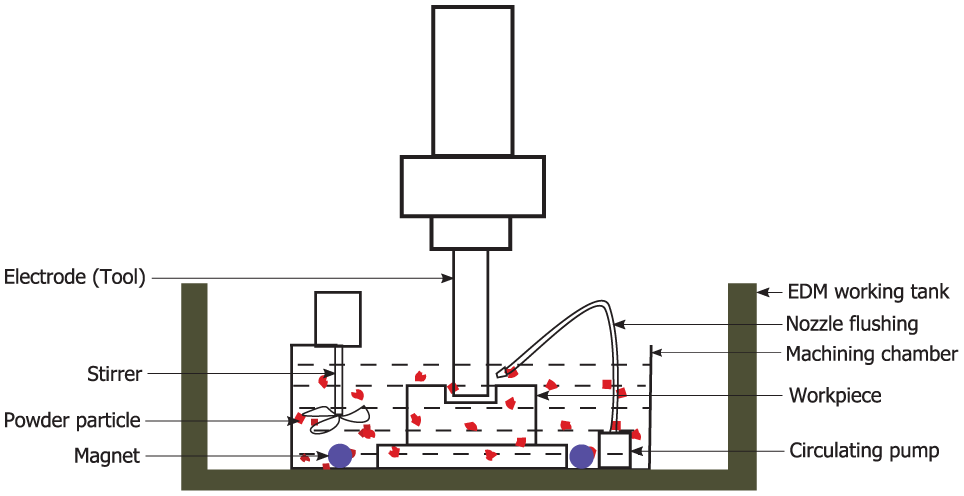
Typical PMEDM setup.
Mechanism of PMEDM according to the current understanding is discussed below as the process is yet to be fully established. In PMEDM, fine powder particles are suspended in the dielectric oil. An electric field is created in the inter-electrode gap (IEG) when sufficient voltage (about 80–320 V) is applied between the tool and workpiece. Ionization of dielectric takes place as in case of conventional EDM. Under the applied electric field, positive and negative charges accumulate at the surfaces of the powder particles adjacent to cathode and anode, respectively, as shown in Figure 2. The capacitive effect of the electrodes leads to the formation of chains of powder particles. First discharge breakdown occurs where the electric field density is the highest (between “a” and “b” in Figure 2). This breakdown may be between two powder particles or a powder particle and an electrode (tool or workpiece). Redistribution of electric charges takes place after the first spark and electric charges gather at points “c” and “d.” Thus, the process continues through series discharges.3,4
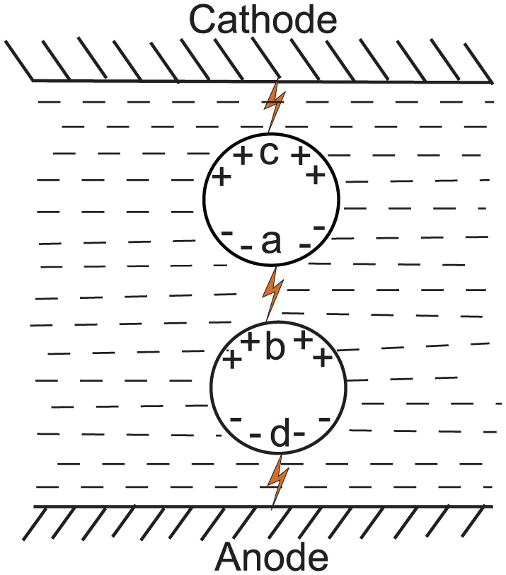
Series discharging in PMEDM. 3
Enlargement of the discharge gap
The size of a discharge gap largely depends on the electrical and physical properties of the powder particles. Under the condition of high temperature, the free electrons in electrically conductive powder particles reduce the overall resistance of the dielectric. The improved conductivity helps the spark to be generated from longer distance and thus enlarges the discharge gap.5,6
Widening of the discharge passage
After the first discharge, powder particles in IEG get energized and move rapidly along with ions and electrons. These energized particles collide with dielectric molecules and generate more ions and electrons. Thus, more electric charges are produced in PMEDM compared to conventional EDM. Increased discharge gap also aids in the reduction in hydrostatic pressure acting on the plasma channel. The combined influence of these two phenomena ensures the widening of the discharge passage. The enlarged and widened discharge column decreases the intensity of discharge energy, leading to the formation of large shallow cavities on the workpiece surface. 3
Multiple discharges
Multiple discharge paths are observed in PMEDM due to the rapid zigzag movement of the suspended powder particles which maintain a uniform distribution of energy and formation of multiple craters by single discharge. A typical voltage waveform in a PMEDM operation is shown in Figure 3. Unlike conventional EDM, the discharge waveform in the case of PMEDM is significantly different from the input pulse. Evidently, there is more perturbation in voltage and current signals during a pulse-on time indicating multiple discharges.7,8
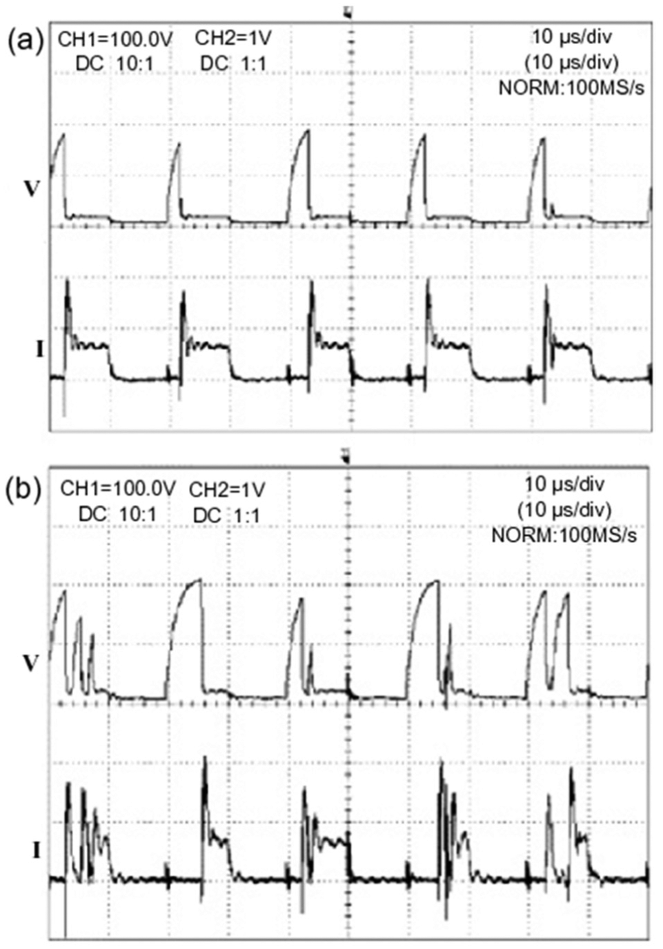
Voltage and current waveforms in (a) EDM and (b) PMEDM. 7
Influence of powder properties on machining characteristics
Selection of powder material in PMEDM plays a pivotal role in influencing various performance measures of the process. Therefore, evaluation of powder properties and their possible correlation with EDM characteristics are of utmost significance. Jahan et al. 9 presented a comprehensive analytical modeling of PMEDM process. Figure 4 shows the schematic representation of different forces acting on a powder particle in the IEG. In Figure 4, Fl, Fc, Fd, Fe and “f” are lift, columbic, drag, electric and friction (direction only) forces, respectively. W denotes the self-weight of the particle.
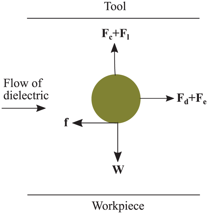
Different forces acting on a powder particle.
The derived formula for breakdown energy of powder-mixed dialectic is provided in equation (1)
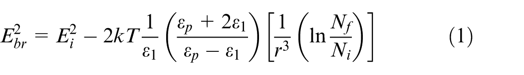
where
From equation (1), it is evident that
The derived expression for spark gap during PMEDM is given in equation (2)

where
Density, size, electrical and thermal conductivities are some of the critical characteristics of the powder particles that affect PMEDM process.
An increase in electrical conductivity of the dielectric and the resulting extension of discharge gap in PMEDM, as discussed earlier, enhance spark frequency and facilitate removal of debris from the machining zone.9,10
High thermal conductivity of powder particles removes a large amount of heat from the discharge gap leading to reduction in discharge density. Therefore, only shallow craters are formed on the workpiece surface.11,12 The number of surface cracks developed on the machined surface is also reduced along with their width and depth, as the intensity of discharge energy is less in PMEDM compared to conventional EDM process.13,14
The number of powder particles in the electrode gap at a given instant increases with the decrease in their size. As a consequence, the overall discharge energy increases, but it is more evenly distributed in a larger area. Hence, energy density gets diminished. 9 Formation of multiple numbers of smaller craters during a single discharge also takes place. Use of smaller powder particles has, therefore, produced higher material removal rate (MRR) and superior surface quality compared to the larger size particles of the same material.15–18
The powder particles with low density can balance themselves better against the surface forces, allowing even distribution of particles throughout the dielectric.19,20 Low density also minimizes the amount of powder particles settling at the bottom of the tank, thereby bringing down the requirement of powder quantity. Lighter particles also cause small explosive impact on the molten metal. 11 Some of the frequently used powder materials in PMEDM along with their properties are presented in Table 1.
Properties of powder materials. 21
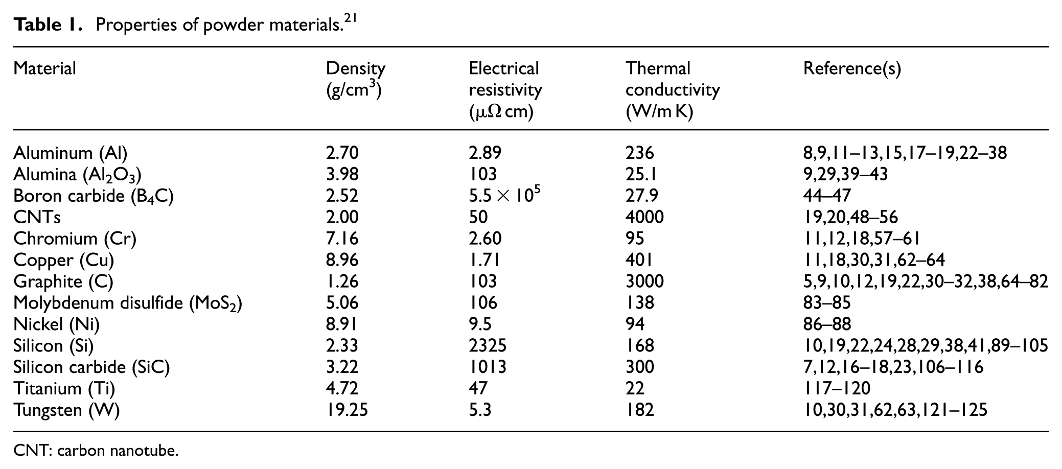
CNT: carbon nanotube.
Yeo et al. 108 observed a circular growth within the crater during powder-mixed micro-EDM (µ-EDM) process due to the deposition of the powder material on the workpiece surface. However, no such growth could be found during conventional EDM process.
Along with the physical, electrical and thermal properties, concentration of powder material in the dielectric also causes a significant change in the responses. 38 Higher concentration is effective in multiplying the number of discharges which, in turn, augment MRR.101,102 The accentuation of multi-sparking in a single pulse-on time due to increase in powder concentration reduces the energy per spark resulting in low surface roughness (SR). 23 However, too many powder particles in the discharge gap hinder the discharge energy transfer to the workpiece. It also leads to arcing and short-circuiting that ultimately results in low MRR and poor surface quality.85,104
On the contrary, Jabbaripour et al. 12 observed a fall in MRR, when powders such as Al, graphite, SiC, Cr and Fe had been impregnated in the dielectric during the PMEDM of ϒ-TiAl intermetallic. Such reduction was attributed to the reduced energy density at the discharge spot due to enlarged IEG and widened discharge passage. Consequently, the reduced impulsive force of the plasma channel on the workpiece surface also resulted in the formation of small craters leading to the reduction in MRR.
Figure 5 also indicates that powders such as Fe and Cr that have low thermal conductivity and high density produced superior MRR. According to the authors, powders that have high thermal conductivity take away the heat from the discharge spot resulting in lower values of MRR. Low-density particles produced poor MRR as they mixed well with the dielectric and dissipated more heat to the dielectric. Hence, Al with highest thermal conductivity and the least density among the used powders produced the worst MRR.
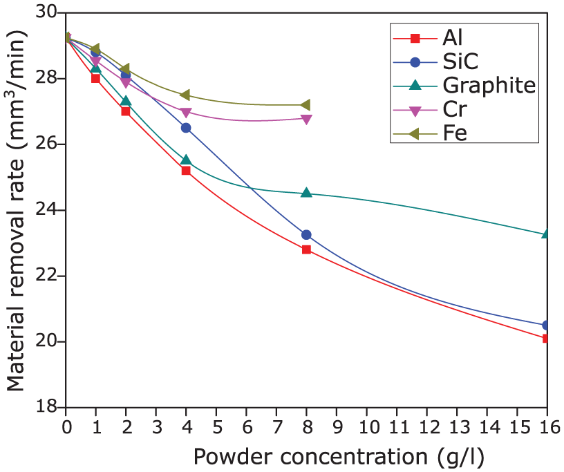
Effect of different powders on MRR during PMEDM. 12
Wu et al. 25 achieved excellent surface finish by mixing a surfactant (polyoxyethylene-20-sorbitan monooleate) along with Al powder in dielectric during the EDM of SKD 61 die steel. The added surfactant acted as a steric barrier to prevent the agglomeration of the powder particles. It was also found that usage of only surfactant as an additive could reduce the recast layer thickness (shown in Figure 6) as it increased the overall conductivity of the dielectric. 126
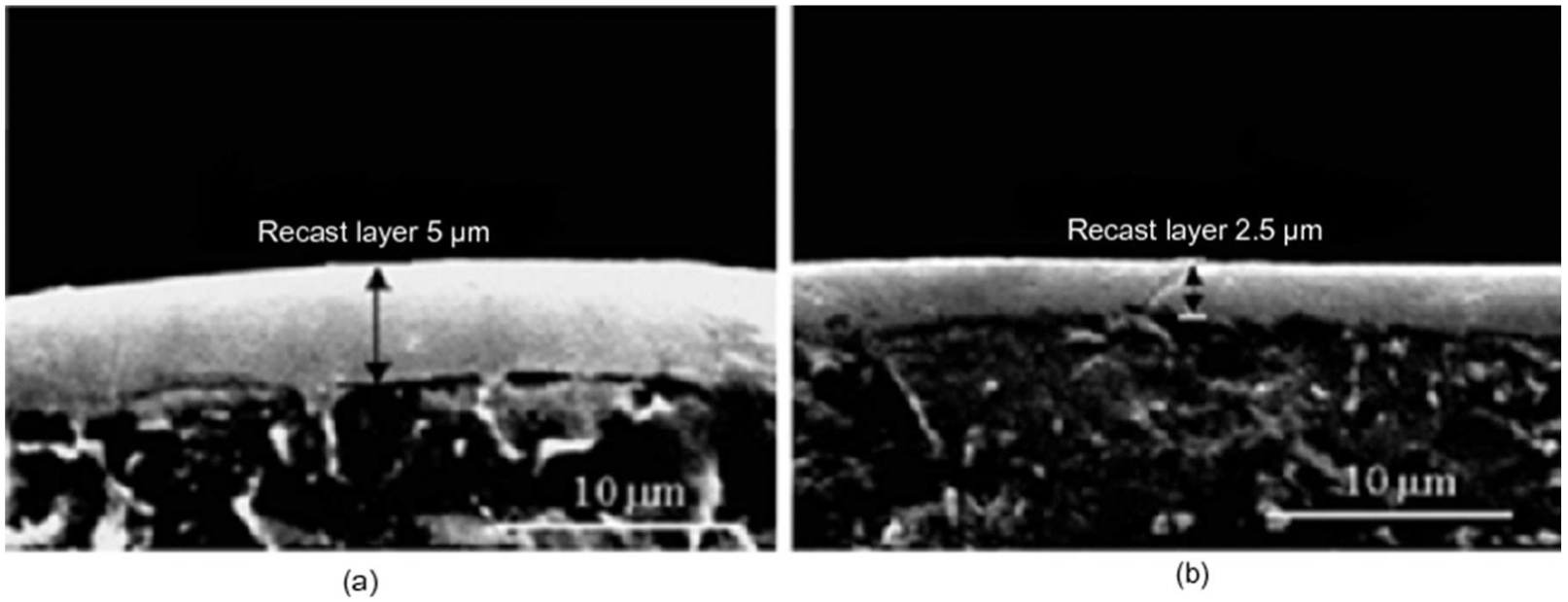
SEM micrographs of recast layer using (a) kerosene and (b) kerosene + span20 as dielectrics. 126
Radial pattern and a trace of the circular annulus at the edge of the machined surface were found by Wang and colleagues,99,100 at 4 g/L concentration of Si powder in the dielectric while machining NAK-80 mold steel. All the negatively charged electrons collide with the positive charges present on the workpiece surface generating enormous amount of heat energy. A track with branches radially growing outward was formed due to rapid heat transfer to surroundings. The track disappeared at higher levels of powder concentration as powder congregation died down.
In addition to conventional metallic powders, potential of few different types of powder has also been evaluated in recent times. Among others, Tsai and colleagues29,39,41 established the feasibility of polymer particles (starch, polyaniline) as additives during the PMEDM of stainless steel. Starch when added along with Al2O3 powder in silicone oil produced better surface quality than pure Al2O3 powder. Wong et al. 22 utilized crushed glass as an additive to machine AISI-01, SKH 54 tool steels and found no significant effect of it on both MRR and surface quality due to its very poor electrical and thermal conductivities. Sari et al. 20 and Prabhu and colleagues48–51,53–56 concluded that carbon nanotubes (CNTs) mixed in the dielectric resulted in huge improvement of MRR compared to other powder materials. This phenomenon was attributed to the low density and high thermal conductivity of CNT. The low density allowed the particles to be better balanced against the surface forces of the dielectric. Hence, there was an even distribution of the particles in the dielectric. High thermal conductivity also helped in the uniform distribution of discharge energy over the large surface area. Mai et al. 19 used CNTs fabricated using floated catalytic chemical vapor deposition (CVD) method during the PMEDM of NAK-80 steel. The uniform diameter and straight pin shape of these CNTs allowed easier separation from each other compared to CNTs produced using conventional CVD technique. As high as 66% increase in MRR and 70% decrease in SR were reported with 0.4 g/L concentration of CNTs.
Influence of machining parameters on characteristics of PMEDM
The combined and individual characteristics of dielectric, powder, tool and workpiece material along with other machining parameters affect the PMEDM process significantly.30–32 The effect of important process parameters on the machining characteristics of PMEDM process is discussed below.
Dielectric
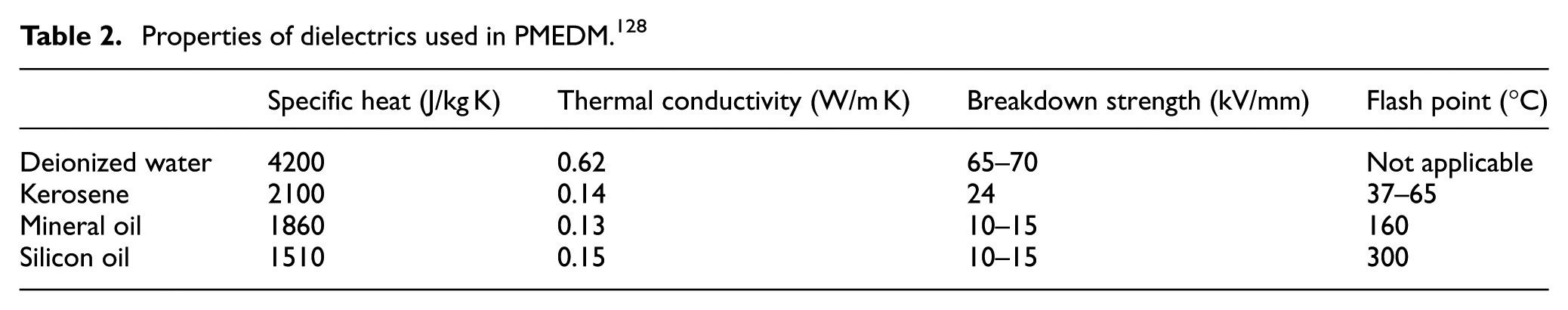
Apart from commercial EDM oils, kerosene and deionized water are widely used in PMEDM. The higher thermal conductivity and specific heat of pure water take away the heat from the machining zone resulting in a better cooling effect. 106 Simultaneously, kerosene forms carbides and water forms oxides on the machined surface. Carbides require more thermal energy to melt compared to oxides. 44 Hence, higher MRR and less tool wear rate (TWR) were realized with deionized water than kerosene as dielectric. But kerosene produces better surface finish. Usage of emulsified water (water + emulsifier + machine oil) as the dielectric by Liu et al. 127 produced higher MRR and better surface quality than pure kerosene. This was attributed to the increase in overall electrical conductivity of the dielectric due to the ionization of water-soluble anionic compound emulsifier present in the emulsified oil. Some of the important properties of dielectrics used in PMEDM are provided in Table 2.
Properties of dielectrics used in PMEDM. 128
Polarity
Discharge current takes place due to flow of both electrons and ions. For short pulse-on time, the discharge current is mainly due to the electron current. When the pulse-on time is long, the discharge consists of a large amount of ion current. Hence, for better MRR and lower TWR, positive polarity (workpiece +ve) with short pulse-on time should be preferred while negative polarity (workpiece −ve) can be used for long pulse-on time. 7
Figure 7 shows scanning electron microscope (SEM) images of the craters formed during the EDM of a titanium alloy using SiC additive in the dielectric. 107 With positive polarity, some of the molten metal solidified at the center of crater resulting in bulging effect. It also led to a greater accretion of powder material on the machined surface. 117 Furthermore, deep cavities with predominant ridges were observed with negative polarity. This means that high MRR could be achievable with negative polarity but with coarser surface.99,129
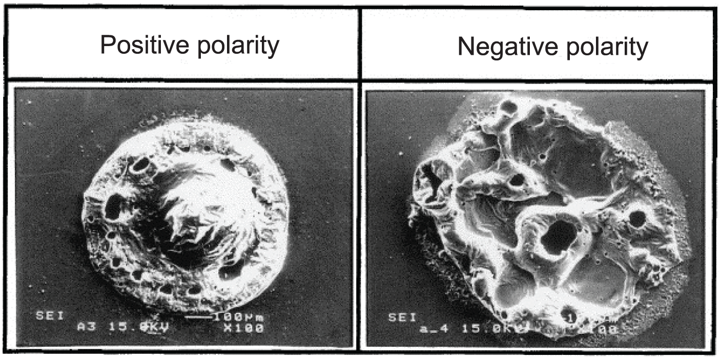
Influence of polarity in PMEDM. 107
Peak current
MRR increases with peak current due to an increase in discharge energy.130–134 The increase in peak current also increases the number of electrons and ions per unit volume, thereby increasing the pressure in the plasma channel. As a consequence, impulsive force per unit area (specific impulsive force) increases allowing an easier ejection of the molten material.103,104 Tool wear increases with increasing pulse current as more particles strike the surface. However, pulse energy dominates striking effect at high pulse current leading to less tool wear.15,87
Surface quality deteriorates with peak current as the quantity of material removed per discharge increases due to rise in discharge energy. 135 Large and deep craters were observed at high pulse currents. 25 The thickness of recast layer also increases as more material melts and re-solidifies. 122 Apart from material transfer, rapid heating and quenching at high pulse currents elevate the microhardness of the machined surface. 136
Figure 8 shows images obtained using transmission electron microscopy (TEM) clearly indicating metallurgical changes in the recast layer during machining of Ti with Ti-suspended dielectric with a concentration of 3 g/L and pulse-on time of 30 µs. Columnar grains with a cubic structure shown in Figure 8(a) were confirmed to be consisting of TiO phase. The same TiO phase was also observed in Figure 8(b). However, no rutile (TiO2) was observed because of the quick dissipation of heat to the surroundings at low peak current and short pulse-on time.
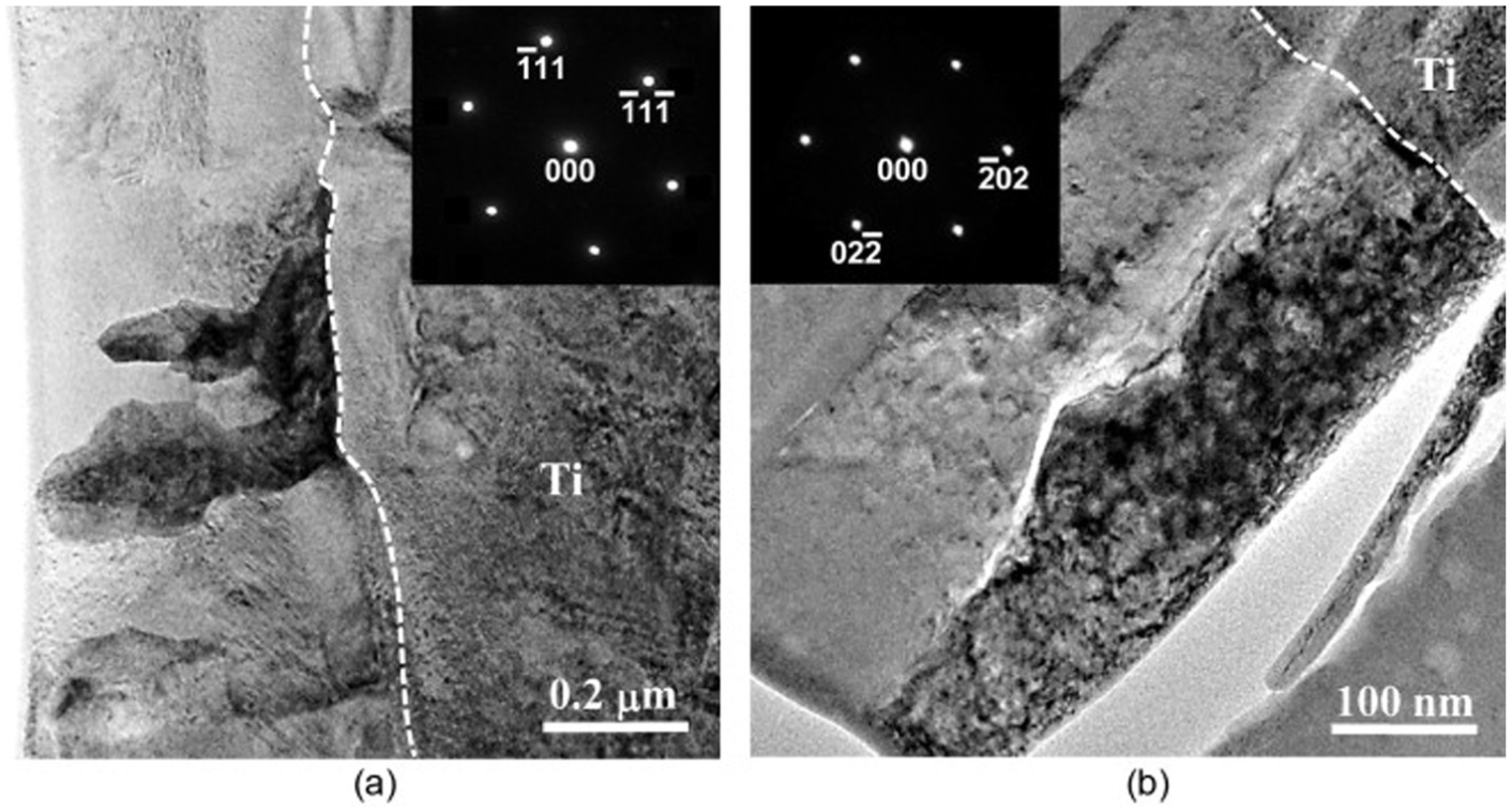
TEM images of the cross section from foil normal: (a) [110] at 0.1 A and (b) [111] at 0.3 A. 120
Pulse-on time
MRR increases with pulse time due to an increase in pulse energy.15,43,103 Too long pulse-on time causes an expansion of the plasma channel that, in turn, leads to the reduction in energy density and impact force. Thus, MRR is reduced at long pulse-on time. 126 SR also decreases with pulse-on time due to aforesaid reasons. Short-circuiting and incomplete removal of debris from the discharge area make the process unstable and degrade the surface quality at high pulse times.25,78,96 More debris is formed and adheres to the machined surface as the pulse time increases the productive machining time. This also causes an increase in recast layer thickness.44,112 There is an initial decrease in microhardness of the machined surface, followed by subsequent rise with further increase in pulse-on time due to material transfer. 136 TWR decreases with the pulse time due to the time available for heat transfer from the molten crater to the body of the electrode. High wear resistance of the electrode due to the deposited carbon on it increases the TWR. 67 More overcut (OC) was observed with high pulse-on time owing to the large amount of material removed per spark. 129
Yasar and Ekmekci 114 observed many small pits within the crater with a decrease in pulse time. At high pulse times, the initial discharge pushes the powder particles outward and forms a clearer space at its center. Simultaneously, the particles around it form sub-discharges resulting in several pock marks.
Duty cycle
MRR increases with duty cycle due to an increase in spark energy. But MRR starts declining when duty cycle becomes too long as the process becomes unstable, and arcing may take place due to unfavorable flushing conditions.15,43,126 For the same reasons, minimum SR is obtained at moderate value of duty cycle. 15 Extended duty cycles do not allow the gas and accumulated debris to escape resulting in reduced tool wear. 87
Gap voltage
When gap voltage becomes too large, the time required for bridging the discharge gap with ions and electrons increases due to an increased spark gap resulting in low MRR. 126 Less energy density and energy loss in the discharge gap also decrease the MRR. 43 There is an initial hike in SR as MRR increases. However, too high gap voltage decreases the SR owing to an increase in spark gap.15,123 The deposited layer thickness increases with gap voltage as the expansion of spark gap allows more powder into it. However, a further increase in gap voltage diverges and reduces the discharge column thereby reducing the recast layer thickness (WLT). 107
Kumar et al. 73 observed a reduced TWR by employing a cryogenically treated copper electrode during EDM of Inconel 718 using dielectric suspended with graphite powder. This was attributed to improved electrical and thermal conductivities of the cryogenically treated tool due to its grain refinement.
Wong et al. 22 achieved mirror finish for SKH-54 tool steel using Al-suspended dielectric, but not for AISI-01, which emphasizes the significance of the workpiece composition in PMEDM process. Surface finish improved with machining time when AISI H13 mold steel was machined with Si-impregnated dielectric by Pecas and Henriques. 90 Too much dielectric flow degraded the surface quality due to the instability in the machining zone. 23 The turbulent flow of the dielectric increases the tool wear as well. 20
Areas of application
EDM has been used in manufacturing of aerospace components such as fuel system, engine, impeller and landing gear components where high-temperature and high-stress conditions prevail. However, the safety and life of the components were questionable due to poor surface integrity. Application of PMEDM process in place of conventional EDM adequately addressed the problem arising due to poor surface integrity. Some of the specific applications of PMEDM in automobile industry include the manufacturing of engine blocks, cylinder liners, piston heads and carburetors. With the increased precision and accuracy, PMEDM is also used to produce medical implants and surgical equipment. Some of the specific devices include surgical blades, dental instruments, orthopedic, spinal, ear, nose and throat implants. Some of the different modes of application of PMEDM are discussed in the following sections.
Rough machining
PMEDM process was traditionally used in finish machining. The application of PMEDM in rough machining was first attempted by Zhao et al. 3 Problems such as high TWR and improper flushing of debris at high machining parameters have to be addressed before applying PMEDM in rough machining. Mai et al. 19 investigated the rough machining parameters for PMEDM of NAK-80 die steel using CNTs. High peak current and long pulse time resulted in high machining rate. 32
Finish machining
Finish machining is one of the major application areas of PMEDM. Good surface finish achieved through PMEDM reduces other finish machining operations and the cost associated with it. A mirror-like reflective surface can be obtained using PMEDM at low discharge energy parameters.89,90 Roughness of the machined surface increases with the increase in tool size even at low energy settings.22,90
Mohri et al. 89 used planetary tool motion for fine machining of H13 steel using Si powder. The machined surface showed good corrosion resistance. Wong et al. 22 observed mirror-like surface finish with Al-suspended dielectric for SKH-54. Semi-conductive C and Si powders produced very fine finish but not mirror-like surface. Pecas and Henriques 90 achieved a mirror finish as shown in Figure 9 during EDM of H13 tool steel using Si powder–mixed dielectric. Furthermore, a significant improvement in surface finish was realized with increasing machining time.
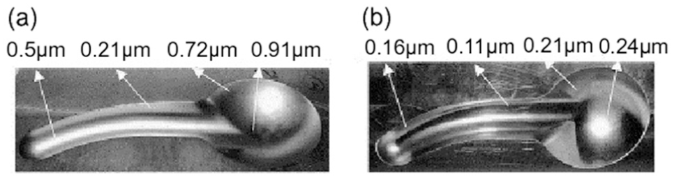
Mold cavity performed (a) without silicon and (b) with silicon powder for 100 min of polishing time. 90
Wu et al. 25 used a surfactant along with Al powder in the dielectric. This combination produced lower SR owing to uniform dispersion of powder particles in the dielectric. Pecas and Henriques97,98 analyzed the influence of powder concentration, electrode area and dielectric flow rate on the crater characteristics of the machined surface. Crater dimensions, that is, diameter and depth, decrease with powder concentration due to the dispersed multi-sparking in a single discharge. However, crater depth increases at high powder concentration levels due to an increase in discharge energy.
Micromachining
Recent advancements in micro-electro-mechanical systems (MEMS) and micro-mechanical equipment such as micro-pumps, micro-engines and micro-robots necessitate precise micromachining processes. Due to its capability to accomplish high surface finish, powder-mixed µ-EDM has resulted in better surface quality and precision compared to conventional µ-EDM.137,138 Chow et al. 23 machined micro-slits on titanium alloy using Al- and SiC-suspended dielectrics. It was observed that Al powder produced a large slit expansion due to its high electrical and thermal conductivities. A gray zone was found under the actual recast layer during the micro-PMEDM (µ-PMEDM) of Inconel 718 using Si powder due to its high heat of fusion. 24 Nanopowders of graphite, Al and Al2O3 were used by Jahan et al.9,69,71 during µ-PMEDM of WC10%Co alloy. No significant effect was found with Al2O3, while Al and graphite powders significantly improved the MRR and surface quality. Kibria and colleagues44–46 used boron carbide (B4C) powder in kerosene as well as deionized water during drilling of micro holes on titanium alloy. Diameter variation at entry and exit of the hole was more for kerosene dielectric than deionized water. At low peak current, such variation was more for powder-mixed dielectrics than pure dielectric, but less for high peak current.
Figure 10 shows the micro-slits fabricated by Chow et al. 7 on titanium alloy using silicon carbide–suspended pure water as dielectric. It was observed that the expansion of micro-slits was more for positive polarity.
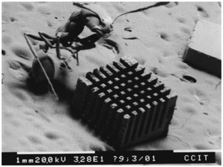
SEM image of micro-slits fabricated using SiC powder–suspended deionized water. 7
Surface modification
Electro discharge coating (EDC) using powder metallurgy tool has been used extensively for surface coating and modification. However, the surface becomes inaccurate due to high tool wear associated with the process. Surface coating and surface alloying using PMEDM have received much attention in recent years due to its improved accuracy.
Various researchers employed different powders mixed with dielectric to achieve a desired quality of the machined surface for specific applications. Chen et al. 120 improved biocompatibility of grade 4 pure Ti using PMEDM with Ti-mixed deionized water while employing reverse polarity and same Ti electrode. Formation of cubic TiO on the top surface was evidenced and thought to be responsible for its enhanced biocompatibility so that the EDMed specimen could be used as a dental implant. Due to its excellent lubricating properties, usage of molybdenum sulfide (MoS2) as an additive solved the problem of lubrication of EDMed sliding parts made up of stainless steel for space application. 139 Zain et al. 130 utilized tantalum carbide (TaC) powder during EDM of stainless steel (SUS 304) to achieve excellent surface microhardness. Bhattacharya et al. 10 studied the effect of various electrode and powder combinations on the microhardness of the machined surface. The results indicated that the combination of W-Cu electrode and W powder produced the hardest surface compared to the surfaces obtained by utilizing graphite and Si powder–suspended dielectrics. The investigation of Fong and Chen 11 on the EDM of SKD 11 steel revealed that Cr powder with low electrical resistivity and hardness has produced fine surface finish compared to SiC powder.
Furutani et al. 117 used different kinds of electrodes for the accretion of TiC on AISI 1049 carbon steel while adopting Ti-mixed dielectric. While a thin powder metallurgy electrode produced a high concentration of accretion of TiC, rotating gear shape electrode during PMEDM resulted in the accumulation of TiC over a large area. Urea was suspended in pure water during EDM of titanium to form a TiN ceramic layer. 135 Microhardness of the machined surface also increased due to the formation of such layer. Furthermore, surfaces machined using PMEDM process showed an improved resistance to corrosion due to effective surface modification. 89
Machining of nonconductive materials
Kucukturk and Cogun 70 produced holes on different nonconductive ceramics through EDM by suspending graphite powder in the dielectric. Before machining, all the workpieces were coated with a conductive layer to initiate the sparking. After the erosion of coated layer, the discharge process still continues due to the formation of a thin layer consisting of decomposed carbon particles of the dielectric, graphite powder and particles of the coated layer adhering to the machined surface.
Variants of PMEDM
PMEDM process is further improved by making small adjustments to the setup. Some of those variations are discussed below.
PMEDM with the rotary tool
The effect of the powder particles on the machined surface can be enhanced by using a rotary tool. Powder particles from the surroundings are dragged into the machining zone due to the centrifugal force of the rotating tool.140,141 This increase in the concentration of particles in the machining zone enhances the overall effectiveness of the powder particles.
PMEDM with ultrasonic vibration
MRR and surface quality can be improved considerably when ultrasonic vibration is imparted to the tool. More molten material is removed by each discharge due to enhanced abrasive action of the powder particles caused by the vibrating tool. SR also decreases owing to the wear out of the crater edges. 129
Instead of the tool, Prihandana et al.74,76 employed ultrasonic vibration to the workpiece in the forward–backward direction during µ-EDM process using graphite powder–suspended dielectric. Such vibration pumped out the debris from the IEG and allowed the fresh dielectric to flow into it, yielding better MRR compared to conventional EDM.
In another set of experiments, Prihandana et al.5,83 used an ultrasonic bath as shown in Figure 11, to vibrate the dielectric. This ultrasonic vibration of the dielectric reduces the adhesion of debris to the workpiece besides preventing the settling of powder particles at the bottom of the tank. The combined effect has resulted in the improvement of MRR, as more powder particles enter the IEG.
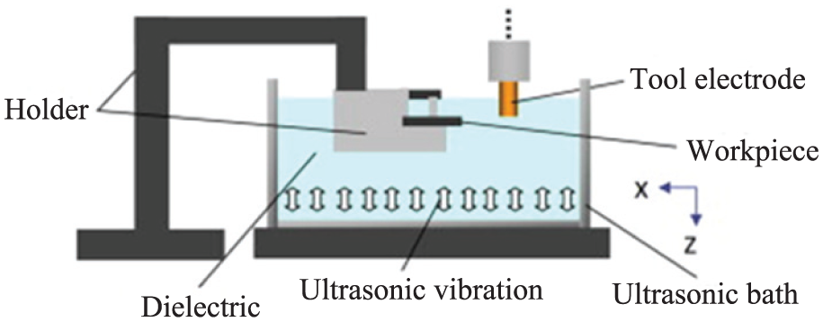
Experimental setup for ultrasonic vibration of dielectric. 83
Near-dry PMEDM
Very little work has been reported in the area of near-dry PMEDM. Debris removal is a primary concern in near-dry EDM. The enlarged discharge gap in PMEDM makes the way for easier debris removal thereby enhancing the process stability in near-dry PMEDM.142,143
Some of the major developments in PMEDM, starting from its inception, have been summarized in Table 3.
Evolution of PMEDM process.
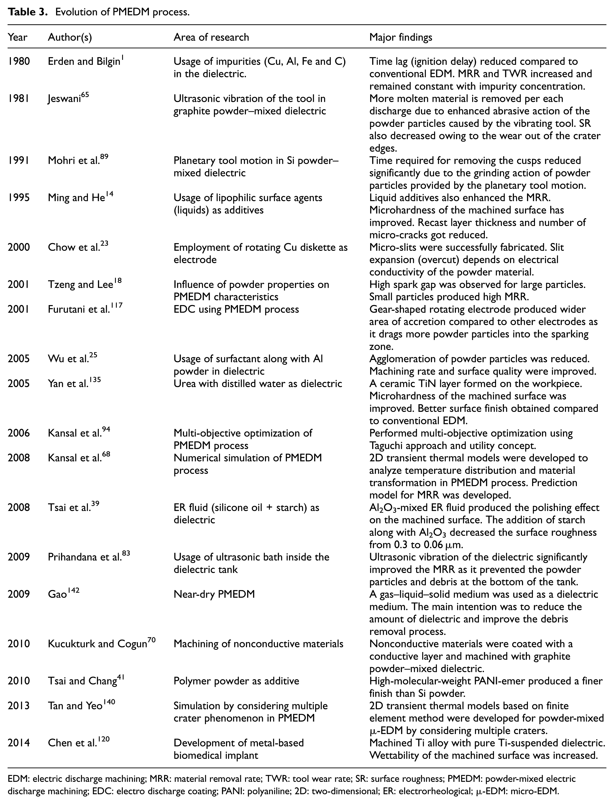
EDM: electric discharge machining; MRR: material removal rate; TWR: tool wear rate; SR: surface roughness; PMEDM: powder-mixed electric discharge machining; EDC: electro discharge coating; PANI: polyaniline; 2D: two-dimensional; ER: electrorheological; µ-EDM: micro-EDM.
Optimization of PMEDM process
Determination of optimal parametric combination in PMEDM process is more complex than conventional EDM due to involvement of powder additives in the former. Quite a few single objective optimization techniques in PMEDM were employed in the past using the design of experiment (DOE) methods such as Taguchi16,47,66 approach and response surface methodology (RSM).58,60,86
Bhattacharya et al. 63 performed a multi-objective optimization of MRR, TWR and SR during PMEDM of various steels using analytic hierarchy process (AHP) which eliminates subjectivity in the selection of response weights. Singh and Yeh 16 and Talla et al. 36 proposed, multi-objective optimization of PMEDM process during the machining of aluminum metal matrix composite using gray relational analysis (GRA) that has the advantage of dealing with incomplete information. Assarzadeh and Ghoreishi 43 carried out experiments using RSM-based DOE, and optimal parameter combination was determined using desirability approach which considers all the responses on an equivalent scale. A hybrid multi-response optimization employing TOPSIS (Technique for Order of Preference by Similarity to Ideal Solution) and GRA was performed by Tripathy and Tripathy 61 during the EDM of H-11 die steel using chromium powder–mixed dielectric. Padhee et al. 102 performed simultaneous optimization of multiple objectives using an evolutionary optimization technique called non-sorted genetic algorithm (NSGA). Multiple solutions obtained using evolutionary algorithms give the unique advantage to production engineer to select the desired optimal combination depending on the available resources.
Numerical modeling of PMEDM process
Substantial amount of the research work has been reported in the numerical modeling of EDM process. However, very few research works have been attempted in the numerical modeling of PMEDM process. Kansal et al. 68 developed an axisymmetric two-dimensional (2D) thermal model to predict temperature distribution with respect to various PMEDM process parameters. The model was further utilized to estimate crater size and subsequently the MRR. Along with temperature distribution and MRR, Bhattacharya et al. 72 accomplished a three-dimensional (3D) finite element model to predict thermal residual stresses induced during PMEDM process. Furthermore, mathematical models were developed to predict the radius and height of crater during PMEDM process. 75 Tan and Yeo 140 established 3D finite element models for surface integrity aspects such as maximum SR (Rmax) and recast layer thickness by considering multiple crater theory that gives more realistic representation of an EDM process. The influence of variation in powder concentration on the aforesaid surface integrity characteristics was also modeled. Similarly, Vishwakarma et al. 144 and Singh et al. 80 accomplished finite element models to predict MRR by considering single and multiple crater theories, respectively.
Challenges in PMEDM
Despite having many advantages, PMEDM has few challenges yet to be addressed.
Selection of proper dielectric and pumping mechanism is critical for smooth flow of powder particles in the IEG. Settling of powder particles at the bottom of the tank is a common problem.
In the case of surface modification, the amount of powder material needed is very high compared to other techniques thereby making the process expensive.
Separation of debris from the powder particles in case of anon-magnetic workpiece or when the powder particles are magnetic remains a concern. The process is less environmental-friendly compared to conventional EDM.
TWR increases in case of tool vibration and/or rotation due to the increased abrasive action. Selection of suitable high-strength tool material is important.
Conclusion
A detailed study and critical review of the work have been carried out in the area of PMEDM. Some of the observations of this study are summarized as follows:
Powder properties such as density, electrical conductivity and thermal conductivity influence the PMEDM characteristics significantly. The combination of low density, high electrical and thermal conductivities produce good machining rate and superior surface quality.
Si, Al and SiC are very widely used as powder additives. Good results, easy availability and low cost are the reasons for their usage. CNTs have been used very rarely because of their high cost despite producing splendid results due to their low density and high electrical conductivity.
Kerosene and some commercial EDM oils are most frequently used as dielectric fluids due to their high flash point. Deionized water was also used depending on the workpiece or when carbide formation on the machined surface had to be avoided.
For PMEDM, positive polarity has produced better results in case of finish machining. Deposition of powder material on the workpiece is also more in case of positive polarity. Negative polarity is preferred for rough machining operations.
Among the control parameters, peak current, pulse-on time, duty factor, powder material and powder concentration have significantly affected the performance measures in PMEDM.
Emerging trends and future scope
Most of the research work in powder-mixed EDM focused on the improvement of MRR and surface finish. Very few researchers have analyzed the surface integrity aspects such as metallurgical changes, microstructural modification and phase change in the machined surfaces.
The effect of physical properties (type, size, shape) of powder particles and their optimal combinations for various dielectrics need a thorough investigation.
PMEDM of die/tool steel has been given primary research attention. However, the study on nickel-based super alloys, titanium alloys, metal matrix composites and hybrid metal matrix composites as work materials has been started very recently and more research is expected in the near future.
Research on machining of nonconductive materials using PMEDM process is at the preliminary stage. Further investigations in this area would extend the EDM process to many more industries.
Polymer powders were very rarely used as additives. So the investigation of PMEDM responses using polymer powder materials would be an interesting area of research.
Feasibility study of different gas and powder combinations along with working ranges of machining parameters is critical in case of near-dry PMEDM process.
Footnotes
Declaration of conflicting interests
The author(s) declared no potential conflicts of interest with respect to the research, authorship and/or publication of this article.
Funding
The author(s) received no financial support for the research, authorship and/or publication of this article.