
Abstract
A design system for hydrostatic spindle is presented in light of the dynamic synthesis, which is based on the laws of the fluid mechanics, engineering thermodynamics and rotor dynamics. The finite element theory and hydrostatic principle are integrated into the design process, which provides not only the analyses and determination of the stiffness and temperature rise of the hydrostatic bearing but also the dynamic performance optimization. The proposed design system was implemented through a hydrostatic spindle on ultra-precision machining tools with the flycutting process.
Introduction
Spindle is the main mechanical component in machining centers, which has a strong influence on metal removal rates and quality of the machined parts.1,2 Therefore, the design of spindle is the key step of the whole machine design. Compared with the ball bearing in spindles for milling, drilling, grinding and other applications, the hydrostatic bearing shows higher precision and damping, better crash tolerance and longer life. Because of the outstanding advantages, hydrostatic spindle develops rapidly in recent years. However, the design philosophy of hydrostatic spindle is different from the ball bearing spindle. The design is not only based on the mechanical principles but also fluid mechanics and engineering thermodynamics. Unreasonable parameter design will make bearing temperature rise sharply and bearing crash severely, leading to the spindle failure. Therefore, it is extremely difficult for the amateur designers to design the hydrostatic spindle.
Many authors have investigated the dynamic behavior of machine tool spindle-bearing system, both theoretically and experimentally. 3 Their research results showed that spindle dynamics were influenced by a large number of factors, including the mechanical behavior of structural elements that composes the machining tool such as holder characteristics, 4 spindle shaft geometry, 5 drawbar force 6 and the stiffness and damping provided by the bearing.7–9 As to the design and optimization of the spindles, Yang 10 analyzed the static stiffness to optimize a bearing span using two bearings and described the methods to solve the multi-bearing span’s optimization. However, the aforementioned researches considered only the limited factors affecting spindle dynamic characteristics, and the spindle design principles are generally based on the static-driven approach. But there are significant changes in system dynamics that occur during high-speed rotation, especially for the spindle with larger disk. Wang and Chang 11 simulated a spindle-bearing system with a finite element (FE) model and compared it with the experimental results. They concluded that the optimum bearing spacing for static stiffness does not guarantee an optimum system dynamic stiffness of the spindle. Shin 7 presented that the dynamic characteristics of the spindle system vary with speed-dependent changes in the bearing stiffness, affecting the chatter stability. Therefore, the dynamic performance of the spindle cannot be ignored during the design stage. This means that the spindle design should not only rely on the static performance but also from a dynamic point of view. Therefore, a hydrostatic spindle dynamic design system is developed and validated in this article.
The integral process of the hydrostatic spindle design contains the hydrostatic bearing design, the spindle dynamic performance prediction and the cutting performance forecast. However, in traditional design process, the designer mainly concerned with the hydrostatic bearing design, but slightly even ignored the dynamic performance prediction and the cutting performance forecast. This design method may lead to the spindle performance unsatisfactory or even failure. Therefore, a hydrostatic spindle design system, which integrates the hydrostatic bearing design, the dynamic performance prediction and the cutting performance forecast, is presented in this article.
The overall hydrostatic spindle design system is outlined in Figure 1. The laws of the fluid mechanics, rotor dynamics and cutting mechanics are integrated in the design process in this system. The purpose is to make the hydrostatic spindle design systematic and simplistic. It can realize the prediction of the influence of the design parameters on the dynamic performances and optimize the parameters in the design stage.
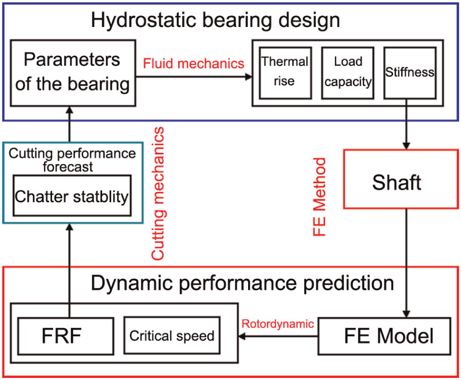
Outline of the overall hydrostatic spindle design system.
Dynamic design system of the hydrostatic spindle
The dynamic design system of the hydrostatic spindle is illustrated in Figure 2. The input of the design system is the initial structure parameters of the hydrostatic spindle; the output is the stiffness, load capacity, thermal rise, frequency–response function (FRF), critical speed and the chatter stability. The bearing damping is difficult to calculate accurately, so in this article, the value of the bearing damping is not considered, but replaced by a typical damping ratio of 0.03 for the hydrostatic spindle. The detail calculation process of the system is as follows: First, it calculates the hydrostatic bearing stiffness, load capacity and thermal rise according to the input structure size of the spindle based on the fluid mechanics, the specific calculation formulas are detailed in Zhong and Zhang. 12 Then, it predicts the dynamic performances of the spindle, such as FRF and critical speed by coupling the bearing stiffness calculated with the spindle shaft using the FE method. This step integrates the fluid mechanics and FE theory, by data sharing and transferring to achieve the organic combination of the numerical calculation of the hydrostatic bearing and the dynamic simulation of hydrostatic spindle. The specific integration process as follows: a spring element group generated by codes is introduced to represent the hydrostatic bearing stiffness calculated by fluid mechanics to improve the simulation accuracy. This spring element group is in accordance with the actual size of the hydrostatic bearing and can be adapted in the shape and size of the shaft with self-adapting process; this means that the spring’s stiffness will be varied with the bearing length and diameter used; at last, the chatter stability forecast is achieved according to the FRF and the specific cutting conditions. The obtained results provide a theoretical basis for the design parameter optimization. In this system, a direct link between the spindle structural size and dynamic performances is established, and a more intuitive response of the structural size on the spindle dynamic performances is given. It makes the optimization of structure parameters expedient and easy. In this design system, the influence of spindle structure size, diameter of the orifice, film thickness, oil pressure and characteristics of the oil parameters on the spindle dynamics are comprehensively considered. The proposed system is demonstrated by a hydrostatic spindle for flycutting machining.
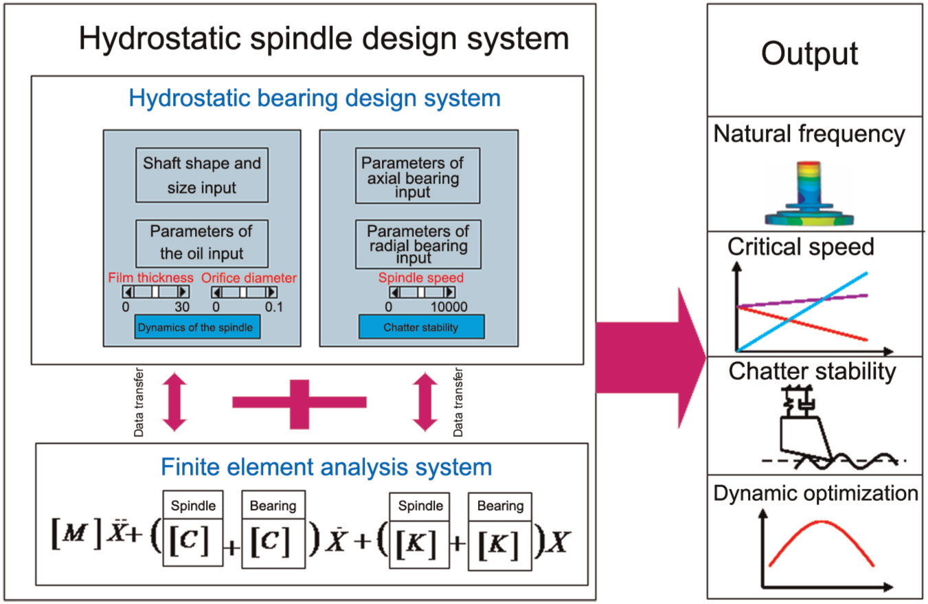
Hydrostatic spindle design system.
Implementation of the hydrostatic spindle dynamic design system
In order to achieve the ultra-precision machining for large flat parts, a hydrostatic spindle with a large cutting head is designed, as shown in Figure 3. Therefore, the dynamic performance of the spindle must be considered in the design stage. The shaft is driven by a brushless motor, which is placed in the rear of the spindle to reduce the thermal effects on the tool tip point. In order to use one oil supply system for the radial and axial bearings and easy to control the temperature of the oil tank, it needs the similar temperature rise in the radial and axial bearings. In this article, the temperature rise means the thermal generated by the friction power and pump power, and the conduction effects have not been considered. Therefore, the structure size of the spindle, diameter of the orifice and clearance should be optimized in the design stage.
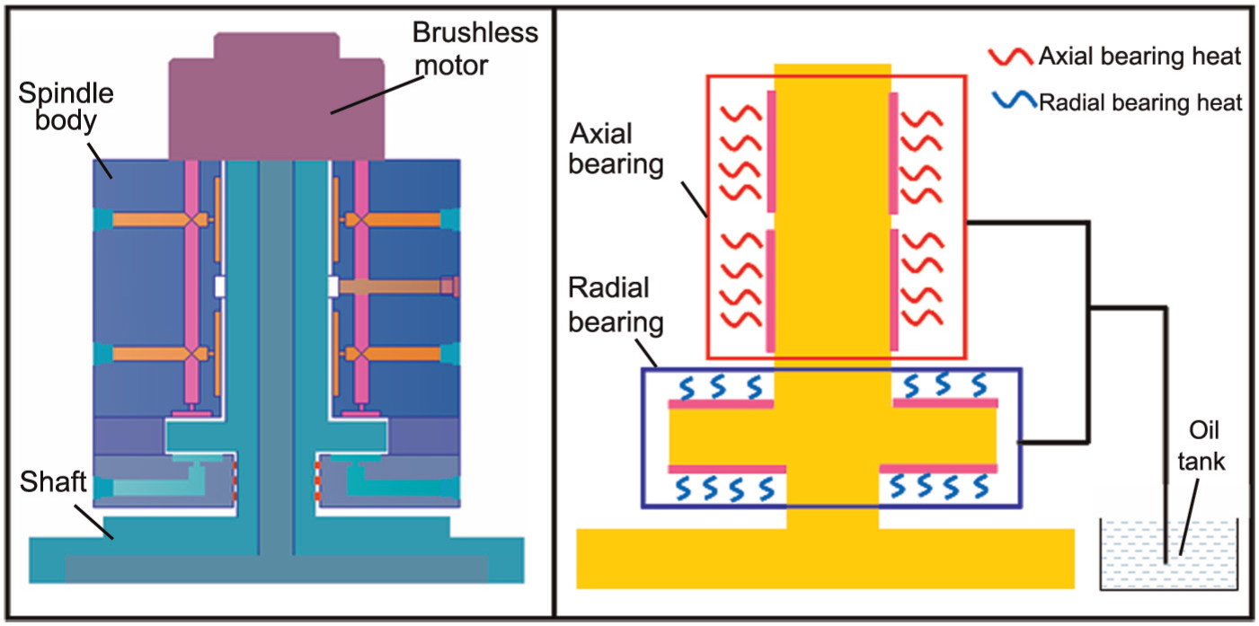
Structure of the hydrostatic spindle.
Modeling of the hydrostatic spindle
Due to the diameters of the shaft changes severely, the three-dimensional solid 186 elements are used to improve the modeling accuracy. The mesh density is controlled by the design system. Moreover, in order to consider the impact of cutting force on the dynamic performance of spindle, the cutting tool is included in the model. This new modeling approach is closer to the actual situation of hydrostatic spindle and can improve the modeling accuracy greatly. The FE model is generated by the design system, as shown in Figure 4.
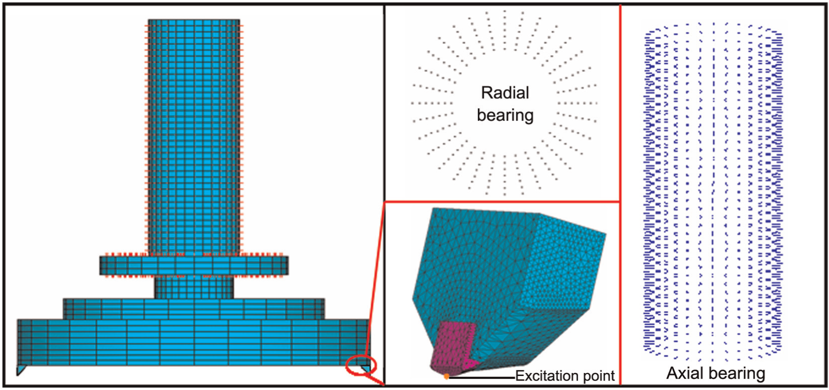
FE model of the spindle.
Dynamic performance optimization
The first five vibration modes are given in Figure 5(a) by the design system using FE method. They are the shaft swing around the top axis of the shaft, the shaft swing around the bottom axis of the shaft, the shaft swing around the axis of the thrust disk, the traverse up and down of the shaft and the radial expansion of the shaft, respectively. Each frequency is decided by the equivalent mass and stiffness. The equivalent mass is depended on the structure, size and material of the shaft. The equivalent stiffness contains the bearing stiffness and the shaft structural stiffness, which affect the low-order frequency and structural intrinsic frequency, respectively. The structural intrinsic frequency of the spindle cannot be changed, once the structure size and material are determined. However, the low-order frequency, which has mainly influence on the dynamic performances, can be optimized by selecting the appropriate bearing parameters such as clearance and orifice diameter. The hydrostatic design system gives the trends of the first five natural frequency changes with the clearance of both radial and axial bearings in Figure 5(b). With the increase of clearance, the first and the second mode frequencies increase first in the range of 10–16 µm, followed by the decrease. The fourth mode frequency increases first in the range of 10–13 µm. The first and second modes have the same trend because they are mainly affected by the stiffness of radial bearing, while the fourth mode is mainly affected by the axial bearings. The third and fifth modes are the structural intrinsic mode of the shaft, and they are only affected by the structure and size of the shaft, which has little relationship with the clearance and orifice size. It shows that the clearance values of axial and radial bearing for getting the optimal dynamic performance of the spindle are 15 and 16 µm, respectively. As shown in Figure 5(c), the influences of orifice diameter both of the radial bearing and axial bearing on the dynamics of the spindle have the same trend with the clearance. The design system also provides the trend of temperature rise with the change of clearance and orifice diameter in Figure 6. It can be noted that the temperature rises decrease with the increase of clearance and orifice diameter and have an abrupt decrease in 10–15 µm for clearance and 0.1–0.4 mm for diameter of the orifice, respectively.
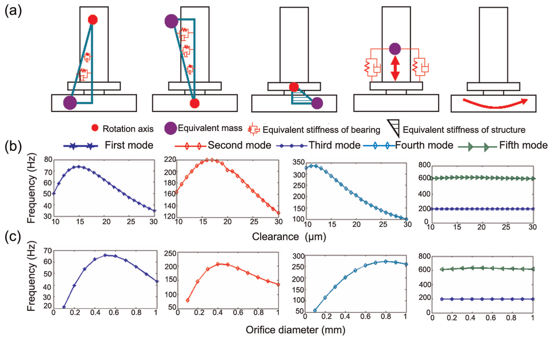
Dynamic performance optimization: (a) the first five modes of the spindle, (b) the influence of clearance on the dynamic performance of the spindle and (c) the influence of orifice diameter on the dynamic performance of the spindle.
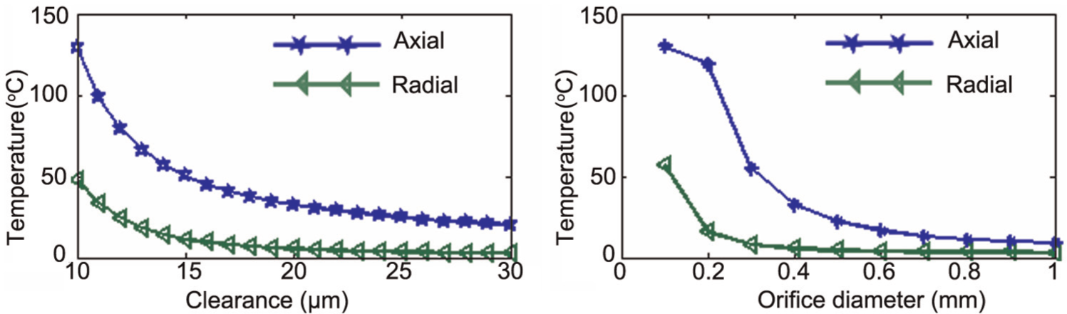
Influence of clearance and diameter of the orifice on temperature rise.
Critical speed and FRF prediction
Comprehensive consideration of the impact of the spindle dynamic performance, the temperature rise and manufacturing factors, the clearance of the radial and axial bearings is given as 15 and 16 µm, and the diameter of the orifice is given as 0.4 and 0.5 mm by the analysis of the design system, respectively. Those parameters not only meet dynamic performance requirements but also make the temperature rise similarly in axial and radial directions. Therefore, the same oil supply equipment can be used for the axial and radial bearings. In addition, the design system provides the critical speed of the spindle and the FRF based on the rotor dynamic analysis. The governing equation of motion in rotating frame of reference is
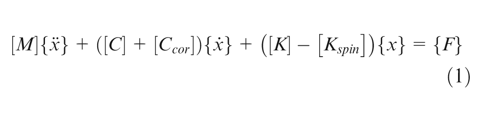
where [M] is mass matrix, [K] is stiffness matrix, [C] is damping matrix, [Ccor] is Coriolis matrix, [Kspin] is global stiffness due to centrifugal force (spin softening) and x and F are the nodal displacement and force vectors, respectively. In this theory, gyroscopic effect caused by the high-speed rotation is considered.
The Campbell diagram in Figure 7(a) illustrates that the critical speed of the spindle is 3500 r/min, which is eight times larger than the maximum operating speed (400 r/min), meeting the design requirement completely. Besides, there are only two natural frequencies occurring in the frequency range of 0–100 Hz, the maximum amplitude is 0.1 µm occurring in 63 Hz, which denotes a good dynamic performance of the spindle, as shown in Figure 7(b).
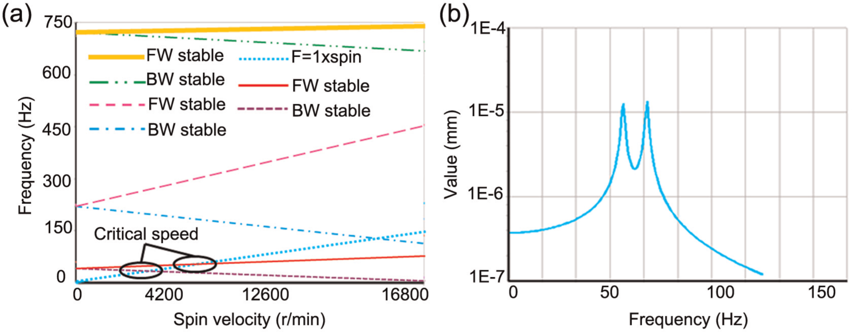
Rotor dynamic analysis of the spindle: (a) Campbell diagram and (b) harmonic analysis.
Chatter stability prediction
The design system also provides the calculation of critical depth of cut for chatter stability (blim) using the cutting chatter stability theory developed by Altintas and Budak 13
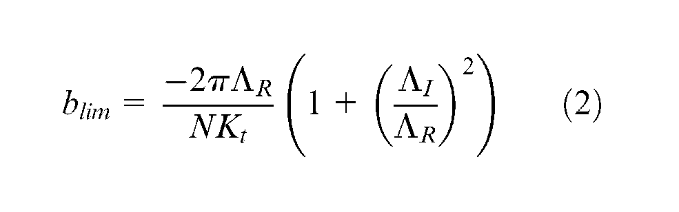
where Kt is the cutting coefficient, N is the number of teeth and
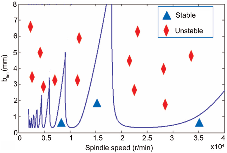
Stability lobes diagram.
Machining result prediction and validation
The prediction simulation for the dynamic design model is shown in Figure 9. The diamond cutting tool with nose radius of 5 mm is used in the simulation, as shown in Figure 9(a). According to the stability lobe diagram, the cutting depth is selected as 20 µm with 400 r/min. Figure 9(b) shows that the workpiece size is 415 mm, and the radius of flycutting head is 315 mm. Figure 9(c) gives the representative cutting forces and tool vibration over two revolutions. Figure 9(d) presents the waviness simulation result of the flycutting machining. It is shown that the vibration amplitude of the waviness is 6 nm, and the period is 25 mm. It can also be noted that the hydrostatic spindle has a good machining performance.
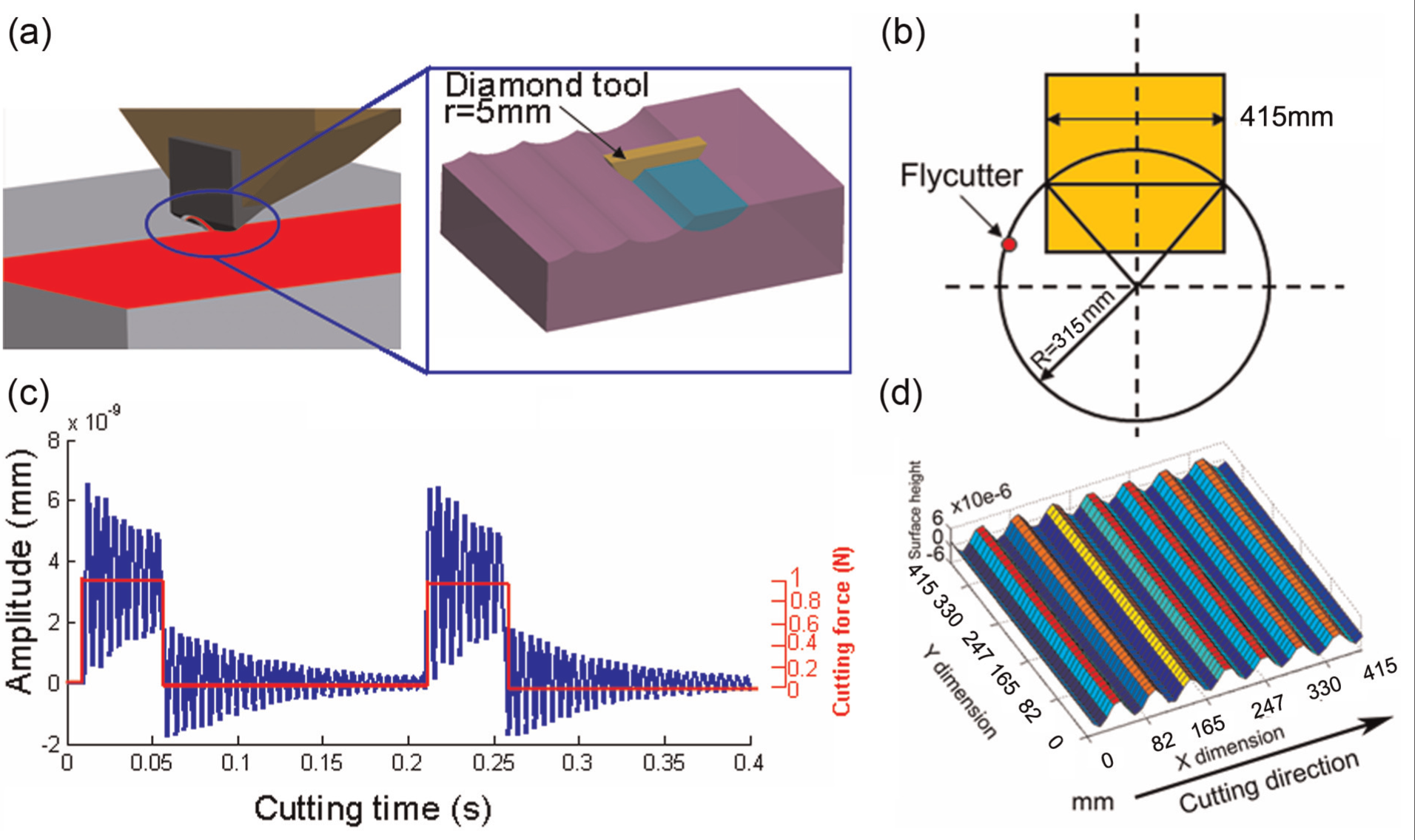
Cutting tool and the waviness simulation result: (a) cutting tool, (b) sketch map of cutting loci on surfaces, (c) the representative cutting forces and tool vibration over two revolutions and (d) the waviness simulation result.
Figure 10(a) shows the hydrostatic spindle mounted on the ultra-precision machining machine. The hydrostatic spindle is designed and implemented with the dynamic design philosophy. Figure 10(b) gives the machining result, it shows that the workpiece surface has the same waviness with the simulation result and the amplitude of the waviness is 10 nm, which is in accordance with the simulation result of 6 nm. This provides the evidence of the feasibility and effectiveness of the proposed design system.
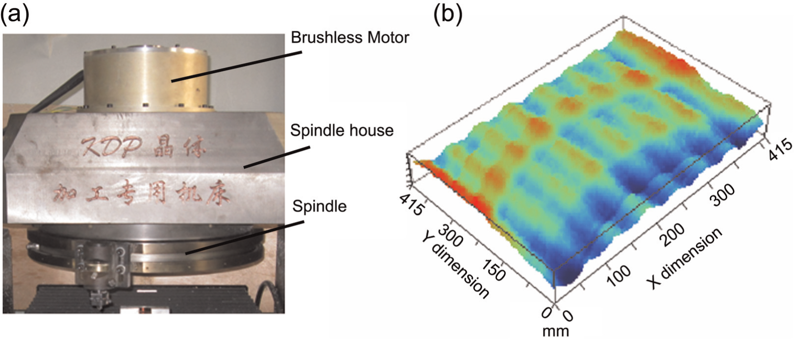
Hydrostatic spindle and machining result: (a) the hydrostatic spindle and (b) the machining result.
Conclusion
This article presents a hydrostatic spindle dynamic design system. It proposes an integrated method to achieve the hydrostatic spindle design. From the simulation and validation, the following major conclusions can be drawn:
A direct corresponding relation between the spindle structure and spindle dynamic performance was established based on the proposed system, and the design of hydrostatic spindle was achieved in terms of the dynamic point of view.
This design system achieves the parameter optimization design target to the dynamic performance and the thermal rise at the design stage, making the design parameter of the hydrostatic spindle more reasonable.
The machining results were forecasted by the system in the spindle design stage and verified by a hydrostatic spindle design used for flycutting machining.
Footnotes
Declaration of conflicting interests
The authors declare that there is no conflict of interest.
Funding
This study was financially funded by the National Science Fund for Distinguished Young Scholars of China (grant number 50925521) and National Science and Technology Special Program (grant number 2011ZX04004-061).