
Abstract
This article presents the dynamic design and thermal analysis of an ultra-precision flycutting machine tool. The hydrostatic bearings are used both in the spindle and slide to ensure the stiffness of the machine tool. The fluid–structure interaction method is used to obtain the actual clearance changes of the hydrostatic bearing. The dynamic and thermal performances of the machine tool are analyzed considering the effect of hydrostatic bearings. The influence of the thermal effect on the static and dynamic performance of the machine tool is further studied. The prototype machine tool is built. Preliminary machining trials have been carried out and provided evidence of fluid–structure interaction method being helpful to design the ultra-precision machine tool based on the hydrostatic technology.
Introduction
Precision machine tools are essential in the modern manufacturing field, which are widely used in the optical elements or precision mold machining. The performance of the machine tool is the primary issue during the design process since it directly affects the machining accuracy, repeatability, productivity, and efficiency.1–3 During the design of precision machines, the performance prediction is critical in the early stages of the design process, because 80% of the final cost and quality of a product are designed in this phase. 4 In addition, the changes and optimization in the later process have limited impact on the cost and quality.5,6
A great number of researchers studied the design method of precision machine tool. Huo et al.7-9 and Wardle et al. 10 developed an ultra-precision micro-milling machine tool based on a comprehensive integrated dynamics-driven design approach. For machining the special functional surfaces, Chen et al. 11 proposed a two-round design method for the ultra-precision machine tool design, during which the performance analysis of the machine tool and the surface generation simulation were well integrated, and the test software was used at the early design stage to estimate the machined surface. Homann and Thornton 4 proposed a precision machine design assistant tool, which used a combination of machine error motion modeling and constraint-based design methods. The tool can be used for the designer in the selection of a superior concept for detail design. Shore et al. 12 used a compact design method by reducing the overall machine dimensions to design a compact six-axes ultra-precision machining center, which was configured to offer compact size, eased automation, and in situ metrology. Weck et al. 13 studied the method used to reduce the deformations led by thermal drift displacements between tool and workpiece.
However, most of the previous design methods of the precision machine tool are from the views of the machine tool dynamic performance, or the errors reduction and compensation in the machine tool. Little of them concerned the influences of the thermal effect on the dynamic performance of the machine tool in the design stage. At present, in order to improve the stiffness and damping performances, the hydrostatic bearing is widely used in the precision equipment. However, the hydrostatic bearing always introduces thermal problem during the machining process due to the shear heat production of lubricating oil, which will change the stiffness of the bearings and affect the dynamic performance of the machine tool. Therefore, the thermal effect of machine tool should be considered carefully in the design stage.
In this article, a thermal-structural design method used for ultra-precision machine tool equipped with hydrostatic bearing is proposed. The fluid–structure interaction method is used to calculate the clearance changes of the hydrostatic bearing caused by the thermal rise of the spindle component. Besides, the influence of thermal effect on the static and dynamic performance of the machine tool is also studied.
The thermal–structural design method of ultra-precision machine tool
The thermal–structural design method is realized by integrating the fluid–solid coupling, thermal analysis of the fluid, and thermal-structural coupling. Its procedure is shown in Figure 1.
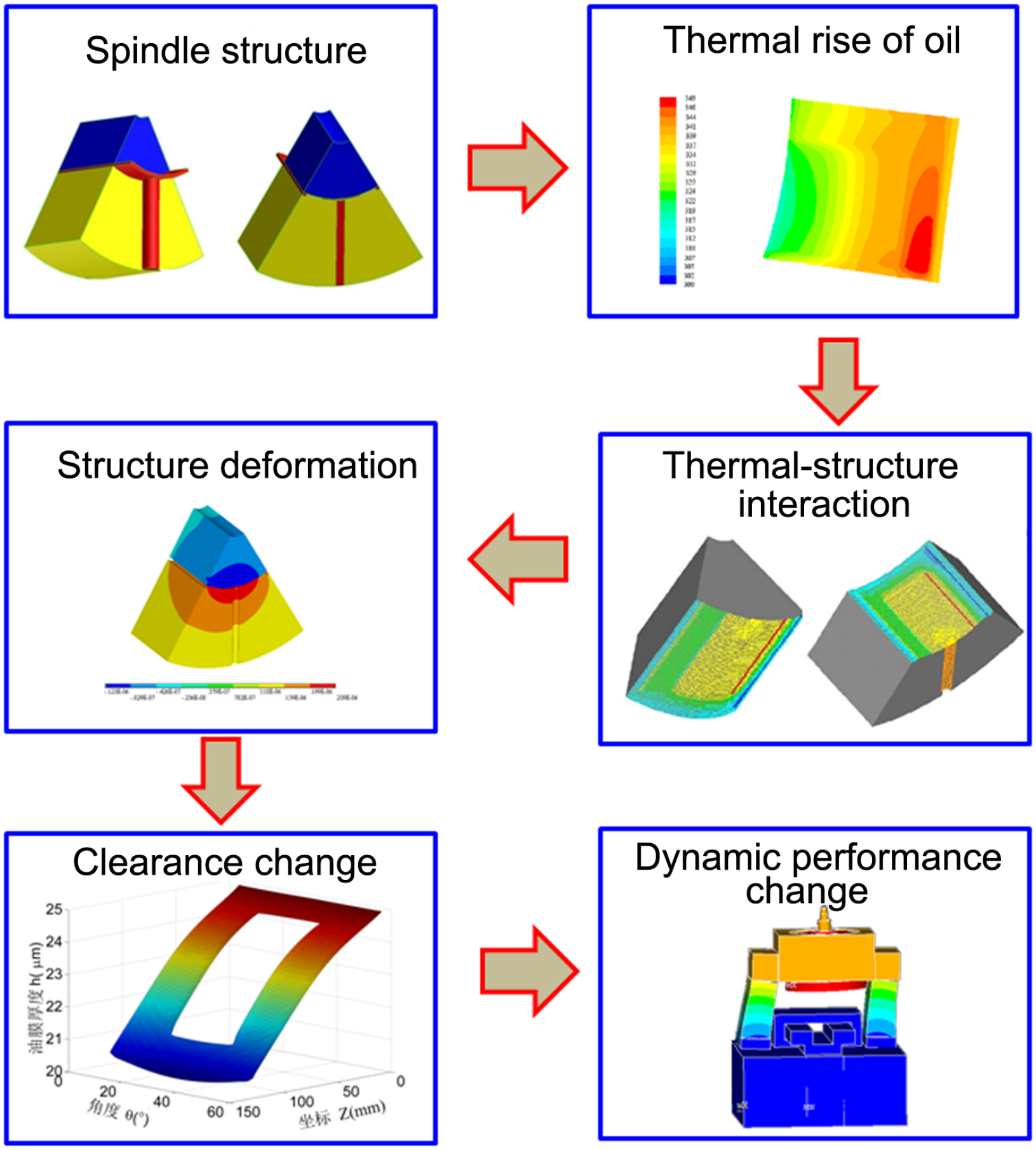
Procedure of the thermal-structural design method.
First, the thermal sources of the machine tool are identified, for example, the motor, the bearing, and then the structural deformations of the machine tool caused by the thermal sources are analyzed by the commercial finite element software Fluent and Ansys; then, the clearance change in the hydrostatic bearing caused by the structural deformations is obtained. Furthermore, the stiffness changes caused by the clearance are calculated. At last, the influence of bearing stiffness changes on the dynamic performance of the machine tool is analyzed by numerical methods.
An ultra-smooth surface machine tool design
The precision components with ultra-smooth surface (USS) are widely needed in the contemporary science and technology projects, for example, a large number of potassium dihydrogen phosphate (KDP) crystals are used in the Inertial Confinement Fusion (ICF) program,14,15 mirror substratum with USS is the core component of laser gyroscope.16,17
In the previous study, two generations of ultra-precision flycutting machine tool used for USS machining with aerostatic spindle have been developed by Liang et al.,14,15,18 but excessive waviness was found on the machined surface. 19 An et al. 20 pointed that the angular stiffness of the spindle had important influence on the waviness. Therefore, in order to further improve the stiffness and damping performance, a new machine tool with hydrostatic bearing is designed.
The configuration of the machine tool is shown in Figure 2(a). The moving components of the machine tool contain a rotation spindle and a slide. In order to further improve the stiffness and damping performances of the machine tool, the hydrostatic bearings are used in the spindle. The configuration of the hydrostatic spindle is shown in Figure 2(b). The viscosity of the oil is much higher than the air; therefore, unlike the aerostatic spindle, a significant amount of heat will be generated in the hydrostatic spindle rotation process. The thermal rise will cause the deformation of the machine tool structure, and then change the clearance of the hydrostatic bearing, which has important influence on the performance of machine tool. Therefore, the thermal effect must be considered in the precision machine tool design equipped with hydrostatic bearing.
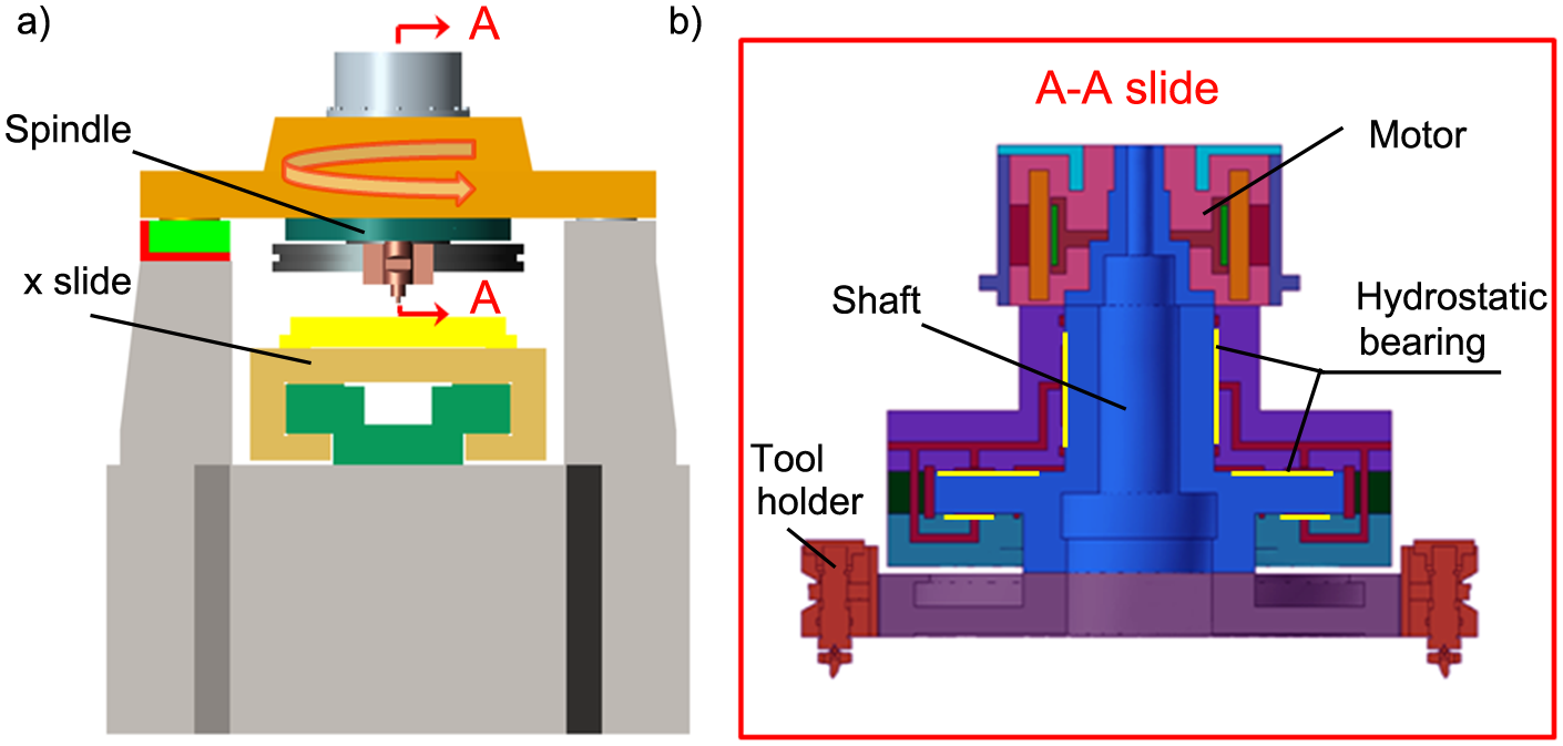
The hydrostatic flycutting machine tool: (a) configuration of the machine tool and (b) configuration of the spindle.
Thermal analysis of the spindle
The thermal sources of the spindle are the motor and the hydrostatic bearing of the spindle. The thermal model of the spindle is established. In order to simulate the heat generation process and liquid–solid conjugate heat transfer process in the hydrostatic spindle, the oil film and the solid structure of the spindle are both contained in the thermal model, which is built in the software Fluent. The motor of the spindle is set as a constant heat source, and the friction heat generation in the bearing is calculated by simulation of the spindle rotating process. The boundary conditions applied on this model are as follows: the inlet pressure is set as 0.5 MPa, the outlet pressure is set as atmospheric pressure, and the rotation speed of the spindle is set as 390 rpm. The thermal distribution and deformation caused by the thermal distribution are shown in Figure 3. From Figure 3(a), it can be found that the motor stator has the most significant temperature rise, nearly 6.5 °C, followed by the thrust bearing, nearly 5 °C. The motor stator is fixed on the motor shell and has no contact with the spindle shaft; therefore, it has little effect on the spindle deformation. The thermal rise of the thrust bearing has significant influence on the spindle structure (Figure 3(b)) and the spindle structural displacement caused by the thermal rise is shown in Figure 3(a). It can be noted that the thrust plate has the maximum deformation (nearly 11.6 µm), which may have important influence on the bearing stiffness.
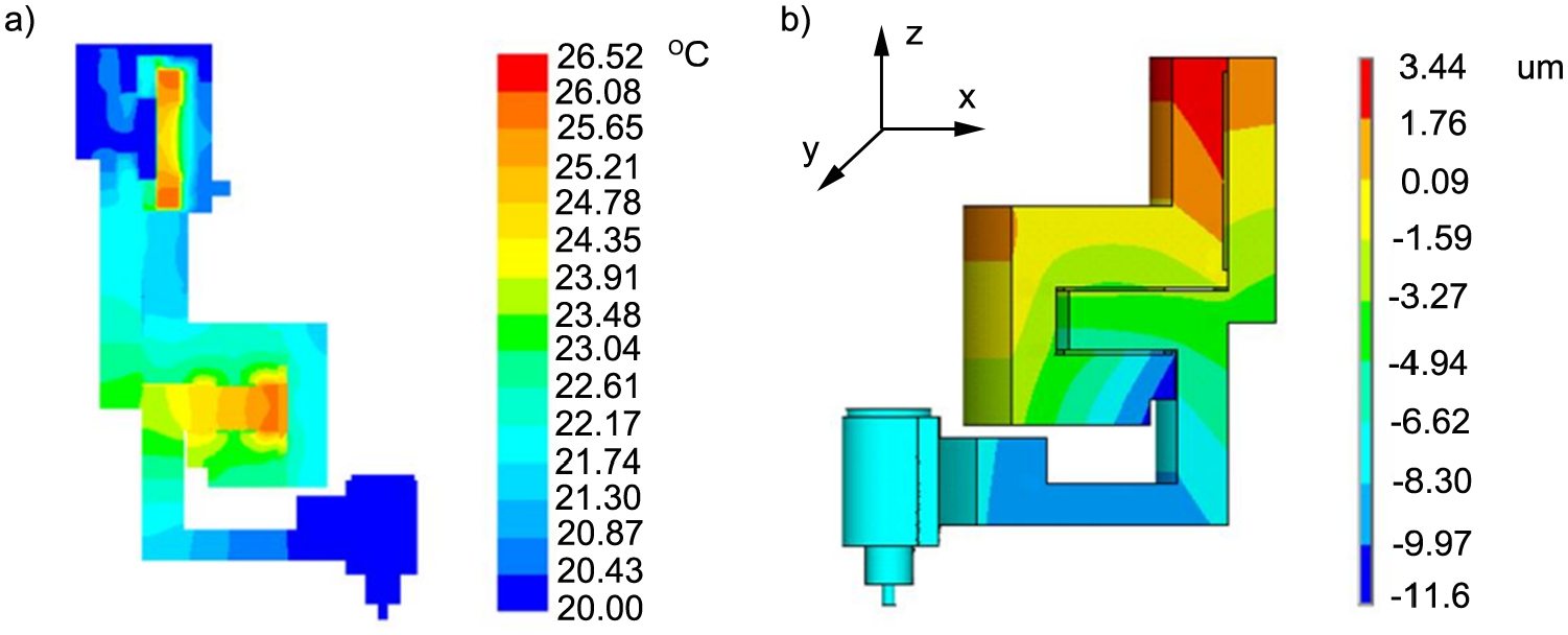
Thermal-structural analysis of the spindle: (a) thermal rise of spindle (t = 5 min) and (b) displacement due to thermal effects (t = 5 min).
The influence of thermal deformation on the bearing stiffness
After the finite element analysis of the hydrostatic spindle, the load capacity and stiffness changes of radial and thrust bearing caused by the thermal displacement are shown in Figure 4. It can be found that in the first 50 min, the stiffness of the thrust bearing has a dramatic decrease from around 4600 to 4050 N/µm, after then the stiffness remains stable. The radial bearing stiffness has a sharp drop in the first 20 min, which decreases from 475 to 325 N/µm, after then it has a slight decline and stable at around 250 N/µm. The main function of machine tool is to perform the flat surface machining and the z-direction is the sensitive direction; therefore, the stiffness of the thrust bearing has a large impact on the machined quality of the workpiece.
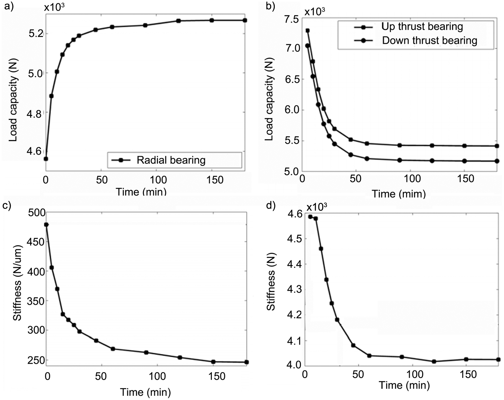
The influence of the thermal rise on the bearing performance: (a) load capacity of radial bearing, (b) load capacity of thrust bearing, (c) stiffness of radial bearing, and (d) stiffness of thrust bearing.
In order to obtain the dynamic response of the machine tool in the sensitive direction, for this machine tool is z-direction, the structure loop of the machine tool is illustrated in Figure 5(a), and the structure of the machine tool is simply idealized as a three spring–mass–damper system as shown in Figure 5(b). m1, m2, and m3 denote the mass of the beam, the spindle sleeve, and the rotor of spindle, which are 277, 243, and 484 Kg, respectively. k1, k2, k3, k4, and k5 denote the stiffness of the sleeve, hydrostatic bearing, beam, mount, and column, the value of k1, k3, k4, and k5 are 5.154e9, 6.803e9, 5.00e9, and 4.00e9 N/µm, respectively. The values of mass and stiffness of the above components are obtained by computer-aided engineering (CAE) techniques. 21 According to the above analysis of the influence of thermal deformation on the bearing stiffness, the stiffness value of the hydrostatic bearing k2 is changing with the thermal rise of the machine tool, which changes from 4600 to 4050 N/µm. c1, c2, c3, c4, and c5 represent viscous dampers of the sleeve, hydrostatic bearing, beam, mount, and column, respectively. Since it is difficult to obtain the specific value of them, a typical damping ratio of machine tool structure is used in this simulation, and the value is set as 2%. 22
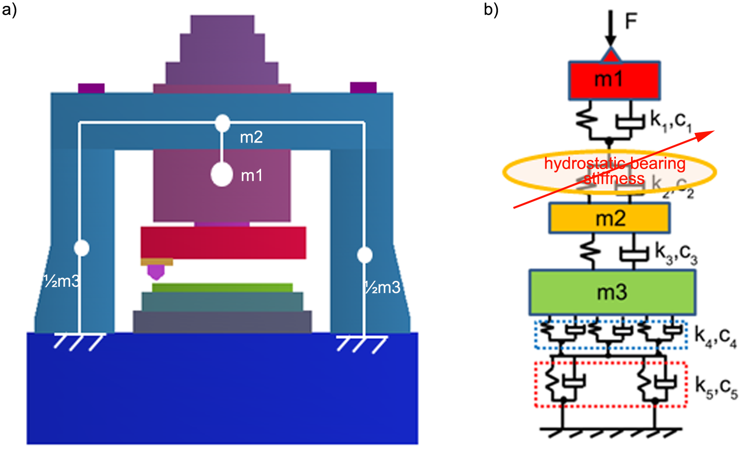
Dynamic model of the machine tool: (a) diagram of the machine tool and (b) a three degree-of-freedom spring–mass–damper system.
The mass matrix of the machine tool can be expressed as follows
The stiffness matrix of the machine tool can be expressed as follows

and the damping matrix of the machine tool can be expressed as follows

Therefore, the dynamic equation of the machine tool in sensitive direction can be given as follows

where
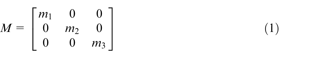
Figure 6 illustrates the dynamic performance changes of the machine tool in z-direction considering the thermal effect solved by MATLAB. It can be noted that with the thermal effect, the natural frequency of the machine tool declines from 375 to 330 Hz, and the response amplitude increases from 1.5 to 2.0 nm.
The influence of the thermal rise on the dynamic response of the machine tool.
Preliminary machining test
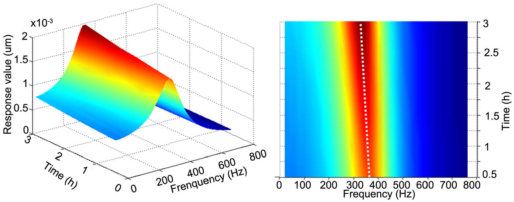
An ultra-precision machine tool based on the hydrostatic technology and thermal–structural analysis is designed for USS machining, and the physical machine tool is shown in Figure 7.
Ultra-precision flycutting machine tool.
In order to verify the effectiveness of the design method proposed in this article, the test of the influence of the thermal rise on the stiffness of the machine tool is carried out; furthermore, the machining test is carried out on this machine. The change of the thrust bearing stiffness with the thermal effect of the machine tool is tested, and Figure 8 presents the test configuration. The load is applied on the tool holder, and a capacitance displacement sensor with the resolution of 1 nm is used to test the displacement of the spindle. The capacitance displacement sensor is fixed along the axis of the spindle as shown in Figure 8. The thermal rise of the spindle is set as 0 °C, 8 °C, and 11 °C. The test results are shown in Figure 9. It can be found that the thrust bearing stiffness declines with the thermal rise of the spindle. With the thermal rise from 0 °C to 11 °C, the thrust bearing stiffness decreases from 4580 to 4050 N/µm, the values are agreed well with the simulation results, which contribute to the validation of the simulation method in this article. In order to reduce the uncertainty of experimental data, tests are carried out for five times, and the average value is used in this article.
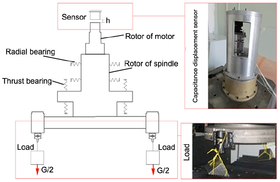
Schematic diagram of stiffness experiment and its equipment.
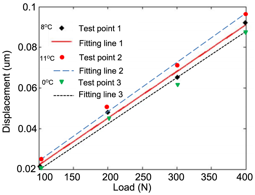
Stiffness test result under different thermal rise.
Machining experiments are also carried out with the material of the workpiece, aluminum alloy. The diameter of the workpiece is 120 mm, and the machined surface can be found in Figure 10. The experimental results are examined by a three-dimensional (3D) rough surface tester, Wyko RST-plus (Veeco Metrology Group) that is used to test the flatness accuracy of the machine surface. The measurement result with only tip, tilt, and piston removed is shown in Figure 11, and it is found that the flatness is 0.032 µm. The roughness of machined surface was measured by an atomic force microscope (Dimension Icon, Bruker corporation) as shown in Figure 12, and the test results show that the roughness of machine surface is 3.2 nm (RMS). The machined results indicate that the deigned machine tool using the thermal-structural design method has suitable machining ability for USS machining.
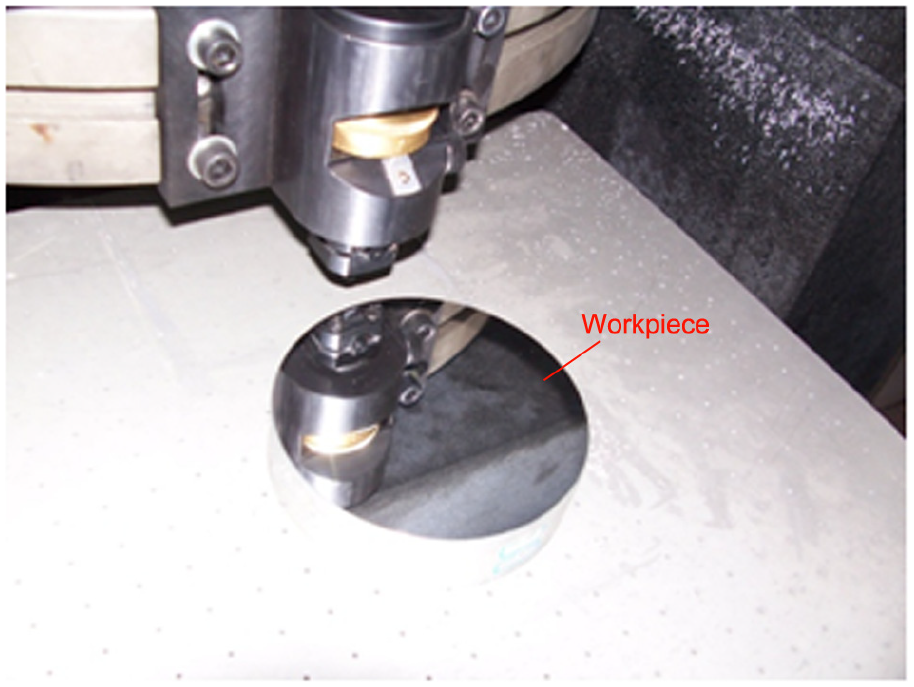
Machined workpiece.
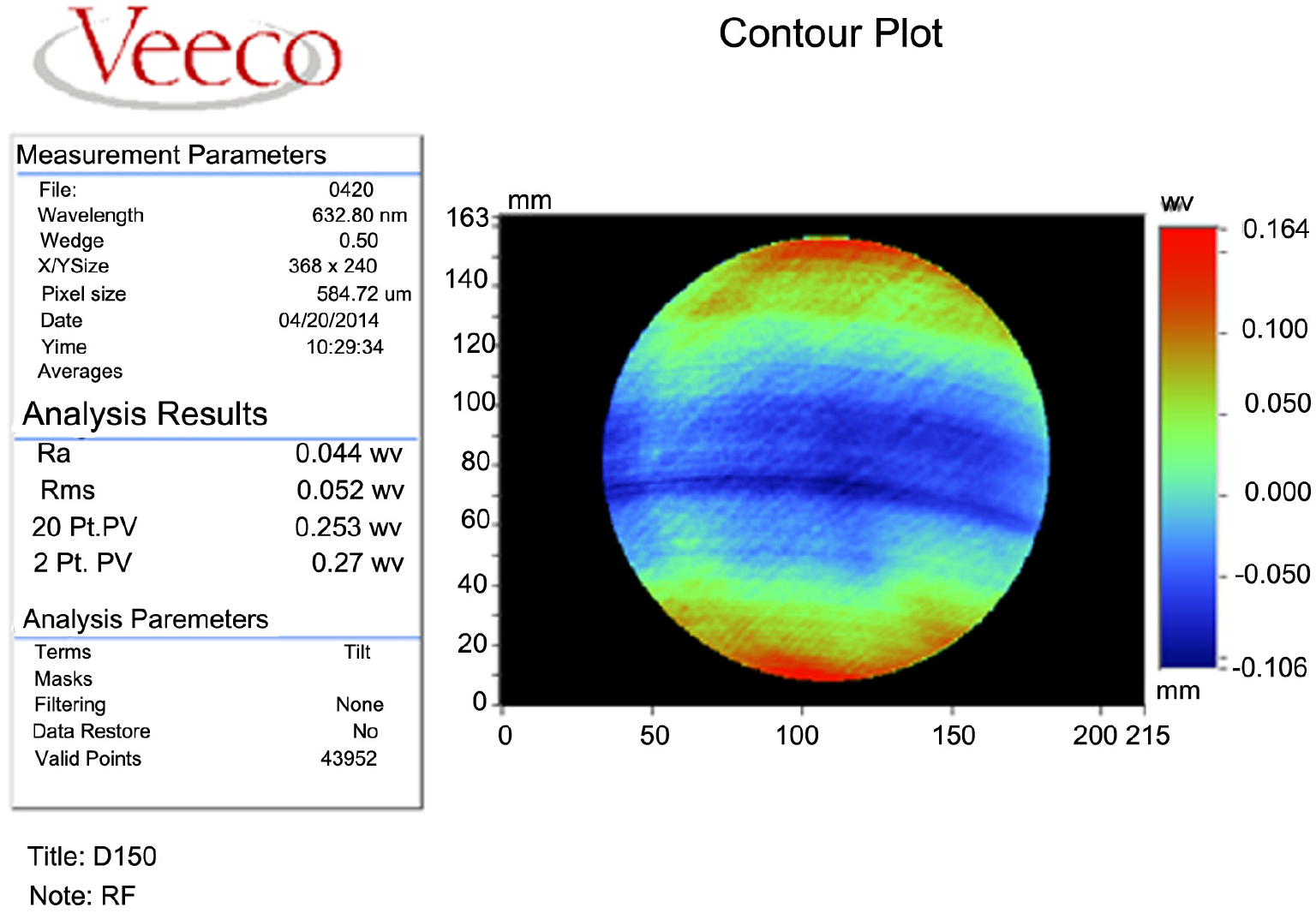
Flatness test result.
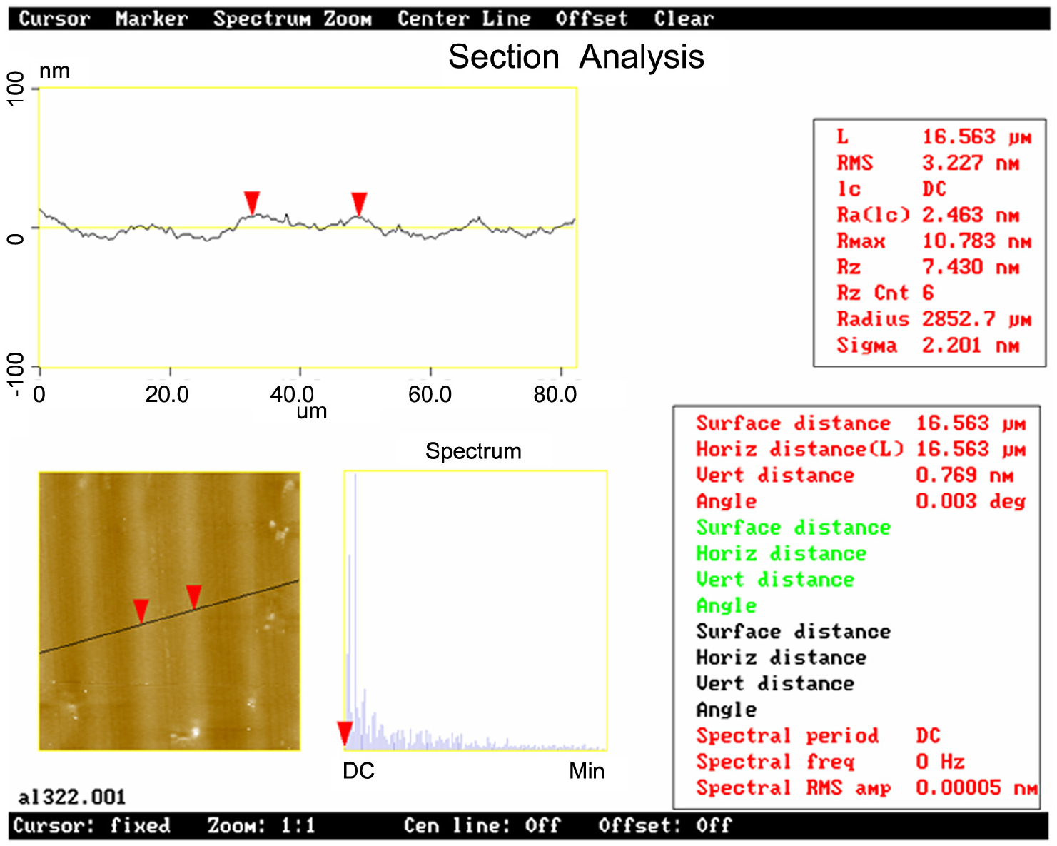
Roughness test result.
Conclusion
A thermal–structural design method of ultra-precision machine tool with hydrostatic bearing is presented in this article and an USS machine tool is designed considering the thermal effects. In terms of the presented results and discussions, the main conclusions drawn are as follows:
The thermal analysis of hydrostatic bearing is analyzed based on the thermal-structural simulation. It is found that from the view of the thermal analysis, the thrust bearing is more important than the radial bearing in the machine tool designed in this article, because the thermal deformation of the thrust bearing is larger than the radial bearing.
The thermal rise will change the bearing clearance and has important influence on the dynamic response of the machine tool. Considering the thermal rise, the natural frequency of the machine tool declines from 375 to 330 Hz, and the response amplitude is increased from 1.5 to 2.0 nm.
The stiffness tests validate that the proposed simulation approach is effective and efficient in the machine tool design equipped with hydrostatic bearing. The machining results indicate that the machine tool designed by the proposed design approach has excellent machining ability for USS machining.
Footnotes
Declaration of Conflicting Interests
The author(s) declared no potential conflicts of interest with respect to the research, authorship, and/or publication of this article.
Funding
The author(s) disclosed receipt of the following financial support for the research, authorship, and/or publication of this article: This work was supported by the National Natural Science Foundation of China (Grant No. 51505107) and Zhejiang Provincial Natural Science Foundation of China (Q16E050012).