
Abstract
Relative vibration between the cutting tool and the workpiece plays an important role in the surface generation in ultra-precision diamond machining. High-frequency vibration of the cutting tool has important influence on the surface roughness error, while the low-frequency vibration of machine tool structure affects the figure error. The previous related researches mainly focus on the first-mode frequency vibration of the machine tool. However, its multimode frequency vibration is rarely discussed. In this article, the multimode frequency vibration of the machine tool and its influences on the surface generation in flycutting are studied. The experimental results have been found to agree well with the simulation results.
Keywords
Introduction
Ultra-precision single-point diamond cutting has been widely used as one of the most advanced techniques for machining high-precision components with sub-micrometric form accuracy and super-smooth surface. 1 The ultra-precision flycutting is the main manufacturing method to generate optical quality surface on flat workpieces, 2 such as potassium dihydrogen phosphate (KDP) crystals which are widely used in inertial confinement fusion program. The morphology features of the machined surface have important influence on the components quality, the periodicities of which induce different mechanisms and differing degrees of crystal laser damage threshold. Many factors influence the surface morphology, such as machining conditions,3–7 material swelling and recovery,8,9 crystal orientation, 10 and mechanical vibration.11,12
Mechanical vibration plays an essential role in the performance of machine tools and machining processes, which directly affects the material removal rate, workpiece surface quality, as well as dimensional and form accuracy. 13 The vibrations of machine tools during cutting processes can cause the increase in tool wear, severe noise exposure, workpiece surface damage, which will limit cutting performance and productivity. Therefore, studying the vibration during the machining process is important to improve the machining performance.
Many researchers have experimentally and theoretically studied the effects of machine tool vibration on predicting and monitoring of the system stability in ultra-precision diamond machining (UPDM). Eric et al. studied the waviness on the machined surface of flycutting by a single-degree-of-freedom system; the results showed that the preferred spindle speed in ultra-precision flycutting should be chosen such that the dominant structural resonance did not occur at an integer multiple of the spindle speed.14,15 Abouelatta and Madl 16 used a regression method to find a correlation between surface roughness and cutting vibrations in turning. Wang et al. 17 investigated the tool-tip vibration and its influence upon surface generation in single-point diamond turning and proposed a geometric model of surface roughness to take account of machine tool vibration. Considering the important influence of the machine tool vibration, the first-mode frequency of the machine tool is designed as three times higher than the operational frequency in the “BOX” machine tool design. 18 Zhang and To 19 analyzed the effect of multimode high-frequency vibration of cutting tool (larger than 10,000 Hz) on the surface roughness of the machined components in ultra-precision diamond turning. Whereas the effect of multimode low-frequency vibration (less than 1000 Hz) of the machine tool on the surface generation of the machined components in UPDM was not mentioned.
Summarily, most of the previous studies focused on the first-order frequency vibration or the dominant frequency vibration of the machine tool. However, the other mode frequency vibration is not given enough attention in UPDM. Whereas multimode frequency machine tool vibration (MFMTV) has important influence on surface generation due to the error copying effect in single-point diamond machining. Therefore, studying the influence of MFMTV on the surface generation is necessary. In this article, the “experiment-observation-theoretical analysis-conclusion” strategy is adopted to study the MFMTV and its influences on the surface generation in UPDM. First, a series of machining tests are utilized to experimentally observe the frequencies of surface topographical patterns; second, the modal analysis is carried out to theoretically identify the multimode vibration frequencies of the machine tool. Finally, to study the influences of the MFMTV on surface generation in ultra-precision flycutting machining, an equivalent spring–mass–damper model integrated with surface generation technique is built to simulate the machine tool system.
Experimental details
In this study, a series of flycutting tests are carried out on a homemade ultra-precision flycutting machine tool.20,21Figure 1(a) shows the overview of ultra-precision flycutting machine tool employed for the cutting experiments. The spindle is supported by externally pressurized ultra-precision air bearings and driven by a direct current (DC) motor which can be rotated at 400 r/min. The work table is supported by hydrostatic slide which is driven by a linear motor with excellent slow feeding performance. Figure 1(b) shows the cutting direction and the feeding direction on the KDP crystal workpiece, whose size is 415×415 mm2. The machining tests are carried out under the following cutting conditions: depth of cut 15 μm, feed rate of 60 μm/s, and a spindle rotational speed of 300 r/min; and the tool parameters: tool rake angle of −25°, tool nose radius of 5 mm, and front clearance angle of 8°.
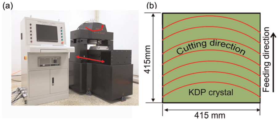
Machine tool system and the workpiece: (a) ultra-precision flycutting machine tool and (b) workpiece.
Due to the cutter rotation and large size of the workpiece, it is difficult to get the natural frequency during the machining process by force transducer. Fortunately, the machined surface can reflect the effect of machine tool vibration on surface topography directly in the machining process, so the machined surface measurement can be applied into tracing the vibration of the machine tool. Figure 2 shows a typical surface topography of an ultra-precision flycutting flat surface. In this study, the surface topography of a machined specimen is measured by the Wyko RST-plus (Veeco Metrology Group, Santa Barbara, CA, USA). The detection data of the surface topography are obtained as shown in Figure 2(a).
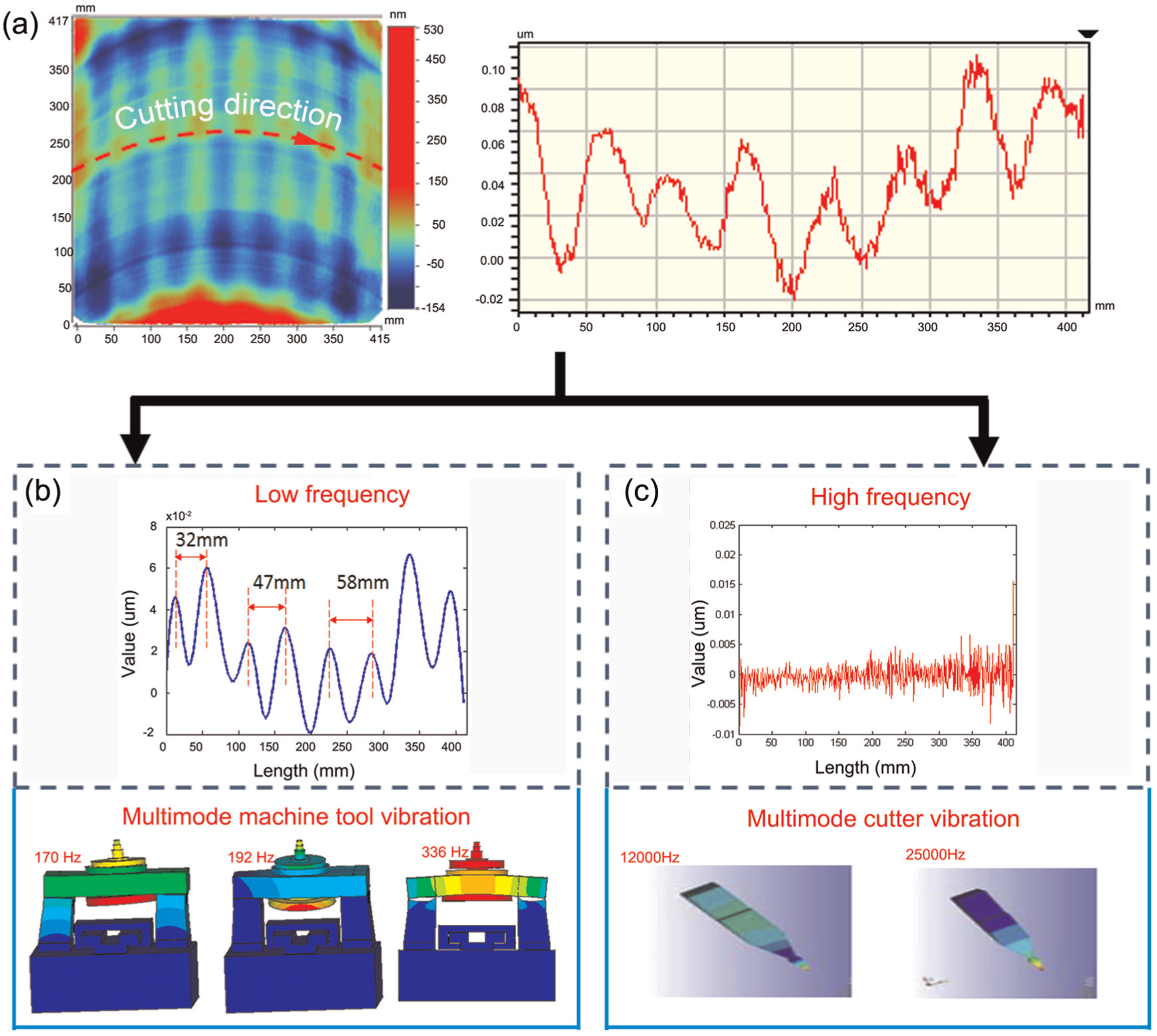
The vibration effect on the machined surface: (a) the test result of the machined surface, (b) low-frequency vibration, and (c) high-frequency vibration.
Result and discussion
Surface topography
It can be found in Figure 2 that the surface topography is formed by two components: low frequency with higher amplitude and high frequency with smaller amplitude. The low-frequency component in this study refers to the vibration introduced from machine tool, while the high-frequency component mostly comes from other factors, such as the elastic and plastic deformation of workpiece materials and the cutting tool vibration.22,23 After high-frequency filter, the low frequency with higher amplitude component on the machined surface is obtained, as presented in Figure 2(b). Additionally, the waviness periods are roughly about 30–60 mm. Therefore, the corresponding frequencies are about 330 Hz (f1 = 2π×r×5 rps/30 mm = 329 Hz) and about 160 Hz (f2 = 2π×r×5 rps/60 mm = 164 Hz); r is the distance from the cutting tool to the center of the spindle which is 315 mm. In order to obtain the multimode frequencies of the machine tool, the modal analysis of the flycutting machine tool is carried out by the finite element method (FEM) and it can be found that the first-, second-, and fourth-order natural frequencies are similar with the waviness frequency, which is 170, 192, and 336 Hz, respectively, as shown in Figure 2(b). Some relationships are found between the characteristics of the machined surface and the machine tool multimode vibration frequencies. Overall, the waviness with different periods is induced by the multimode frequency vibration in a certain range of the machine tool structure.
Theoretical analysis and modeling
The workpiece surface is generated by the relative displacement between cutting tool and workpiece. In this study, the workpiece is supported by the hydrostatic slide, whose stiffness in the cut depth direction is up to 4150 N/μm; therefore, the vibration of the slide can be ignored. The workpiece surface generation is mainly affected by the vibration of the cutting tool–related components of the machine tool.
From Figure 3(a), it can be found that the spindle shaft is held by the shaft sleeve which is fixed on the beam, and the beam is supported by two columns. During the machining process, the vibrations of the machine tool happen naturally due to external excitation from cutting forces. Since the machine tool material properties change along the structure loop as well as the machine structure, the stiffness of its cross section is also changed, so that various inherent frequencies exist.
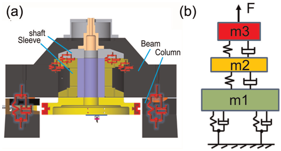
The dynamic system of the machine tool: (a) the structure of cutting tool–related components of the machine tool and (b) a 3-degree-of-freedom spring–mass–damper system.
In order to simplify the machine tool system, the machine tool structure is simply idealized as a three spring–mass–damper system. A single-point mass is used to approximate the machine tool parts mass which is generally distributed in the practical system. Similarly, a single spring is used to equivalent the elasticity of the machine tool, which is distributed throughout the machine tool system. Hence, the beam, the spindle sleeve, and the spindle shaft are effectively represented by masses m1, m2, and m3, respectively. As shown in Figure 3(b), the spring–mass–damper system is obtained to represent the machine tool system and to express dynamic response of the tool-tip in the cutting process; z1, z2, and z3 express the displacements of the spindle shaft, shaft sleeve, and the beam, respectively; k1, k2, and k3 denote the stiffness of the spring; and c1, c2, and c3 represent viscous dampers, which are obtained from the FEM results in the software ANSYS with Block Lanczos method.
Based on Newton’s second law, the state space modal equation for the 3-degree-of-freedom spring–mass–damper system is obtained as
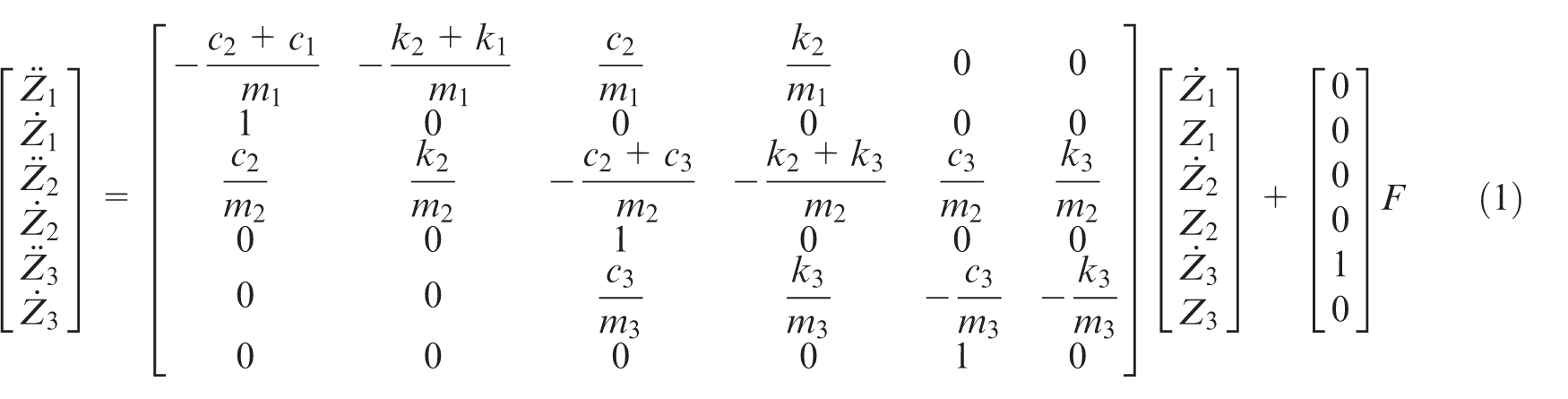
where
According to equation (1), the numerical simulation for the vibration response of the machine tool was done with a MATLAB Simulink model based on the Dormand–Prince method. The cutting force F in the simulation method is set as a rectangular wave with the duty ratio of 20%, amplitude of 1 N, and period of 0.2 s, as shown in Figure 4(a). In this simulation, the damping ratio is set as 2% for all modal vibration. The tool vibration response for z3 under the cutting force expresses the tool locus z(t), that is, the relative tool–workpiece distance, as shown in Figure 4(b). To analyze the characteristics of surface profile, the test data are transformed from the time domain to the frequency domain by the Fast Fourier Transform (FFT). The results of the frequency domain analysis for the machined surface profile are shown in Figure 4(c). It presents machine tool’s characteristic frequencies which are 163, 189, and 332 Hz, corresponding to the inherent frequencies of the machine tool, obtained from the surface detection. Also, the dynamic response of the tool vibration, z(t), is input into a surface generation model under the cutting conditions of the cutting experiment to generate the surface, as shown in Figure 5. It clearly shows that the waviness is formed at the simulated surface under the multimode frequency vibration of the machine tool, which agrees well with the experimental results.
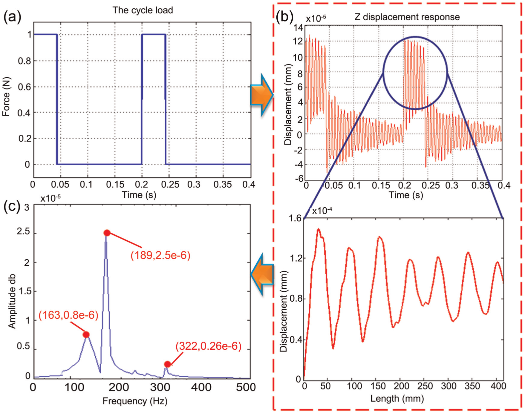
The simulation result of the theoretical model: a) Cutting force, b) Tool vibration response and c) The frequency domain analysis.
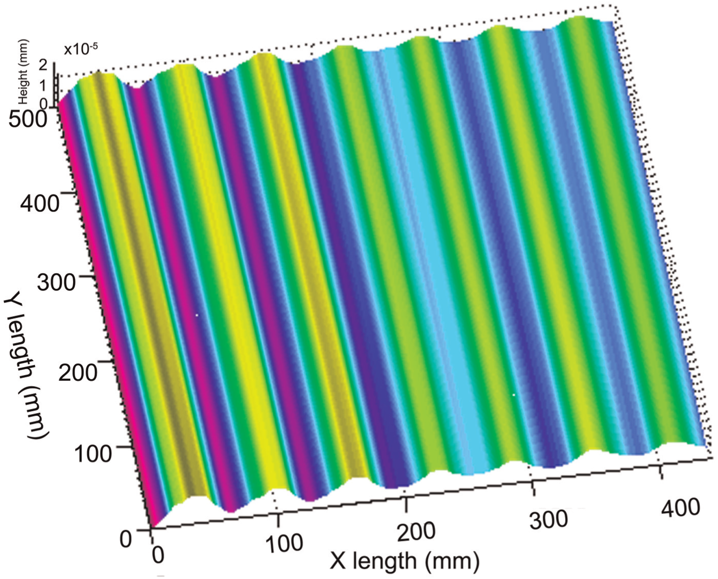
The simulation surface.
The simulated surface topography and the machined surface topography are shown in Figures 2(a) and 5, respectively. It can be noted that they have similar waviness period in the cutting direction, but different with the simulated surface as there are some rise and fall along the feeding direction on machined surface. This phenomenon is caused by the straightness error of the slide and fluctuation of the oil pressure in the machining process, which were neglected in the simulation model. 24 Furthermore, the damping radio for each mode is different in the real machine tool, but in the simulation model, the unified vale is adopted, which makes the amplitude of the waviness different between the test and the simulation results. On the whole, this simulation model is effective to predict the influence of multimode frequency vibration of the machine tool on the surface generation in the cutting direction.
Conclusion
In this work, the multimode frequency vibration of machine tool and its influences on the surface generation in ultra-precision diamond flycutting are discussed. It experimentally and theoretically indicates that the multimode frequency vibration of machine tool has important influences on surface generation in UPDM. The following conclusions can be drawn:
In the ultra-precision diamond flycutting machining, the machine tool vibrates at its multimode frequencies with large amplitudes, which have an important influence on surface generation. The waviness periods are roughly about 30–60 mm, which is introduced by the first-, second-, and fourth-order natural frequencies of the machine tool.
The surface generation prediction considering the multimode frequency vibration of the machine tool is conducted and validated by the experiment.
The developed theoretical model can be used to predict and analyze the effects of the MFMTV on surface generation in ultra-precision flycutting machining.
The cutter vibrates with the machine tool structure in the cutting direction and forms waviness on the machined surface; in order to obtain super-smooth surface, the multimode vibration needs to be suppressed.
Footnotes
Declaration of conflicting interests
The authors declare that there is no conflict of interest.
Funding
The authors gratefully acknowledge financial support of the National Natural Science Foundation of China (51105112).