
Abstract
In ultraprecision machining for microchannels, deformation occurs with high frequency because the diamond tool pushes against the channel structure during the machining process. Conservative cutting conditions decrease the cutting force and avoid deformation, but they reduce productivity. Therefore, it is important to select suitable cutting conditions in practice. This article presents a theoretical decision model for optimum machining conditions in manufacturing rectangular micropatterns. The model involves the prediction of cutting force and deformation. To forecast deformation phenomena, a rectangular pattern was considered as a cantilever beam with a distributed load, and the maximum principal stress that acts on the rectangular micropatterns could then be determined. For verifying this solution, several experiments were carried out to obtain a rectangular pattern by single-point diamond turning. Finally, the machining condition decision model was implemented and verified in practice.
Introduction
Recent advances in micromachining fueled by developments in the optics, displays, communications, electronics, and fuel cell industries have given rise to various techniques for fabricating complicated structures at micrometer scale. There is also a need for fabricating these complicated microstructures with high aspect ratios, such as microchannels. Several conventional methods, such as precision turning and precision milling, have been successfully used to fabricate microchannels, but many common methods still depend largely on semiconductor processing techniques, where silicon materials are photo-etched through chemical and dry processes, usually in large batches. These common unconventional methods are fabrication technique with polydimethylsiloxane elastomer, LIGA (lithography, electroplating, and molding), or microstereolithography. The majority of these methods are slow and limited to a few silicon-based materials. Moreover, the applications of these technologies are inhibited by low productivity, by the inability to manufacture in small batch sizes cost-effectively, and by the size to be machined and the surface roughness to be obtained.1,2
Micromechanical machining technology based on conventional cutting has advantages such as high productivity, low cost, and good surface finish. Therefore, recently, there has been strong interest in fabricating microchannels through mechanical cutting processes, that is, ultraprecision machining.3–6 These microchannels have been applied in a variety of areas such as privacy films, optical waveguides, compact heat exchangers, fluid distribution systems, hydrodynamic studies of microflows, chemical separation and analysis used in capillary electrophoresis systems, separation of biological cells, and DNA chips.
To manufacture microchannel structures using a mold obtained by ultraprecision machining, two types of fabricating methods can be employed. One is an injection-molding method, as shown in Figure 1, and the other is a roll-forming method, as shown in Figure 2.
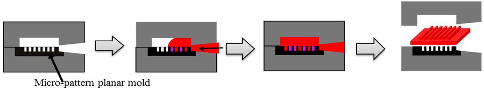
Micropattern injection molding.
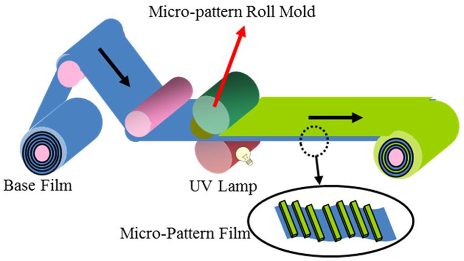
Micropattern rolling.
Micropattern-injection molding is suitable for producing plastic products such as Light Guide Panel (LGP), but there is a limit on the size of the product.7,8 The other manufacturing method, micropattern rolling, is a pattern-forming process in which metal stock is passed through a pair of rolls that have micropatterns on their surfaces, as shown in Figure 2. The compressive forces between the two spinning rolls act to reduce the thickness of the metal sheet, forming micropatterns on the surface and affecting its grain structure.
Both manufacturing methods have their own merits. However, micropattern rolling remains the best option because when a flat mold is used, significant time is lost during manufacturing. In comparison, a roll mold is able to achieve continuous fabrication, and thus, it is more efficient. Because roll molds are also suitable for large surface areas, in recent years, many channel structures have been produced using them. Roll molds are machined by ultraprecision diamond turning, for which two cutting techniques are available: thread cutting and plunge cutting.
Figure 3(a) shows the thread cutting method. It is generally used in turning operations because it drastically reduces the number of times the cutting tool must be moved back, and a great deal of machining time is thus saved. However, it is difficult to move the tool back to the original position of pass number 1; hence, there will be errors, leading to inaccuracy, blurring, and, possibly, deformation.
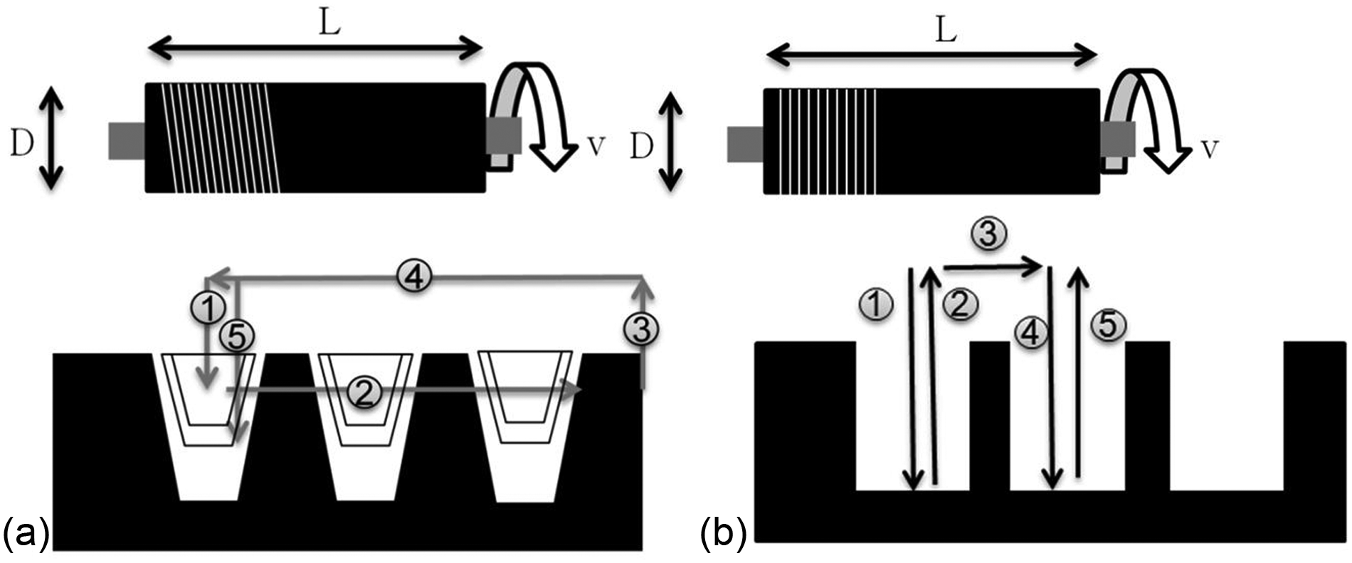
(a) Thread cutting and (b) plunge cutting.
For rectangular pattern manufacturing, the favored cutting mode is plunge cutting, as shown in Figure 3(b). This mode guarantees the precision of the pattern because it can reduce the positioning error.
Miniaturization and a high aspect ratio of microchannels are required to improve the performance and efficiency. However, microstructures can be easily bent while machining high aspect ratio and thin structures. Deformation phenomena are observed more easily when cutting forces are increased because of faster cutting conditions, as shown in Figure 4. This figure is the result of microchannel fabrication in microgrooving with different feed rates. The experiment was carried out in Korea Institute of Industrial Technology. It shows that when feed rate increases, deformation occurs and also becomes larger.
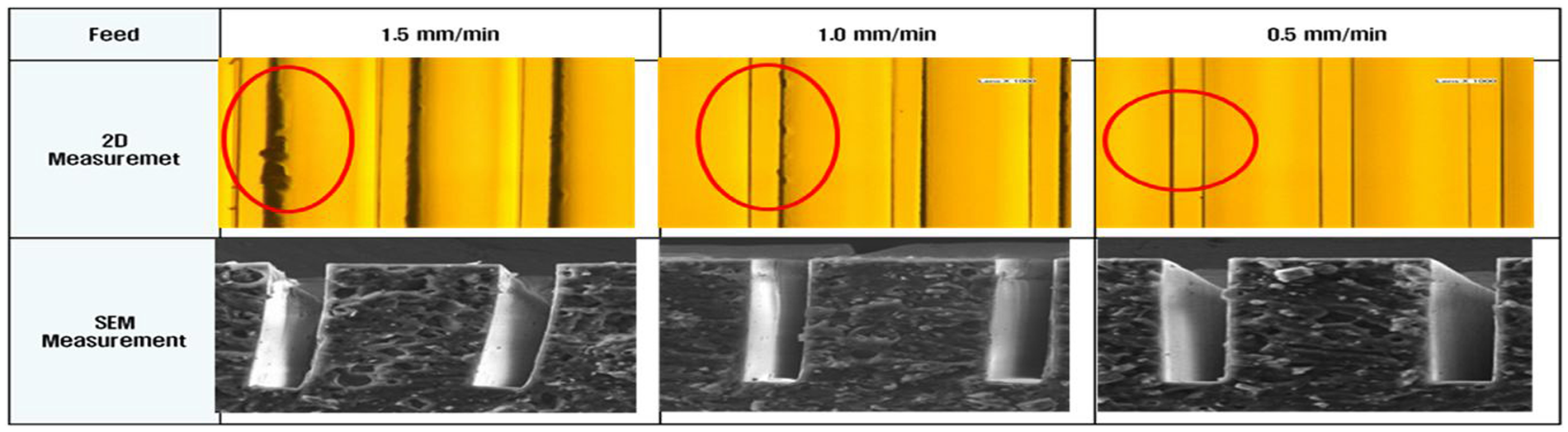
Deformation phenomena.
In ultraprecision machining, the cutting conditions are an important factor in determining the machining time; these conditions have a significant influence on microchannel deformation. That is, conservative cutting conditions decrease productivity, whereas excessive cutting conditions degrade the cutting accuracy by inducing excessive cutting force. Although it is important to select proper cutting conditions, as mentioned above, operators tend to decide on the cutting conditions from practical experience.
Therefore, it is essential that a theoretical model is developed that recommends the cutting conditions with a valid and acceptable method, so as to achieve high productivity without pattern deformation. To develop such a model, we produced a theoretical method for predicting cutting force and forecasting deformation phenomena for rectangular micropatterns with high aspect ratios; subsequently, optimum cutting conditions, which are cutting speed and feed rate, were predicted in ultraprecision diamond turning. A cantilever beam with a uniform distributed load model was applied to predict the maximum stress that leads to deformation. Furthermore, for evaluating this model, experiments with diamond cutting were carried out, and their results are discussed in this article.
Theoretical analysis
Cutting force analysis
In ultraprecision turning, cutting force is one of the main factors leading to deformation. Normally, the cutting force vector of the turning process is composed of three components: cutting force, thrust force, and radial force.
In orthogonal cutting, the Merchant model is the most common approach and is widely used in introductive courses on machining. According to Merchant’s development, for an uncut chip with height h and width b, the cutting force can be estimated with the following equation 9
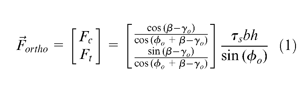
The friction coefficient β and shear stress τs are unknown, and only determined by means of experimental data. They are experimental constants and are determined for the purpose of minimizing the error between the measurement cutting force and the predicted cutting force. In our experiment, the minimum depth of cut is 2 µm, the noise radius of diamond cutting tool is around 50 nm, relatively smaller than 1 µm, and hence, there is no side effect and the rake angle γo is considered to be 0. The shear angle φo is determined by means of Ernst–Merchant’s prediction model

However, this model neglects the radial force and assumes it to be 0. One solution that has been developed is the dividing method. The cross section of the uncut chip is divided into several parts; each part is applied using Merchant’s theory to determine the local cutting force and local thrust force; and the total cutting force is determined by combining these local forces.
There are many ways to divide the rectangular uncut chip. Uncut chip can be split into two, three, or four parts. Because the cutting is achieved by means of three tool edges, the dividing method, as shown in Figure 5, in which three pieces are linearly divided, was chosen for our calculations. The different methods can lead to different cutting force components. The effectiveness of and differences between the various dividing methods will be discussed in a future article.
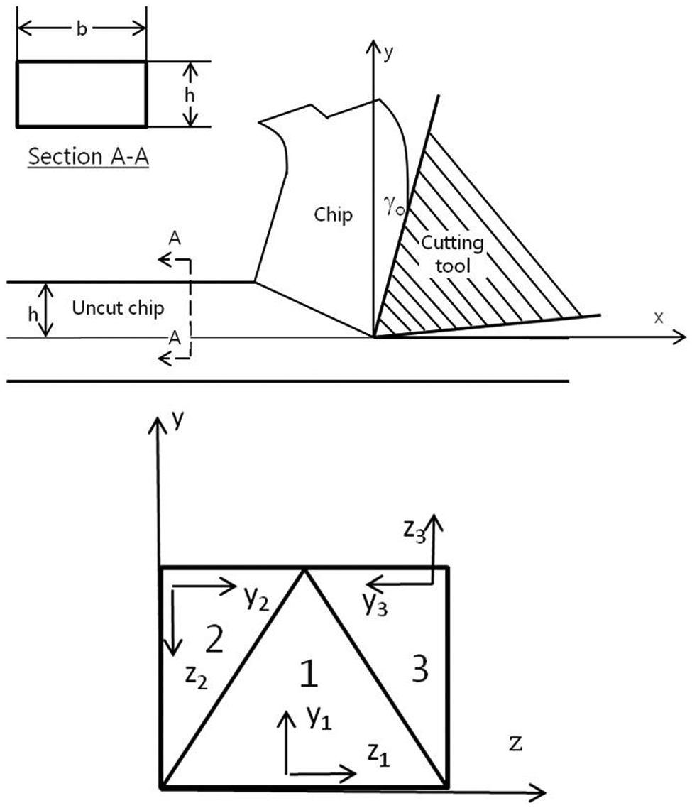
Cross section of divided uncut chip.
Piece no. 1 is calculated in coordinate axes x1y1z1, piece no. 2 is calculated in x2y2z2, and similarly, x3y3z3 is applied to the calculated cutting force on piece no. 3.
By following these rules, the total cutting force Ftotal can be expressed as
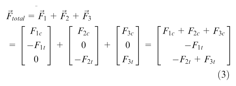
Moreover, the dividing method is symmetric; hence, piece no. 2 and piece no. 3 have the same area, so that
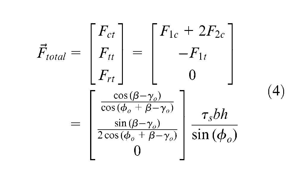
Ultimately, we obtain the same cutting force as with the conventional orthogonal cutting estimation, whereby the thrust force is reduced by half and the radial force still equals 0. However, with the dividing method, the force that acts on the side face of the groove can be estimated, and its amplitude equals the thrust force F2t or F3t.
Deformation analysis
In ultraprecision machining, there are several reasons for the occurrence of deformation. In our work, the radial cutting force, Fr, one of the three cutting force components, was considered to be a major cause of deformation. The radial cutting force creates a normal stress on the side face of the micropattern, which we call the side stress. Depending on how high this stress is, the micropattern can be deformed elastically or plastically. Moreover, during the cutting process, chip flows are not always vertical, and thus, chip formation will create a normal stress on the side of the micropattern. In addition, because the micropatterns have high aspect ratios, and cutting speed is relatively high, chips can become stuck in the microgroove and are unable to move out. The accumulation of these stuck chips will cause an impact on the side of the micropattern. For the sake of simplicity, in this article, we neglect the impacts of chip flows and only concentrate on the impact of the radial force component on the side of the micropattern.
For modeling, we considered the microchannel to consist of many rectangular thin plates, as shown in Figure 6. All plates have the same dimensions: height L, width h, and thickness b. During cutting step i of the machining process, the cutting tool edge moves along the x-axis, from 0 to Lw. In the case where deformation occurs, it grows along the microchannel, as shown in Figure 6. At the position of cutting edge x = b, the first thin plate is deformed with maximum deflection δi. When the cutting edge moves to position 2b, the second thin plate is also deformed. The same happens to the other plates. The interaction between these plates can reduce the possible deflection at the top of these plates. For the sake of simplicity, we assumed that there is no interaction between these plates, and they are deformed separately. Deformation from interaction between these plates will be discussed in a future article. Moreover, because all thin plates have the same dimensions, with no interaction between these plates and the cutting force is constant in one cutting step, the maximum deflection of the deformed plates will be the same value. Hence, the maximum deflection of a thin plate equals the maximum deflection of the micropattern.
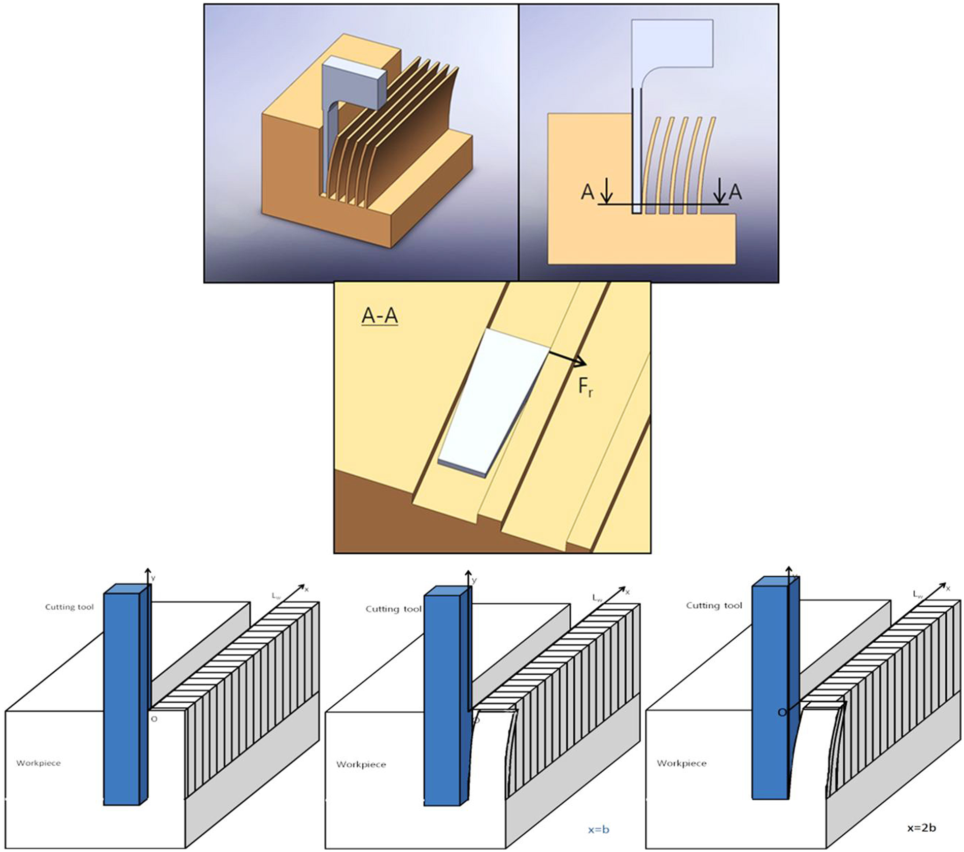
Deformation modeling.
Compared with its width and thickness, the height of a thin plate is normally significantly larger. Moreover, the radial force is perpendicular to the thin plate. In the case where deformation occurs, the bottom of the thin plate is laterally and rotationally fixed, and the top of the thin plate is free to move along the z-axis. All of these characteristics are similar to those of a cantilever beam. By rotating 90°, we can consider the thin plate as a cantilever beam, as shown in Figure 7. Moreover, the radial forces Fr can be considered as the distributed load ω.
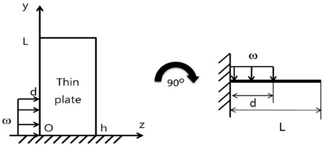
Thin plate is considered as cantilever beam.
As we considered in our cutting force analysis, in all cutting force components, there is a local thrust force of piece number 3 that acts on the side wall. Thus, to calculate the stress that acts on the micropattern, the thrust force, F3t, the component of piece number 3, is used. This force is converted to a uniform distributed load ω by the following expression

With distributed load ω, the maximum stress σmax on the micropattern can be calculated with the following equation10,11

On the contrary, the yield strength σy of the workpiece material is important in the prediction process. The yield strength is not only used to determine the type of deformation but also used in calculating deformation. Normally, for popular materials such as copper, steel, and aluminum, their yield strengths can be found in books or studies with little difficulty. However, because of the effect of size, the yield strength may not be the same as the value in these publications. Because of rapid developments in the materials industry, many new materials have been created, and, of course, their yield strengths cannot yet be found in publications. In our study, for acquiring yield strength with accuracy, a microindentation hardness test was carried out.
Optimum cutting conditions
Traditionally, the optimization of machining operations involves the selection of cutting conditions. The selection is left to the machine operator. In such cases, the experience of the operator is the most important factor, but even for a highly skilled operator, it remains difficult to attain the optimum values every time. In turning, the cutting conditions that need to be optimized are depth of cut, feed rate, and cutting speed. The setting of these parameters determines the quality of turned parts and the cost-efficiency.
Following the pioneering work of Taylor and his famous tool life equation, 12 various analytical and experimental approaches for the optimization of machining parameters have been investigated. Gilbert studied the optimization of machining parameters in turning with maximum production rate and minimum production cost as criteria. 13 Hinduja et al. 14 described a procedure to calculate the optimum cutting conditions for machining operations with minimum cost or maximum production rate as the objective function. For a given combination of tool and work material, the search for these optima was confined to a feed rate versus depth-of-cut plane defined by the chip-breaking constraint. Some of the other constraints considered include available power, work-holding, surface finish, and dimensional accuracy. Agapiou 15 formulated single-pass and multipass machining operations. Production cost and total time were investigated as objectives, and a weighting factor was assigned to prioritize the two objectives in the objective function. Agapiou optimized the number of passes, depth of cut, cutting speed, and feed rate in his model through a multistage solution process called dynamic programming. Several physical constraints were considered and applied in his model. In his solution methodology, every cutting pass is independent of the previous pass; hence, the optimality for each pass is not reached simultaneously. Most of the researchers in the area of machining have used various techniques for finding the optimal machining parameters for single- and multipass turning operations. Traditional techniques are not efficient when the practical search space is too large.16,17
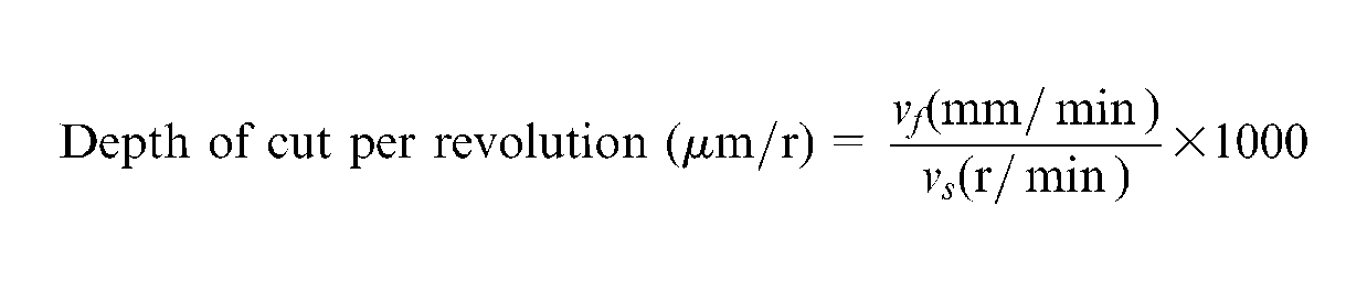
This article attempts to determine the optimal machining parameters for machining rectangular micropatterns on roll molds to minimize the production time and to avoid the deformation of micropatterns. In ultraprecision turning, the spindle speed vs (r/min) and feed rate vf (mm/min) are two main inputs in operating the turning machine, as shown in Figure 8. Few studies have examined the relationship between spindle speed, feed rate, cutting force, and deformation. To better understand these influences, we conducted several experiments with various spindle speeds and feed rates. The experiment setup and results are presented in the following section. The experimental results indicate that the variation of the cutting forces and pattern deformation depend mainly on the depth of cut per revolution, which is determined by the two cutting conditions. Therefore, to predict the cutting force and deformation, the “depth of cut per revolution” was defined with the following expression
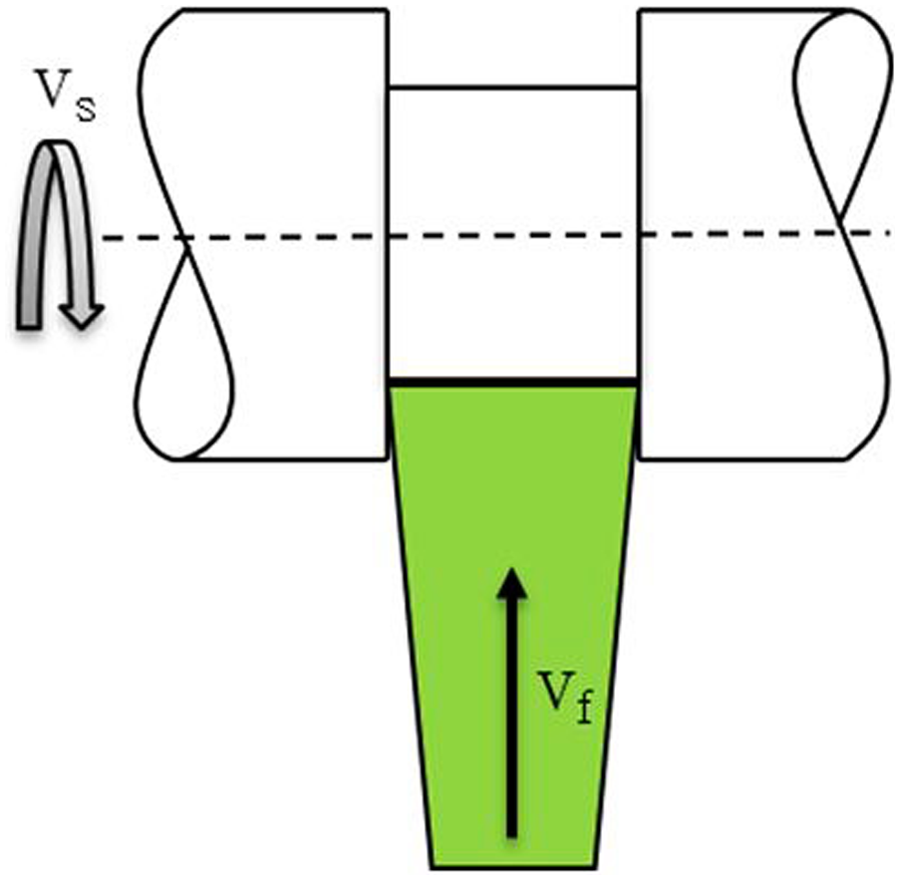
Two inputs for turning.
On the contrary, the cutting time for one slot can be expressed as

where h is the depth of cut or the height of patterns.
The material removal rate can be calculated as follows
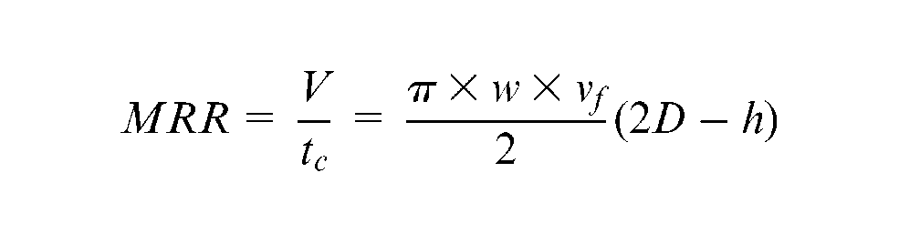
where w is the width of the tool.
In the above expression, the material remove rate mainly depends on the feed rate and not on the spindle speed. When the feed rate increases, the material removal rate increases. However, changes in feed rate or spindle speed also lead to changes in the depth of cut per revolution, which directly influences the strength of the cutting force. Moreover, if depth of cut per revolution increases beyond a certain value, the cutting force will cause the deformation of micropatterns. Therefore, the optimum cutting conditions must meet the following requirements: minimum machining time and no deformation. A flow diagram for determining the optimum cutting conditions is shown in Figure 9. The maximum side stress is considered as a final factor to decide whether the pattern deforms.
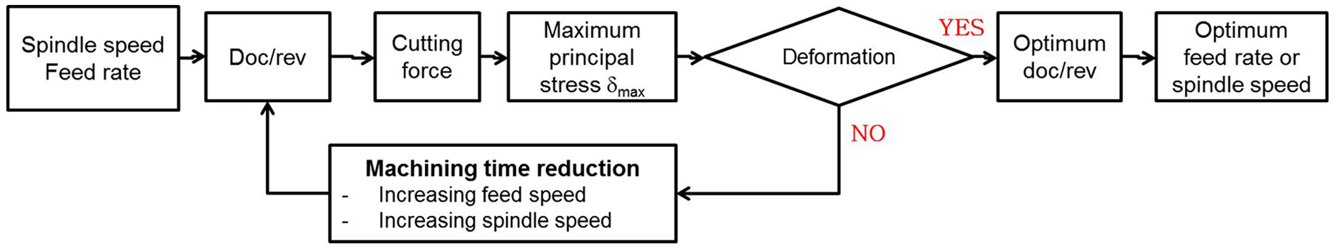
Flow diagram for determining the optimum cutting conditions.
Experimental results and discussion
Experimental setup
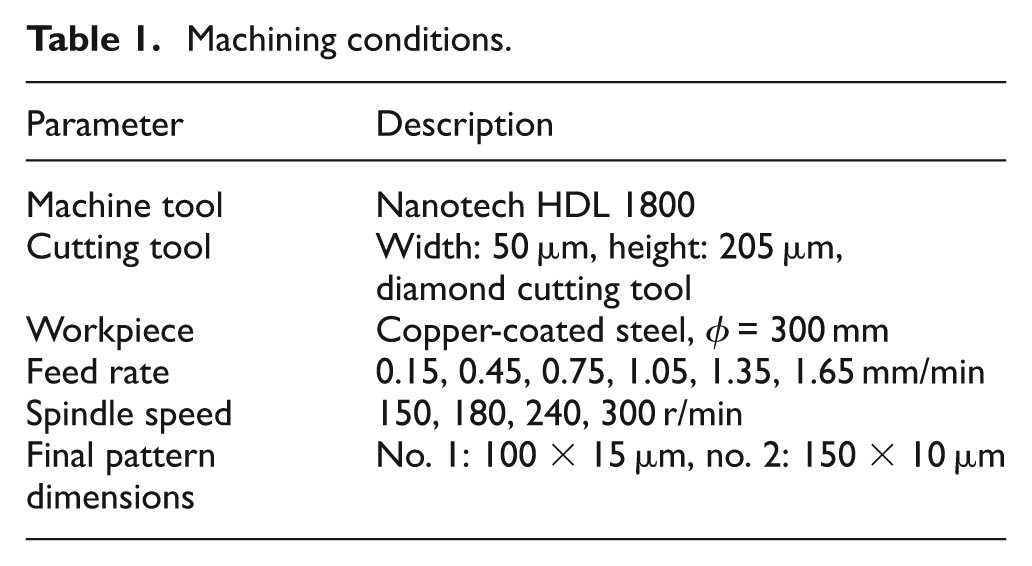
To validate our theoretical analysis, the cutting forces were measured and the states of micropatterns were checked. Machining conditions are shown in Table 1. The experiments were conducted with a machine tool Nanotech HDL 1800. The roll mold was made of steel with copper coating. A part of this roll mold was sent to FRONTICS Company for a microindentation test. The result showed that the yield strength of our roll mold approximates 374.4 MPa. The spindle speeds were from 150 to 300 r/min, and feed rates ranged from 0.15 to 1.65 mm/min. The cutting forces were measured with a Kistler dynamometer (type 9256C, with a 0.002-N accuracy threshold), and data were transferred to a computer through a DAQ card and LabVIEW, as shown in Figure 10. For each combination of feed rate values and spindle speed values, five rectangular micropatterns were machined. At the end of each cutting step, scanning electron microscope images of rectangular patterns were taken. Based on the above analysis, a MATLAB program was built to aid the prediction of cutting forces and the recommended cutting conditions. The experiments were separated into two groups with two final pattern dimensions. The micropattern shapes of each experimental group are shown in Figure 11.
Machining conditions.
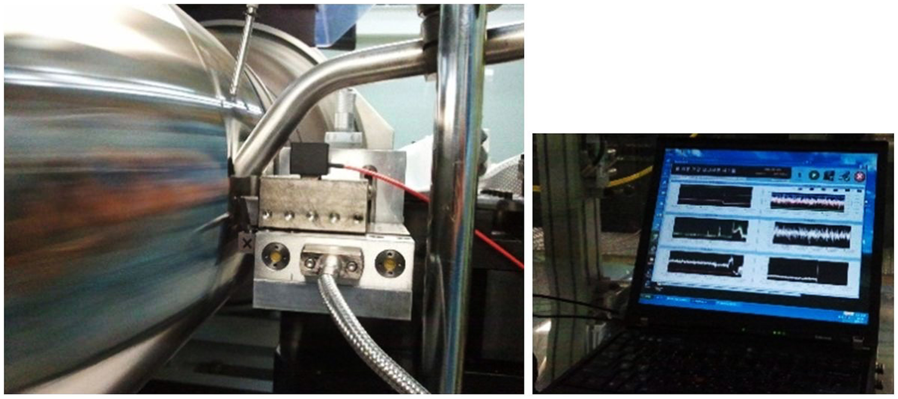
Experimental setup.
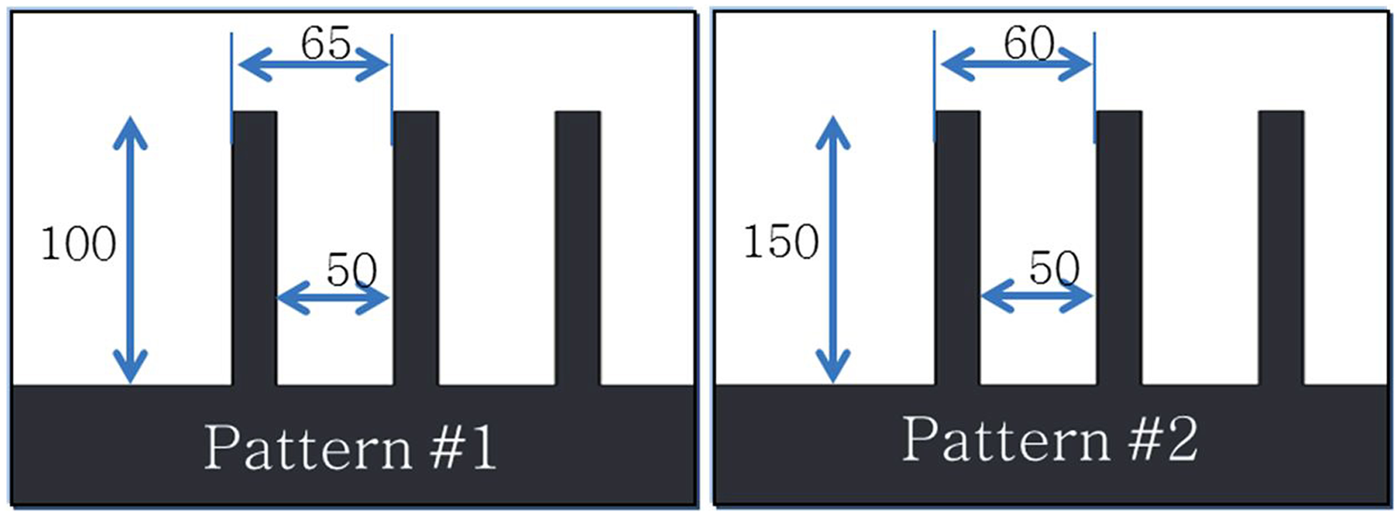
Final pattern dimensions of two cases used in verification.
Results and discussion
The relationship between cutting conditions and cutting force was obtained through the experimental results, as shown in Figure 12. The red circles in this figure indicate the case in which patterns were deformed. Both scenarios indicate that when feed rate increases or spindle decreases, the cutting force also increases. Moreover, when the spindle speed increases, the rate of increase of the cutting force decreases. This agrees with the theoretical analysis, in which increasing spindle speed means that depth of cut per revolution decreases, leading to decreasing cutting force. To determine whether patterns were deformed, two checking method were applied. First, the top view of the patterns was captured by using a camera with macro lens. On the contrary, the blue silicon molds were embedded in grooves, then scanning electron microscopy was used to capture images of these silicon molds. This method shows the reverse of side view of micropattern. Figure 13 shows the two deformation checking method. Among the results, in six cases of pattern no. 1 and in five cases of pattern no. 2, deformation occurred. Deformation always occurred when the cutting force increased beyond a certain value, which was approximately 0.58 N for pattern no. 1 and 0.42 N for pattern no. 2. This means that the cutting force was the main factor in the deformation.
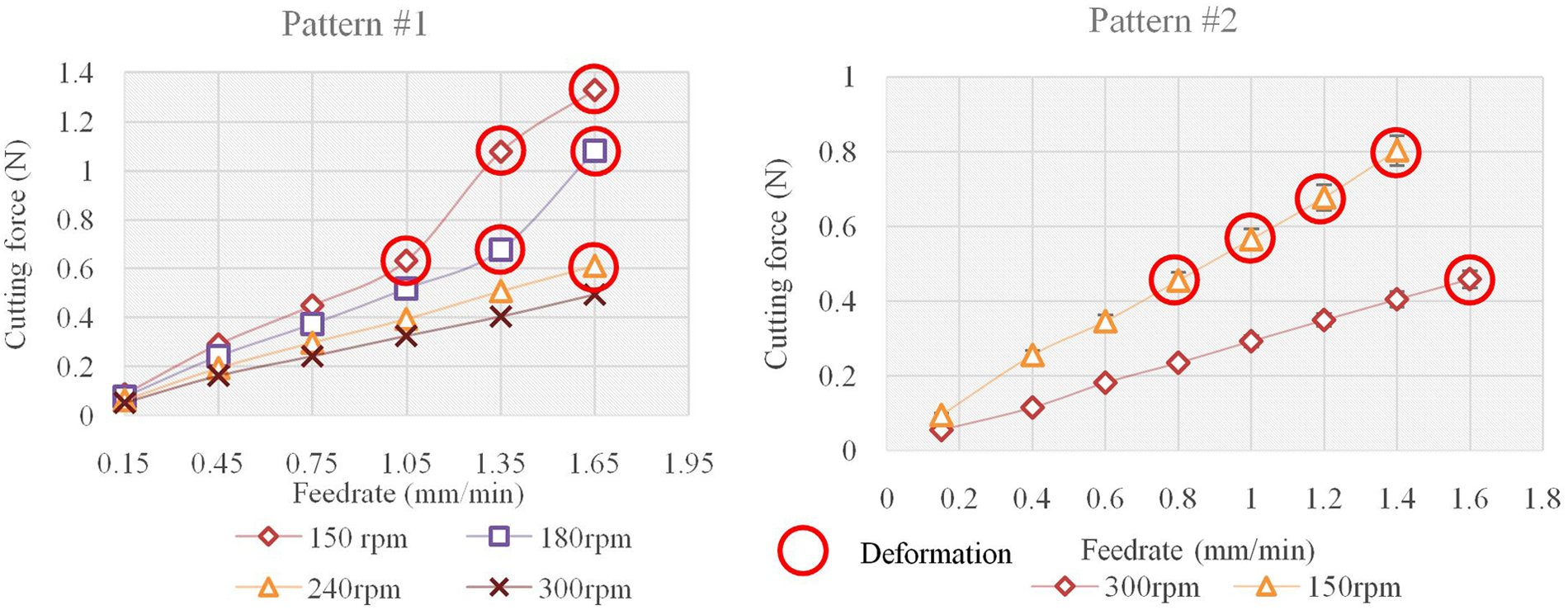
Measured cutting force versus feed rate.

(a) Top view of patterns, (b) blue inverse silicon replica of patterns, and (c) side view of silicon replica.
The relationship between cutting force and depth of cut per revolution is shown in Figure 14. The cutting conditions that had the same depth of cut per revolution also resulted in a similar cutting force. As the depth of cut per revolution increased, cutting force increased. When it exceeded a certain value, deformation occurred; as shown in Figure 14, the criteria limits were from 6 to 6.4 µm/r for pattern no. 1 and from 4.9 to 5.1 µm/r for pattern no. 2.
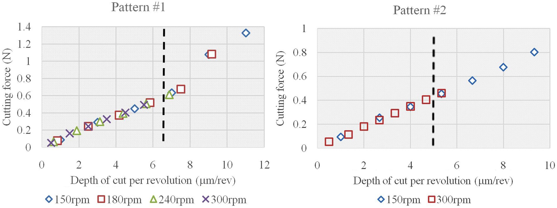
Cutting force versus depth of cut per revolution.
Based on the theoretical model described earlier, a MATLAB program was built to predict the cutting force and optimum cutting conditions. Relationships between predicted cutting force and feed rate are shown in Figure 15. The predicted cutting force showed good agreement with the measured cutting force. The predicted cutting force increased when feed rate increased; it also decreased when spindle speed increased. Both increase of the cutting force and feed rate for the two patterns showed good correlation between predictions and experimental measurements. Only two exceptions were observed for the 150 r/min case of pattern no. 1. When feed rate was higher than 1.2 mm/min, the measured cutting was higher than predicted cutting force’s. For these two cases, errors became significantly large. There are two possible explanations for this difference. First, the measurement may have been incorrect because of the unstable cutting conditions that occurred after the plate deformation. The other interpretation is shown in Figure 16. In normal cutting conditions, cutting tool makes three cutting force components, Fc, Ft, and Fr, on the workpiece. In reverse, cutting tool is under three reaction forces, the third of Newton’s laws of motion,
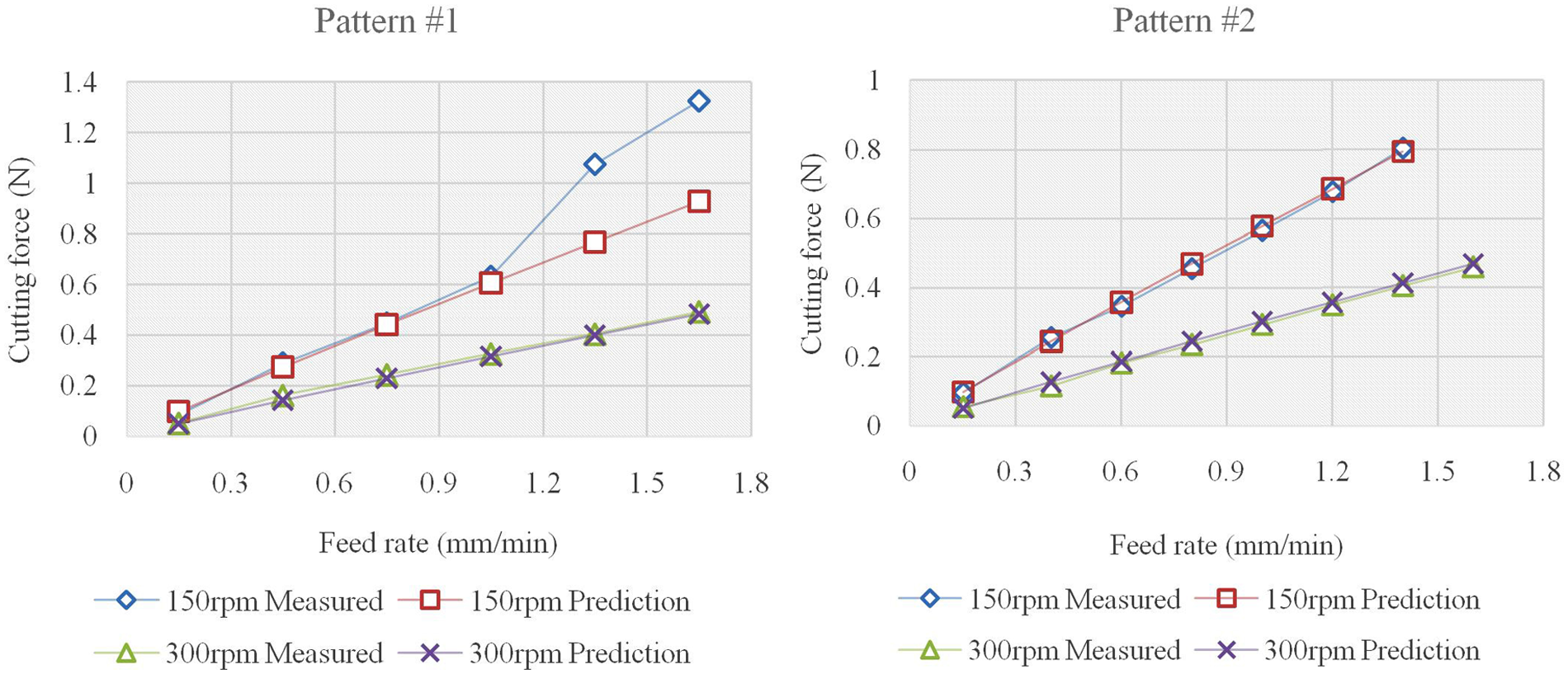
Predicted cutting force, measured cutting force, and feed rate.
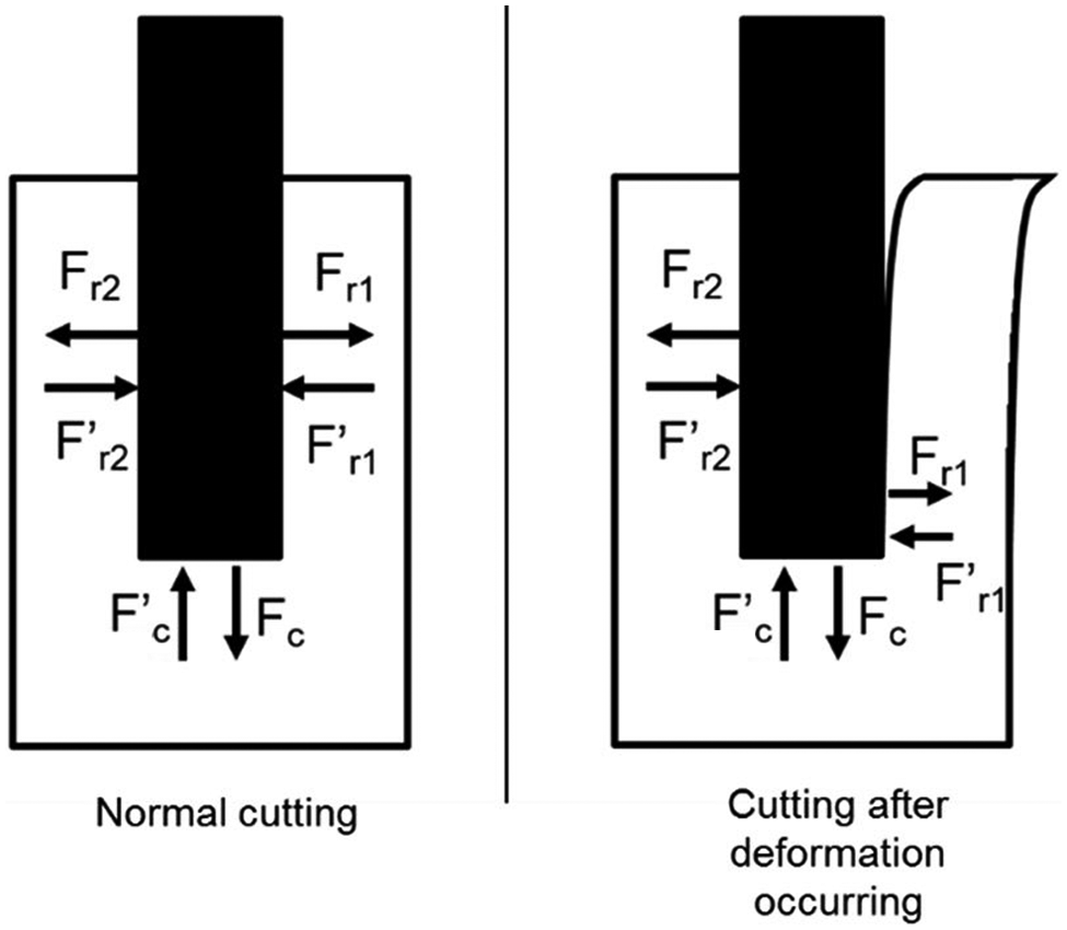
The unbalance of force components.
Figure 17 shows percentage errors between the measured cutting force and the predicted cutting force. The above described errors due to plate deformation were neglected, and the maximum error considered was 13.5% for all nondeformed cases. The average of these errors was 4.04%. These results verified that the cutting force prediction model for rectangular patterns worked well for nondeformation cases.
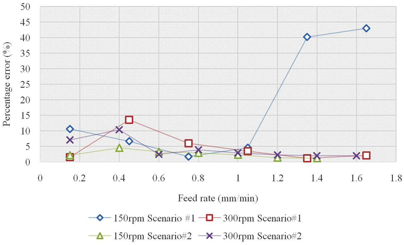
Percentage error in cutting force prediction.
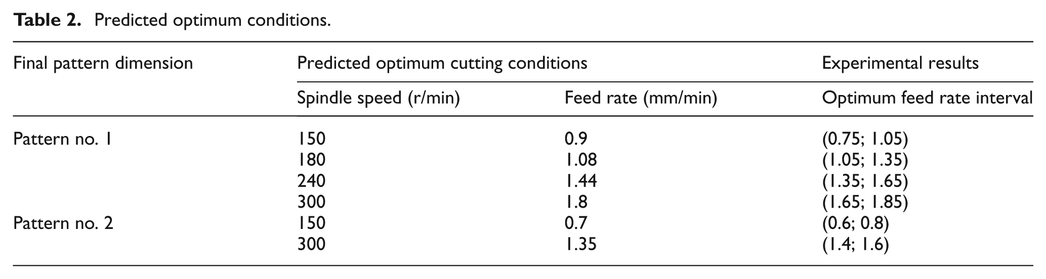
By applying the proposed method that recommends optimum cutting conditions for given patterns and the yield strength of workpiece material, the MATLAB program predicted the maximum feed rates for specific spindle speeds, as shown in Table 2. From the results of the experiments, optimum feed rate intervals were obtained. Table 2 shows that the predictions were almost all correct: five of the six predictions lie within the experimental optimum feed rate intervals. In the case of 300 r/min for pattern no. 2, the predicted value was slightly smaller than the actual value, but it is an acceptable value for manufacturing. Thus, it was verified that the cutting conditions recommended by the proposed models are useful.
Predicted optimum conditions.
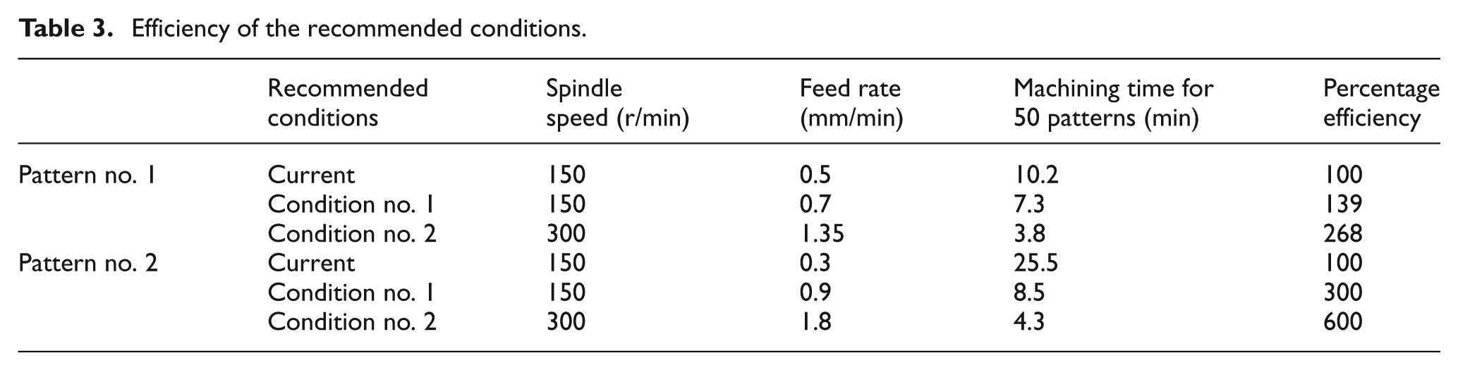
To clarify the efficiency of these predicted optimum conditions, cutting time was compared. We used values of 150 r/min and 0.5 mm/min for pattern no. 1 and 150 r/min and 0.3 mm/min for pattern no. 2. The machining times for 50 patterns for each pattern shape were measured. Figure 18 shows the difference between these machining times. For both pattern shape cases, the optimum cutting conditions recommended by the MATLAB program show a clear advantage in terms of machining time, as shown in Table 3. The highest efficiencies obtained were 268% for pattern no. 1 and 600% for pattern no. 2.
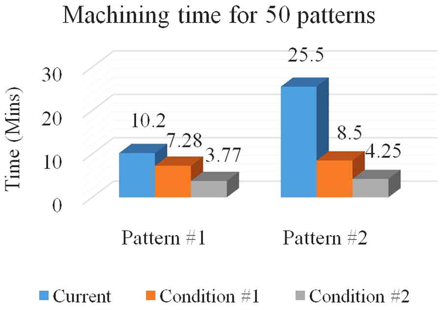
Machining times with specific cutting conditions (min).
Efficiency of the recommended conditions.
Conclusion
In this article, we have proposed a theoretical model for predicting the optimum cutting conditions for rectangular micropattern machining. Relationships between cutting conditions, cutting force, and deformation were studied by means of theory and experiments. We used diamond ultraprecision turning to perform several experiments to compare the results with the theoretical model. The main results are summarized as follows:
When spindle speed increases, cutting force decreases. When feed rate increases, cutting force increases. For given cutting conditions, the feed rate influences the machining time the most.
Depth of cut per revolution is one of the main factors in the deformation of rectangular pattern machining. When the depth of cut per revolution increases, cutting force increases and the deformation occurring increases as well.
In nondeformation case, the predicted cutting forces are in good agreement with the measured one. The maximum error was 13.5% for all nondeformation cases. The average of these errors was 4.04%.
The optimum cutting conditions given by the theoretical model agreed with the experimental results. Five of the six predictions lay within the experiment optimum feed rate intervals, and for the one remaining prediction, predicted cutting condition values were slightly smaller than the obtained experimental values but are acceptable in manufacturing. The machining time also shows clearly the advantage of these recommended cutting conditions.
The results of this study indicate that the proposal theoretical model works well. Further investigations on the influences of tool wear and chatter may help to improve the prediction accuracy. Future research investigating the application of this theoretical model for other pattern shapes such as trapezoids or triangles will need to be determined.
Footnotes
Appendix 1
Declaration of conflicting interests
The authors declare that there is no conflict of interest.
Funding
This research was supported by Basic Science Research Program through the National Research Foundation of Korea (NRF) funded by the Ministry of Education, Science and Technology (2012R1A1B4001609) and Industrial Core Technology Development Program funded by the Ministry of Knowledge Economy (10030831).